Enhancing Cellular Performance through Device-to-Device Distributed MIMO††thanks:
Abstract
The integration of local device-to-device (D2D) communications and cellular connections has been intensively studied to satisfy co-existing D2D and cellular communication demand. In future cellular networks, there will be numerous standby users possessing D2D communication capabilities in close proximity to each other. Considering that these standby users do not necessarily request D2D communications all the time, in this paper we propose a hybrid D2D-cellular scheme to make use of these standby users and to improve the rate performance for cellular users. More specifically, through D2D links, a virtual antenna array can be formed by sharing antennas across different terminals to realize the diversity gain of MIMO channels. This paper considers the use of millimeter wave (mmWave) links to enable high data rate D2D communications. We then design an orthogonal D2D multiple access protocol and formulate the optimization problem of joint cellular and D2D resource allocation for downlink transmissions using the proposed scheme. We obtain a closed-form solution for D2D resource allocation, which reveals useful insights for practical system design. Numerical results from extensive system-level simulations demonstrate that the rate performance of cellular users is significantly improved.
Index Terms:
Cooperative communications, MIMO, device-to-device communications, resource allocation.I Introduction
The fifth generation (5G) wireless networks are expected to meet the booming data traffic demand and to provide a better quality of service and user experience. The integration of device-to-device (D2D) communications into a traditional cellular network has been proposed as one of the promising technologies for 5G networks [1, 2]. D2D communications in cellular networks are mainly considered for local traffic handling, which enables direct communications between two mobile users without traversing the Base Station (BS) or core network. Studies have shown that this hybrid network can significantly increase network spectral efficiency (SE) and energy efficiency (EE) and alleviate the core network congestion[3].
However, we note that most current works are dedicated to increasing the SE and EE from the resource utilization point of view, instead of improving the cellular user performance. A typical scenario under the current D2D-cellular framework is that two user terminals communicate with each other directly through D2D links. But this is not the only scenario where D2D communication is useful. In this paper, we make an observation that with a large number of end-users in the network, there are numerous devices possessing D2D communication capabilities, but do not have a need of performing communications at any given time. We refer to the users who do not request cellular connections or D2D communications as standby users. Our idea here is to make use of the D2D capability of these standby users to improve the active cellular user performance. Since we only use standby users without D2D communication demand, our proposal can be applied on top of current D2D framework in a dense cellular network.
I-A Related Works and Motivation
I-A1 D2D communications
D2D communications in cellular networks can take place in the cellular spectrum (i.e., inband) or unlicensed spectrum (i.e., outband). The majority of current literature proposes to use the cellular spectrum for both D2D and cellular communications (i.e., underlay inband D2D). The arising co-channel interference between cellular users and D2D users is a major issue. Sophisticated resource allocation methods can be used to alleviate interference and to improve SE and EE, but most of them have high complexity [5, 4, 6]. The orthogonalization of D2D and cellular communications over the cellular spectrum (i.e., overlay inband D2D) can completely avoid such interference [7][8], but at the expense of a lower SE improvement as compared to underlay proposals.
Outband D2D genuinely enjoys interference-free transmissions for cellular and D2D users, which largely simplifies the user management at the BS [9]. However, it has been widely accepted that the traditional D2D technologies are inadequate. First, the widely known D2D technologies, such as Bluetooth and WiFi, work at the 2.4GHz unlicensed band. This band is rather crowded and thus the interference is uncontrollable. In addition, both Bluetooth and WiFi require manual pairing between two devices, which causes inconvenience in customer experience [10].
A promising technology of the future 5G networks is millimeter wave (mmWave) communication, providing multi-gigabits-per-second to the end users [11], making them potentially applicable to D2D communications. More importantly, the interference problem would be largely alleviated due to the highly directional antennas and large propagation loss in mmWave communications. In several proposed mmWave D2D communications, the pairing of D2D devices can be handled by BSs thus providing better user experience. For these reasons, this paper proposes to use mmWave D2D communications to complement current microwave cellular networks.
I-A2 Cooperative communications
Cooperative communications have been intensively studied in literatures and have been regarded as a focal technology in the cellular networks today [12][13]. In general, D2D communications can be utilized for cooperative communications, e.g., packet forwarding and relaying, and their impact is expected to be remarkable [14]. A major application of D2D relaying in cellular networks is multi-hop, which has been recognized to be capable of reducing transmission power and increasing network capacity. For example, when the D2D pairs are far away from each other, the direct link between the users is not good enough for communication and other devices can then relay signals between the D2D pairs [15]. In [16][17], multihop has also been proposed to enhance the cellular transmissions, where the user with a strong channel can forward the received message from the BS to a weak user via D2D links. This kind of relaying introduces so-called “hop gain”, which can be seen as a power gain.
Another way of relaying is to exploit the diversity gain through the distributed multiple-input and multiple-output (MIMO) technology. In [18], the concept of a virtual antenna array was proposed, where mobile users are clustered to form a virtual antenna array which emulates a MIMO device via D2D communications. A similar concept called “distributed antenna systems” has also gained attentions and has been shown to be able to cover the dead spots in wireless networks, extend service coverage, improve spectral efficiency and mitigate interference [19][20]. Specifically, such a system architecture can realize the potential diversity gain by sharing antennas across the different terminals to form a virtual MIMO system [21]. The authors of [9] proposed a shared user equipment-side distributed antenna system, which utilizes mmWave D2D links to enable a spatial multiplexing gain for single-antenna end users to improve the energy efficiency of outdoor-to-indoor communications. [22] studied cooperations between active cellular devices, and thus focused on how to pair these devices such that the average throughput is maximized. Yet, studies on this direction remains limited.
Most current studies tend to treat the D2D links as ideal high-rate connections and focus on the allocation of cellular resources [9][18]. We note that D2D connections are over wireless medium and D2D channel conditions may widely vary from one link to another due to fading and path loss, resulting in different D2D link capacities. In addition, different standby users may make different contributions to the rate of the destination users due to independent cellular channel realizations. Based on the above considerations, the following questions arise: i) which standby users should be enabled, and ii) how many D2D resources should be allocated to different standby users. These questions have been dealt with in [8]. However, their proposed algorithm is based on a multi-hop D2D-cellular scheme.
For a MIMO relay scheme, the joint optimization of the MIMO transmission and relaying strategies is a difficult task, because the information theoretical capacity of the relay channel is still an open problem [23]. The authors of [24] consider the scenario of a single cellular user with a single multi-antenna relay and then address the problem of jointly optimizing the transmit covariance and quantization noise covariance matrix. Their results confirm that optimized relaying can lead to significant throughput improvement. In order to simplify cooperative transmissions and reduce complexity at each relay (standby user), our scheme performs independent individual quantization at multiple single-antenna relays, which is different from the joint quantization at a single multi-antenna relay in [24]. Besides, individual relay-destination capacity constraints are considered instead of a sum relay-destination capacity constraint. In addition, we use the sum rate of multi-cell cellular users as our performance merit instead of a single user rate. These considerations impose new challenges in the joint optimizing MIMO transmission and relaying.
I-A3 Cellular networks
Classic communication theory has revealed great benefits of equipping multiple antennas on users in wireless channels [25, 26, 27]. Especially, the multiple antennas are able to enhance the capability of encountering inter-cell interferences, which accounts for the main cause of rate degradation in dense cellular networks. However, with the size limit of user equipment, it is difficult to equip the end users with many antennas in the current micro-wave cellular system and for this reason, comparative studies on the benefit of user side MIMO are limited. For example, in a multi-cell interfering broadcast channel, with multiple antennas at end-users, how many users should be scheduled as a function of transmit antennas at BS? How much performance gain can be obtained in practical systems? These questions have not yet been answered to the best of our knowledge. With the virtual antenna array formed via D2D links, multiple antennas at end-users in micro-wave cellular system become a real possibility. This paper examines these questions and quantifies the benefits of the proposed scheme through system-level simulations.
I-B Our Contributions
While the majority of current D2D-cellular works focus on the co-existing of D2D and cellular communications demand, this paper instead aims to employ D2D communications to improve the data rate and enhance the user experience of cellular users. Toward this end, this paper focuses on the multi-cell interfering broadcast channel. We summarize our contributions as follows.
-
•
We propose a hybrid D2D-cellular scheme applying the distributed MIMO technology to assist the cellular communications in 5G networks. With a user-clustering strategy, the active cellular user and its nearby standby users form a cluster. A MIMO channel is then emulated through D2D links from the BS to the cluster, providing a diversity gain for single-antenna end users. This is different from the existing multi-hop approach, which essentially provides a power gain. The virtual MIMO channel enhances the capability of inter-cell interference mitigation at end users, and thus improves the rate performance, especially for cell-edge users.
-
•
We employ mmWave communications for D2D links to avoid interference from cellular transmissions. We then propose an orthogonal D2D multiple access protocol to manage D2D interferences. The proposed protocol consists of time-division multiple access (TDMA) within one cluster and frequency division multiple access (FDMA) among different clusters, making use of the ample bandwidth provided by the mmWave communications.
-
•
We formulate a joint optimization problem of maximizing the sum rate over cellular transmit beamformers, cluster receive beamformers and D2D resource allocations for downlink transmissions of our proposed scheme. We obtain a closed-form solution for the D2D resource allocation problem, thereby quantitatively revealing the impacts of cellular signal strength and D2D link quality at each standby user for practical system design.
-
•
Extensive system-level simulations are performed to demonstrate the effectiveness of the proposed scheme. Compared with non-cooperation from standby users and the existing multi-hop method, approximately 2.5x to 2x improvement in terms of the 10th percentile user rate are observed when each cellular user is helped by 9 standby users. The comparison with equal resource allocation and our proposed algorithm confirms the necessity and advantages of optimizing the D2D resource allocation in our proposed scheme. In addition, we observe that fully loading the BSs is always the optimal strategy when the number of standby users exceeds a certain threshold, which is a useful insight for system design.
I-C Paper Organization and Notations
The paper is organized as follows. In Section II, we introduce the system model, present our proposed hybrid D2D-cellular scheme and formulate the utility maximization problem. For the formulated problem, we propose a two-step optimization algorithm in Section III. Section IV provides numerical results of a system-level simulation and discussions of insight.
Throughout this paper, column vectors (matrices) are denoted by boldface lower (upper) case letters. represents the transpose of a vector (matrix), represents the conjugate transpose, represents the pseudo inverse and represents the trace. denotes the complex number set and denotes a complex Gaussian distribution with zero mean and a variance .
II System Model and Proposed Hybrid D2D-Cellular Scheme
Consider a downlink multi-cell interfering broadcast channel with base stations (BSs) serving active users in each cell. Each BS , , is equipped with transmit antennas and each user, no matter active or non-active, has a single receive antenna. For the considered system model, it is widely recognized that inter-cell interference is the main cause of the rate degradation, especially in a dense cellular networks or for cell-edge users. In this paper, we propose a novel outband D2D cellular scheme, to enhance the capability of encountering the inter-cell interference for end-users.
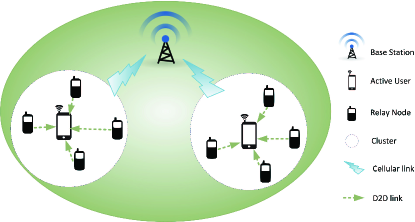
As illustrated in Fig. 1, our proposed scheme consists of a two-phase cooperative transmission procedure. In the first phase, the BSs transmits data to active users and standby users receive signals by “overhearing”. In the second phase, standby users help relay the received data to the active users so that multiple observations of the transmitted signals are jointly processed at the active users. The application of the distributed-MIMO technique here enhances the capability of inter-cell interference mitigation of end users, and thus improves the rate performance, especially for the cell-edge users.
In general, when designing a D2D communication scheme, peer discovery, physical layer procedures and radio resource management algorithms are the three main issues to be considered [28]. We note that the peer discovery required in our scheme is in line with conventional D2D communication schemes. We do not focus on this problem in the paper since existing peer discovery methods in literatures can be adopted. Instead, we focus on physical layer procedures in this section, and then radio resource management algorithms in Section III.
II-A Pre-Transmission: Clustering
In each BS, there are three type of users: active cellular users, users requesting D2D connections and standby users who do not request cellular nor D2D connections. Note that the number of these standby users is usually much larger than the number of active users. We propose a clustering strategy to make use of these standby users to enhance the rate performance of active users as follows.
We first define a maximum D2D communication range , which is the maximum geographical distance between two users allowed by the user power budget and the employed D2D communication technique. We then present some definitions for our proposed scheme as follows.
-
•
Relay node: For each active user in each cell, all its nearby standby users within the distance are its potential relay nodes. Among these nodes, those who are willing to help the active users111Users incentive for helping others has been studied in many literatures and is not the focus of this paper. are referred to as relay nodes. We assume that one relay node only helps one active user at the same time. We also assume that each BS is aware of the relay decisions of all relay nodes within its cell.
-
•
Cluster: After relaying decisions at potential relay nodes, an active user and its relay nodes thereby form a cluster. We assume that each active user has the same number of relay nodes for simplicity. We see that there are clusters of identical size within each cell. We assume that there are relay nodes for each active user, so that together with the direct link from the BS to each user, an MIMO channel can be formed for each active user.
Note that this clustering strategy limits the required transmission range of D2D links, which avoids the disadvantage of large propagation loss for long distance transmissions when operating at the mmWave carrier frequency. We assume that cellular devices in this paper are equipped with two wireless interfaces: LTE and mmWave, so that these users have both cellular and D2D communication capabilities. This is a realistic assumption based on the development trend of RF hardware [29].
II-B Phase I: BS-to-user transmission
In our proposed scheme, for each user, there is one direct link from the BS to the active user, and one-hop relay links. We denote the th active user in the cell of BS , , by user in this paper. We also assume that each active user has only a single data stream for simplicity. Then, let denote the beamformer that BS uses to transmit signals to user , and the transmitted signal from BS can be written as
| (1) |
where is the message for user and . We assume that is chosen from a Gaussian codebook and messages for different users are independent from each other and from receiver noises. Collecting all beamformers used by BS , we obtain the beamformer matrix . Then, the power budget of each BS can be presented as
| (2) |
The received signal at user can be written as
| (3) |
where , , represents the channel state information (CSI) vector from BS to user , and is the received noise at user and follows .
Due to the broadcasting property of the wireless channel, the relay nodes also receive the transmitted signals from BS by “overhearing”. The received signals at the th relay node of user , can be described as
| (4) |
where is the channel coefficient from BS to the th relay node of user and is the additive white Gaussian noise at the th relay node of user . We consider the same level of thermal noise at different users for simplicity.
II-C Phase II: Intra-cluster user cooperation
D2D communications between users within a cluster are enabled in Phase II to realize user cooperations and ultimately facilitate BS-to-user transmissions. We assume that D2D communications take place at E-band to obtain a large available bandwidth.
II-C1 Operations at each relay node
In this phase, relay nodes relay the received signals from Phase I to its helped active users. The relaying strategy at each relay node is chosen as follows. We note that our proposed scheme can be regarded as a general Gaussian relay channel, in which the channel of first hop (BS-to-relay) is weak (low signal-to-noise ratio) and the channel of second hop (relay-to-user) is relatively strong (high signal-to-noise ratio). Information theoretic considerations reveal that the compress-and-forward strategy is appropriate for such a relay channel [30]. Therefore, each observation at the th relay node of user , , is compressed and then forwarded to their active users.
We assume that the compression at each relay node is performed independently to simplify the intra-cluster cooperation. The compression procedure is modeled as the following forward test channel
| (5) |
where represents the compressed signal and is the quantization noise independent of . The quantization noise is also assumed to be Gaussian distributed with zero mean and variance . After performing this compression at relay node , the corresponding information rate of is
| (6) |
where
| (7) |
We can regard as a parameter representing the contribution of th relay node to user ’s achievable rate, which is defined later in (19). Smaller leads to a lower information rate of the compressed signal , while smaller quantization noise leads to a higher compression rate.
Now let us denote by the frame duration of cellular transmissions and by the cellular bandwidth. Then, during one frame duration, the required number of information bits to be transmitted from the th relay node to user is .
II-C2 Multiple access protocol
We now consider the multiple access aspect of multiple relay nodes transmitting to their targeted cellular user. We note that for mmWave communications in a dense network, the angles of arrive (AOAs) of signals from different relay nodes to one destination user might be rather close, and these signals would interfere with each other if they are transmitted simultaneously. Such interference can happen within one cluster as well as between different clusters. For example, relay nodes may interfere an unspecified cellular user when their AOAs are close to the AOAs of the intended signals at this cellular user.
Thus, the interference between simultaneous D2D transmissions must be managed. One possible solution here is to consider non-orthogonal multiple access (NOMA) from relay nodes to the destination user. However, the corresponding power allocation algorithm would be very complicated due to the large number of relay nodes. In addition, it has been widely recognized that successive interference cancellation (SIC) is required at the receiver for realizing NOMA, which would increase the implementation complexity at end-users. Furthermore, the error propagation issue of SIC is usually difficult to deal with [31]. For this reason, this paper adopts orthogonal multiple access to avoid interference and to simplify the operations at end-users.
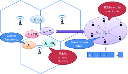
We propose orthogonal D2D transmissions as follows. As depicted in Fig. 2, we adopt FDMA among different clusters and TDMA within one cluster.
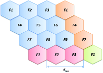
Among different clusters, we assume that the same bandwidth of is allocated to each cluster. Thus, a bandwidth of is required for serving all active users within one cell. To deal with D2D interference from adjacent cells, a multi-cell frequency reuse model is used as depicted in Fig. 3.222Denote the minimum distance between the sectors using the same frequency by . Using a common path loss model in [32, 33] and a power budget dBm, we calculate that as long as is larger than 940 m, the D2D inter-cell interference is less than 5% of noise power (noise power spectral density dBm/Hz). From Fig. 3, we see that larger than 940 m corresponds to a cell radius no less than 235 m. This fits the current network setups. Therefore, with this frequency reuse pattern, the inter-cell interference is negligible in determining the rate performance. With this frequency reuse pattern, the total required bandwidth is . This design makes use of the ample bandwidth exhibited by the mmWave communications. For example, at the E-band carrier frequency, a total of GHz is available. We may allocate a typical MHz bandwidth for each user allowing around FDMA clusters, which is capable of accommodating active cellular users within each cell.
Since FDMA is employed, all clusters are allowed to transmit simultaneously. Let us assume that the same time duration is available for each cluster in Phase II. Within each cluster, each relay node is allocated with an exclusive transmission duration, which is the D2D resource allocation parameter to be optimized. In this manner, interferences between D2D links are thoroughly avoided.
Denote by the allocated time duration to the D2D link from relay node to user . The D2D link constraint can then be described as
| (8) |
Assuming a power budget for D2D transmissions at each relay node, we further obtain that the actual channel capacity allowed by the D2D channel is
| (9) |
where represents the channel coefficient of the D2D link from relay node to user , and is noise power spectral density. Thus, we see that a total number of information bits can be transmitted via the D2D link from relay node to user .
Therefore, to guarantee no information loss through the D2D transmissions, for the th relay node of user , the number of transmitted information bits via the D2D link must be larger than or equal to the required number of compression bits . That is to say, the condition must be satisfied for any . In other words, we see that the allocated time duration for the th relay node of user must satisfy
| (10) |
The ratio can be regarded as a constant determined by system parameters. We see that larger the required compression information rate and smaller the actual channel capacity , more D2D time resource is required for relay node .
Remark 1
Phase I and Phase II must happen consecutively without overlapping. This is because in our design, one relay node is required to deliver information to the active user in Phase II, after collecting all the received signals from Phase I.
II-D Equivalent transmission model
As illustrated in Fig. 4, for active user , upon collecting all the compressed observations from its relay nodes in Phase II and its direct observation , the received signals at user can be arranged as
| (11) |
The equivalent transmission model from BS to user can be further written as
| (12) |
where
| (14) | |||||
| (16) |
and
| (18) |
We see that is a collection of i.i.d. Gaussian random variables and . The vector collects independent quantization noises from relay nodes, whose last element is zero since there is no quantization noise in the direct BS-to-user transmission.
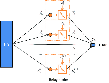
Thus, by jointly processing the compressed observations and the direct observation , user and its relay nodes realize a distributed-MIMO channel. Then, the achievable rate for user is written as
| (19) |
where
| (22) |
and
| (23) |
Considering the fact that Phase I and Phase II happen consecutively, the actual information rate of user is
| (24) |
We see that by permitting adjacent users to cooperate with each other, users located in different locations can form a virtual antenna array. This allows the deployment of MIMO techniques to single-antenna users and enhances the channel capacity by diversity gain.
We further notice that with multiple observations at each user, receive beamforming is also required for our proposed scheme to better realize the MIMO capacity. In this paper, we treat interference as noise and consider a linear receive beamforming strategy. So the estimated message is given by
| (25) |
where is the receive beamformer at user . We see that the receive beamformer is also a parameter to be optimized.
II-E Problem Formulation
Under the context of the multi-cell interfering broadcast channel, a popular utility maximization problem is to find the optimal transmit and receive beamformers, so that the sum rate is maximized. On top of this, we note that the resource allocation for D2D links is also important for our proposed scheme. This is because from (6) and (10) we see that the quantization noise variance matrix is constrained by the allocated time duration of D2D links, which ultimately affects the user rate . This section formulates a problem of multicell sum rate maximization by jointly optimizing transmit beamformers, receive beamformers and quantization noise variance matrices. We also note that the CSI knowledge in this paper includes the CSI from BSs to active users as well as that from BSs to relay nodes.
Intuitively, there are two primary factors affecting the allocated time duration for each relay node: one is its rate contribution to cellular user rate , brought by the cellular observation at relay node , and the other is the D2D link quality from relay node to user . These two factors may vary at different relay nodes due to different cellular and D2D channel realizations. It is immediate to see that if a relay node has very weak cellular observations and poor D2D connections, we should avoid allocating much transmission time to it. And it is also obvious that a relay node with strong cellular observations and good D2D connections should be allocated with a fair amount of transmission time. However, these extreme situations are not common. For any given cellular and D2D channel realizations, how do we quantitatively allocate a reasonable transmission time for each relay node? This D2D resource allocation problem is important yet challenging since there is not a straightforward relationship between the individual cellular observation at each relay node, the D2D link quality and the rate of the destination user.
In this paper, the network utility maximization problem is formulated as follows:
| (31) |
where is defined as in (24), C1 is the information flow constraint that accounts for lossless information passing through D2D links, C2 is the transmission time constraint for D2D links and C3 is the BS transmission power constraint.
We see that C1 must be satisfied with equality, i.e.,
| (32) |
This is because the objective function monotonically decreases with , which also decreases with the capacity of the D2D link . To maximize , should be as large as possible.
To better understand the property of problem , we transform it into optimizing over the quantization noise covariance instead of the allocated time as follows. Denote
| (33) |
which can be interpreted as a parameter measuring the D2D link quality. Smaller the is, better the D2D link is. Thus, using this notation and together with (6), we combine C1 and C2, and obtain the new D2D link constraints as
| (34) |
Then, we obtain the following problem:
| (37) |
We see that is not a convex problem. The major difficulty in solving arises from the fact that the objective function and the constraints are both concave in transmit beamformer and convex in quantization noise covariance .
III Enhanced Rate-performance of Cellular Users
In this section, we propose a two-step iterative optimization method for the formulated problem . In the following, we show that for given beamformers and , the optimization of the quantization noise covariance can be transformed into a convex problem and solved in closed-form by applying the Karush-Kuhn-Tucker (KKT) conditions. Then, the optimization of beamformers and under fixed quantization noise covariance can be regarded as a general multi-cell sum rate maximization problem. A coordinate descent algorithm is used by applying an iterative optimization between the two steps, leading to an appropriate use of D2D links.
III-A Optimized D2D resource allocation
We first assume that all transmit and receive beamformers are fixed. Then, for given beamformers and , the problem of quantization noise covariance optimization at the relay node for each single-antenna user can be described as follows:
| (40) |
Problem is a non-convex problem and we transform it to a convex problem as follows. Note that is equivalent to minimizing the mean square error (MSE) since a single user rate is considered. Thus, instead of solving , we study the following problem:
| (43) |
where
| (46) | |||||
| (47) |
Then, by substituting (6) into (47), we have
| (50) |
We see that the above problem is a convex optimization problem, since the constraint is linear and the objective function is convex, which can be verified by taking the second derivative in . Now introducing Lagrange multiplier and , , , we form the Lagrangian
| (51) |
Taking the derivative of the above with respect to , we apply the KKT condition as follows:
| (52) |
Note that whenever . Now, the optimal must satisfy the D2D constraint C4 with equality, i.e.,
| (53) |
This is because the objective function in monotonically decreases with . Solving the condition (52), we obtain the following optimal as
| (54) |
where
| (55) |
and is chosen such that (53) is satisfied. Recall that represents the cellular rate contribution while indicates the D2D link quality. Then, the parameter here represents a quantitative and comprehensive description of the cellular observation strength and the D2D link quality of relay node .
The insights of the above solution are threefold.
-
1.
The ratio is the key parameter when allocating D2D resources. This water-filling like solution means that we should always allocate more time to relay nodes with strong cellular observations and good D2D link qualities.
-
2.
Based on definitions in (32) and (33), together with (54), we obtain the allocated time to the th relay of user as
(56) We notice that the cellular rate contribution parameter affects the allocated time duration through a log function. The saturation of log function at a large-value variable indicates that if the received signals at all relay nodes are strong ( large for all ), the D2D link quality is the main factor to be considered. A naive linear allocation based on D2D link quality would be sufficiently effective under this circumstance.
-
3.
When the D2D link qualities are roughly at the same level within one cluster, a relatively small means that the rate contribution from relay node to the destination is rather limited. In this case, we can remove relay node from the cluster. Thus, this solution can be used as a criterion of selecting relay nodes when determining user clusters.
III-B Joint optimization of Tx. beamformer and Rx. beamformer
With the optimized D2D allocation and corresponding quantization noise variances at relay nodes, we then consider the beamformer optimization for our proposed scheme as follows:
| (59) |
We note that such a sum rate maximization problem has been intensely addressed in many literatures. Especially, in the context of coordinated beamforming at different BSs, a weighted minimum mean square error (WMMSE) approach has been proposed to solve a similar problem [34] and shown great effectiveness though numerical experiments. However, this method has a high computation complexity when considering a large multi-cell model with multiple antennas at each user. Since our focus here is to study the benefits of user cooperations in the cellular network, we do not consider high-complexity algorithms for BS cooperations in this paper.
Instead, we assume a simple situation that each BS performs random scheduling and zero-forcing beamforming for the active users within its own cell. Under this assumption, the benefits of user cooperations through D2D links alone are examined and advanced BS cooperations can be further carried out on top of our proposed scheme.
Given the considered non-cooperative BSs, we adopt a random scheduling strategy at each BS as follows. In each cell, out of the active users are randomly scheduled and all users must have been scheduled once after frame durations333Note that is usually set to be an integer number for simplicity.. Denote by the set of scheduled users in the cell of BS at time , . Then, problem becomes
Then, the actual rate of user is
| (60) |
since each user is served every frame durations.
For each scheduled user , fixing all the transmit beamformers and minimizing the MSE, we obtain the well-known MMSE receiver:
| (61) |
Then, the equivalent channel from BS to user can be seen as . Collecting all for scheduled users of BS at time-slot , we have . Zero-forcing transmit beamforming can be easily applied using the pseudo inverse of [35], i.e.,
| (62) |
We then use the following algorithm for solving : First, find the optimal quantization noise covariance for given beamformers using the solution in Section III.A; Then, compute the optimal for given transmit beamformers and quantization noise covariances using (40), and update the transmit beamformer based on (41). Iterate above two steps until convergence. By doing so, we integrate two optimization problems and , and thus jointly optimize the cellular and D2D resource allocation. We use Algorithm 1 to further illustrate our proposed resource allocation algorithm. Note that a steady convergence of Algorithm 1 is observed in simulations.
IV Simulation Results
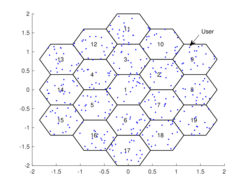
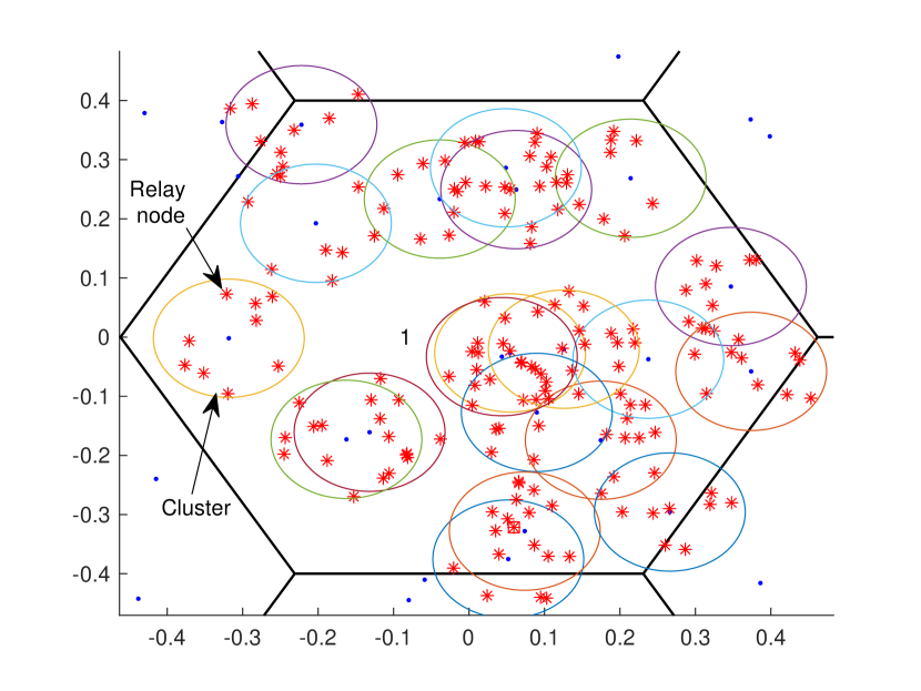
In this section, numerical simulations are conducted to show the effectiveness of the proposed algorithms. To fully demonstrate the inter-cell interference mitigation, we consider a 19-cell wrapped-around network with the simulation parameters listed in Table I. Each cell is a regular hexagon with a single BS located at the center, within which cellular users are randomly distributed as shown in Fig. 5(a). A circle centered at the each cellular user with a radius of illustrates the user clustering as shown in Fig. 5(b).
The cellular wireless channel is centered at a frequency of GHz and has a bandwidth MHz, following the 3GPP LTE-A standard. The mmWave wireless channel is centered at a frequency of GHz, and has several orthogonal sub-bands of MHz so that an exclusive bandwidth can be occupied by each cluster, which is shared within one cluster via TDMA. The channel from the relay nodes to each cellular user has line-of-sight (LoS), with the path loss given by dB[32]. In addition, we consider a Nakagami fading with the Nakagami parameter as assumed in many mmWave D2D works. Each relay node is assumed to transmit at a fixed power of dBm with an antenna gain of dBi [33].
| (39) |
and
| (40) |
We compare the performance of the following benchmark schemes with our proposed scheme by extensive system-level simulations.
Benchmark Scheme 1: No user cooperation. We assume that each single-antenna user has no relay node. This can be regarded as the performance baseline. If the rate performance of our proposed scheme is even worse than this benchmark, there is no need to perform user cooperation as proposed.
Benchmark Scheme 2: Ideal user cooperation. Consider an ideal case of infinite D2D link capacity, which is obtained by assuming no quantization noise at the relay nodes, i.e., fixing . This can be seen as a performance upper bound of our proposed scheme. In this case, since an infinite D2D link capacity is assumed, having relay nodes for each cellular user is equivalent to that each user is equipped with geographically dispersed receive antennas.
Benchmark Scheme 3: Equal D2D resource allocation. Consider an equal D2D resource allocation, where each relay node occupies the same length of transmission time, i.e.,
| (37) |
Benchmark Scheme 4: Multi-hop D2D cooperation. Consider a multi-hop D2D cooperation scheme as in past literature [16][17]. Within one cluster, the relay node with the strongest channel will decode the message from BS and forward it to the user through the D2D connection. We assume that the cellular and D2D transmissions happen consecutively with a negligible time delay caused by establishing the relay link. Also, the D2D link capacity is much larger than the cellular transmission rate. Thus, the achievable rate of user is the maximum rate within its cluster, i.e.,
| (38) |
| Cellular Layout | Hexagonal 19-cell wrapped-around |
|---|---|
| Cellular bandwidth | MHz |
| Cellular frame duration | ms |
| D2D bandwidth for one cluster | MHz |
| Distance between cells | km |
| Max. D2D transmission range | m |
| Num. of users | |
| Max. Tx power for BSs | dBm |
| Max. Tx power for Relay nodes | dBm [33] |
| Cellular Antenna gain | dBi |
| D2D Antenna gain(mmWave) | dBi [33] |
| Background noise | dBm/Hz |
| Path loss from BS to user | dB |
| Path loss of D2D link | dB[32] |
| Log-normal shadowing | dB |
| Rayleigh small scale fading | dB |
| Nakagami parameter of D2D links |
For the above benchmark schemes and our proposed scheme, Algorithm 1444If Benchmark Scheme 1 and 4 are considered, omit the step 1 within each iteration. is executed over different channel realizations to measure the cellular rate performance by the averaged long-term rate. We have for the shown results in this paper.
| Scheme | 10th Percentile Rate (Mbps) | Gain | 50th Percentile Rate (Mbps) | Gain |
|---|---|---|---|---|
| Benchmark 1 (No-user-cooperation) | 3.85 | N/A | 6.58 | N/A |
| Benchmark 3 (Ideal - 1 relay node) | 3.17 | -17.7% | 7.10 | 7.9% |
| Benchmark 3 (Ideal - 4 relay nodes) | 8.38 | 117.7% | 13.70 | 108.2% |
| Proposed (4 relay nodes) | 6.25 | 62.3% | 10.78 | 63.9% |
| Benchmark 3 (Ideal - 9 relay nodes) | 14.60 | 279.2% | 20.58 | 212.8% |
| Proposed (9 relay nodes) | 9.69 | 151.7% | 14.54 | 121.0% |
IV-A How much performance gain can be achieved considering multiple antennas at end-users?
In order to examine the potential of our proposed framework under practical system settings, we compare Benchmark Scheme 1 and Benchmark scheme 2 to check how much rate improvement can be achieved under infinite D2D link capacity.
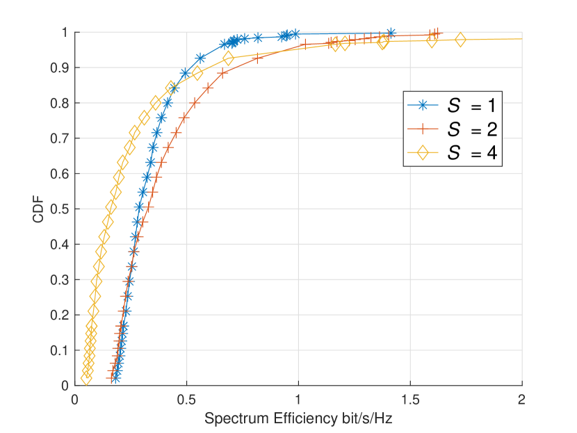
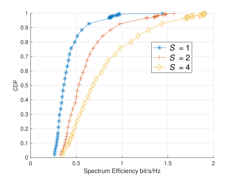
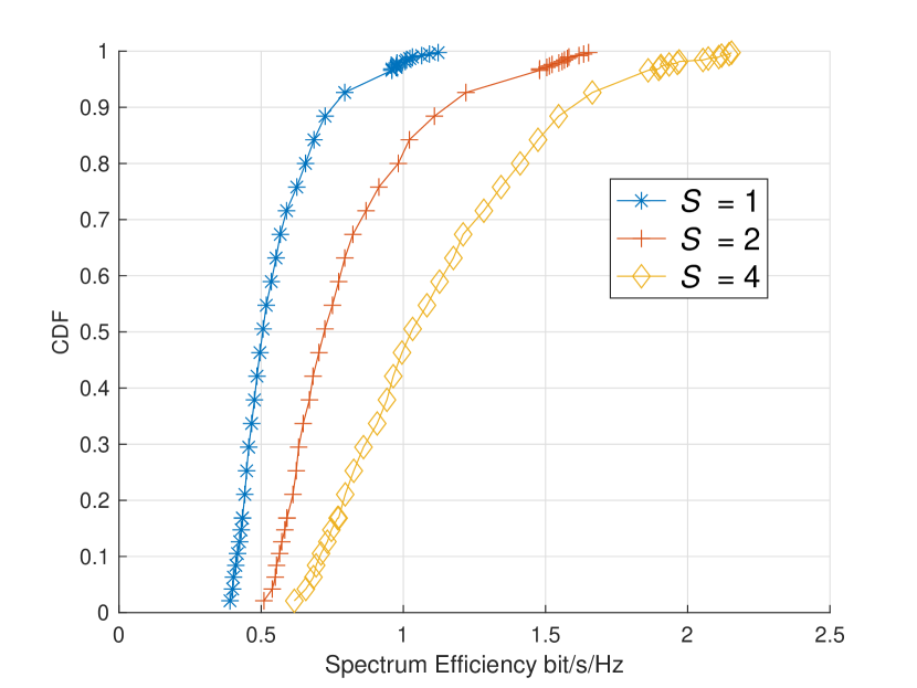
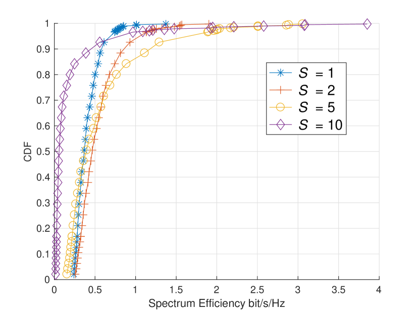
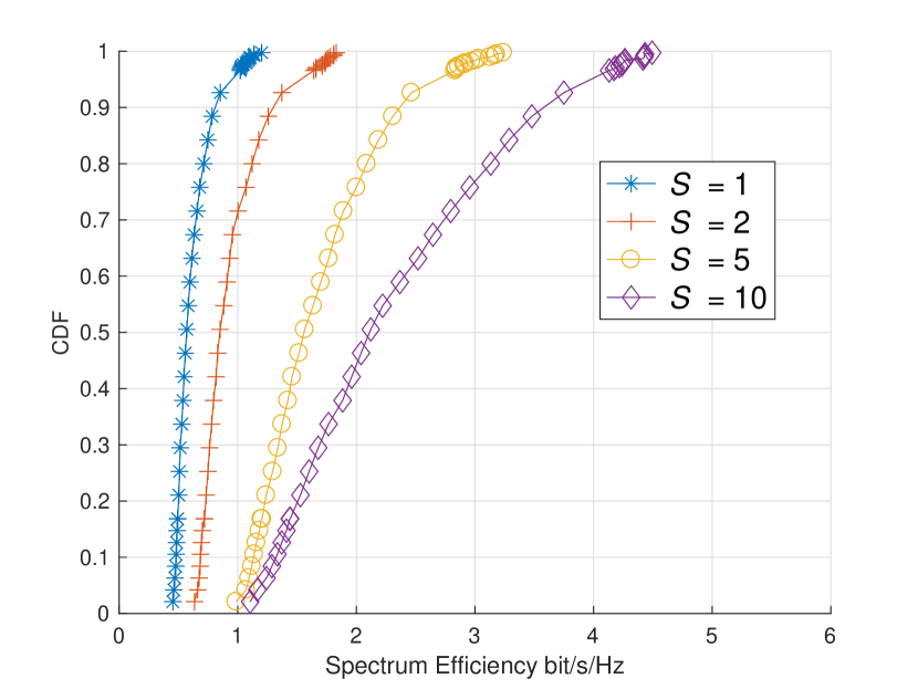
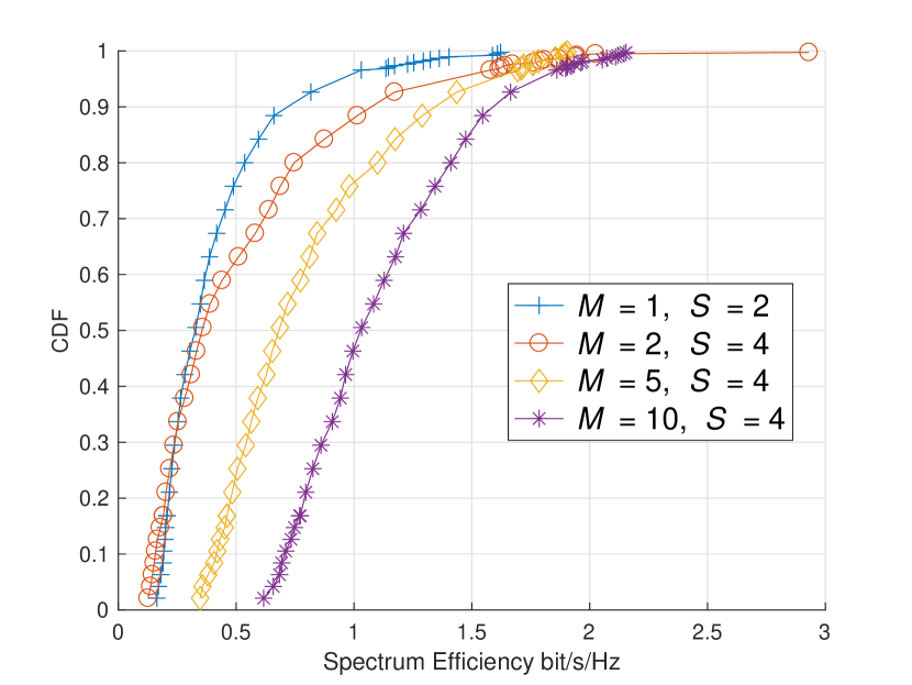
Before investigating the rate improvement by multiple antennas at end-users, we first have to examine the effects of the number of scheduled users on the rate performance, and eliminate the influence of user scheduling. Fig. 6 shows the cumulative distributions of the long-term average user rates, with various number of receive antennas and number of scheduled users when the number of transmit antennas . Fig. 7 shows the cumulative distributions with the same parameters except for . We notice that the case stands for the Benchmark Scheme 1 without user cooperations. Comparing Fig. 6(a) - Fig. 6(d), we observe that when the number of receive antennas is limited, the relationship of rate performance and the number of scheduled users is not straightforward. For example, as shown in Fig. 6(a), when and there is no relay node, scheduling 2 users at a time () achieves the best performance. While with one relay node at each user, Fig. 6(b) shows that the case of achieves the best performance.
However, it is interesting to note that when the number of receive antennas exceeds a certain threshold,555Note that is a reasonable setup under the 5G vision where one user per is expected. fully loading the BS, i.e., setting the number of scheduled users to be equal to the number of BS transmit antennas , is always the optimal strategy. For instance, we see that full loading achieves the best SE when in Fig. 6 and when in Fig. 7. This is a practical insight for designing user scheduling of future multiple antenna systems.
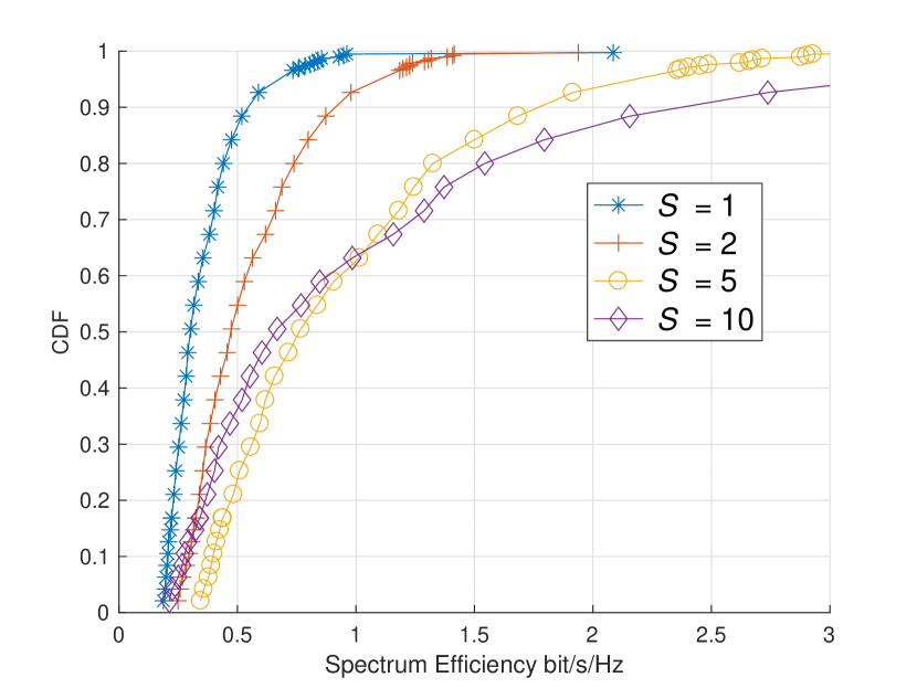
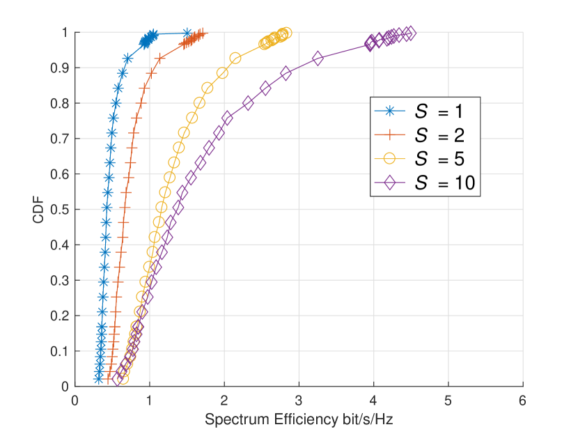
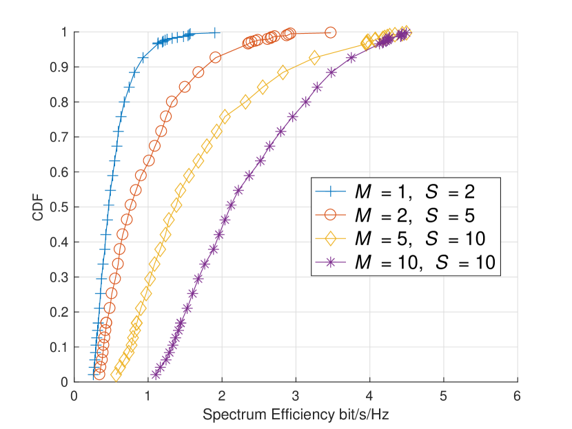
Next, we eliminate the influence of the user scheduling and focus on examining the benefits of user cooperations. That is, for given numbers of transmit and receive antennas , , we pick up the cases with the best rate performance and then compare their SE in Fig. 8(a) and Fig. 8(b), respectively. We see that both figures show great improvement in terms of rate performance of the cellular users as the number of receive antennas increases. For example, in Fig. 8(b), when , an improvement up to 4.5x is observed with for the 50th percentile users compared with the case of .
We list the rate improvement for the 10th and 50th percentile users when in Table II. A huge rate improvement is observed for both types of users and the rate improvement increases as the number of receive antennas increases. For instance, when , compared with the non-cooperative Benchmark Scheme 1, for the 10th percentile user, we obtain a 117.7% rate improvement when , while 279.2% more rate is achieved when . Due to the different user path loss, the rate improvement is not linear with the number of receive antennas as indicated by MIMO theory. However, the improvement brought by this D2D cellular framework is still significant and useful for encountering inter-cell interference. In addition, we also note that this improvement for low-rate users is especially meaningful since it largely enhances the performance of cell-edge users and thus improves user experience.
IV-B The effectiveness of our proposed resource allocation
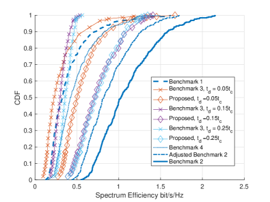
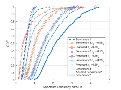
Next, we consider the physical limits of D2D links and examine the effectiveness of our proposed resource allocation algorithm. Fig. 9 and Fig. 10 compare the cumulative distributions of the long-term average user rates for the Benchmark Scheme 3 (equal allocation), the Benchmark Scheme 4 (multi-hop) and our proposed algorithm. We also show the curve of Benchmark 1 as a baseline and that of Benchmark 2 as an upper bound in the figures.
Both figures demonstrate an impressive enhancement brought by our proposed allocation algorithm. For example, if using the equal allocation strategy, the rate performance shows a rather limited improvement. What’s worse, as shown in Fig. 9, when the D2D transmission time ( is the cellular frame duration), the rate might be even degraded since the small rate increase brought by the D2D links cannot compensate the consumed time duration for D2D links. On the other hand, we can see that our optimized allocation guarantees an improvement of user rate under different D2D transmission time . We also observe that our proposed algorithm, which utilizes a diversity gain, largely outperforms the Benchmark Scheme 4 (multi-hop D2D cooperation) which achieves a power gain under various system setups.
We also list the improvement for the 10th and 50th percentile users when in Table II. Similarly, we see that a huge rate improvement is observed for both types of users and the rate improvement increases as the number of relay nodes increases. Especially, a 2.5x improvement in terms of the 10th percentile user rate is observed when each cellular user is helped by 9 standby users. It is interesting to observe that the optimized D2D allocation for and achieves almost the same rate performance. This can be interpreted as that the rate increase brought by better D2D connections from and is cancelled by the increasing consumed time duration on the D2D links.
We further notice that although there seems to be a big gap between the rate performance of our optimized allocation and that of Benchmark 2, our curve is already close to the ideal case where the D2D link capacity is assumed to be infinite. This is because the gap here mainly comes from the average over the total transmission time when calculating the rate, while in Benchmark 2 we have . If we also multiply the ratio to the rate of Benchmark 2 (shown as “Adjusted Benchmark 2” in Fig. 9 and Fig. 10), we can see that the rate of our proposed method approaches that of Benchmark 2.
We would like to point out that the CSI from the BS to relay nodes is essential in our scheme. This is because without the relay CSI, the transmit beamformer is still designed based on a single receive antenna model, thus the interference cannot be effectively managed. Numerical results also confirm this and we do not show here due to the length limit.
V Conclusion
The integration of local device-to-device (D2D) communications and cellular connections has been intensively studied to meet the co-existing requirement of D2D and cellular communications. In this paper, we exploited the D2D communication capability of standby users and proposed a hybrid D2D-cellular scheme applying the distributed MIMO technology to improve the data rate and user experience for cellular users. More specifically, a virtual antenna array was formed by sharing antennas across different terminals to realize the diversity gain of MIMO systems. To achieve this, mmWave D2D links were considered to enable high data rate D2D communications. We then designed a D2D multiple access protocol and formulated the optimization problem of joint cellular and D2D resource allocation for downlink transmissions of our proposed scheme. We obtained a closed-form solution for the D2D resource allocation, which revealed useful insights for D2D resource allocation. Extensive system-level simulations were performed to demonstrate the effectiveness of the proposed scheme.
References
- [1] K. Doppler, M. Rinne, C. Wijting, C. B. Ribeiro and K. Hugl, “Device-to-device communication as an underlay to LTE-advanced networks,” IEEE Communications Magazine, vol. 47, no. 12, pp. 42-49, Dec. 2009.
- [2] D. Feng, L. Lu, Y. Yuan-Wu, G. Y. Li, S. Li and G. Feng, “Device-to-device communications in cellular networks,” IEEE Communications Magazine, vol. 52, no. 4, pp. 49-55, April 2014.
- [3] X. Lin, J. G. Andrews, A. Ghosh and R. Ratasuk, “An overview of 3GPP device-to-device proximity services,” IEEE Communications Magazine, vol. 52, no. 4, pp. 40-48, April 2014.
- [4] D. Feng, L. Lu, Y. Yuan-Wu, G. Y. Li, G. Feng and S. Li, “Device-to-Device Communications Underlaying Cellular Networks,” IEEE Transactions on Communications, vol. 61, no. 8, pp. 3541-3551, August 2013.
- [5] C. Xu et al., “Efficiency Resource Allocation for Device-to-Device Underlay Communication Systems: A Reverse Iterative Combinatorial Auction Based Approach,” IEEE Journal on Selected Areas in Communications, vol. 31, no. 9, pp. 348-358, September 2013.
- [6] X. Lin, J. G. Andrews and A. Ghosh, “Spectrum Sharing for Device-to-Device Communication in Cellular Networks,”IEEE Transactions on Wireless Communications, vol. 13, no. 12, pp. 6727-6740, Dec. 2014.
- [7] Y. Pei and Y. C. Liang, “Resource Allocation for Device-to-Device Communications Overlaying Two-Way Cellular Networks,” IEEE Transactions on Wireless Communications, vol. 12, no. 7, pp. 3611-3621, July 2013.
- [8] B. Zhou, H. Hu, S. Q. Huang and H. H. Chen, “Intracluster Device-to-Device Relay Algorithm With Optimal Resource Utilization,” IEEE Transactions on Vehicular Technology, vol. 62, no. 5, pp. 2315-2326, Jun 2013.
- [9] D. W. K. Ng, et al., “Energy-Efficient 5G Outdoor-to-Indoor Communication: SUDAS Over Licensed and Unlicensed Spectrum,” IEEE Transactions on Wireless Communications, vol. 15, no. 5, pp. 3170-3186, May 2016.
- [10] H. Min, J. Lee, S. Park and D. Hong, “Capacity Enhancement Using an Interference Limited Area for Device-to-Device Uplink Underlaying Cellular Networks,” IEEE Transactions on Wireless Communications, vol. 10, no. 12, pp. 3995-4000, December 2011.
- [11] J. G. Andrews et al., “What Will 5G Be?,” IEEE Journal on Selected Areas in Communications, vol. 32, no. 6, pp. 1065-1082, June 2014.
- [12] C. Lin and M. Gerla, “Adaptive clustering for mobile wireless networks,” IEEE Journal on Selected Areas in Communications, vol. 15, no. 7, pp.1265–1275, 1997.
- [13] B. Dai and W. Yu, “Sparse Beamforming and User-Centric Clustering for Downlink Cloud Radio Access Network,” IEEE Access, vol. 2, pp. 1326-1339, 2014.
- [14] F. Fitzek, M. Katz and Q. Zhang, “Cellular Controlled Short-Range Communication for Cooperative P2P Networking,” Wireless Personal Communications, vol. 48, issue 1, pp 141–155, January 2009.
- [15] H. Nishiyama, M. Ito and N. Kato, “Relay-by-smartphone: realizing multihop device-to-device communications,” IEEE Communications Magazine, vol. 52, no. 4, pp. 56-65, April 2014.
- [16] Y. Cao, T. Jiang and C. Wang, “Cooperative device-to-device communications in cellular networks,” IEEE Wireless Communications, vol. 22, no. 3, pp. 124-129, June 2015.
- [17] F. Hou, L. X. Cai, P. H. Ho, X. Shen and J. Zhang, “A cooperative multicast scheduling scheme for multimedia services in IEEE 802.16 networks,” IEEE Transactions on Wireless Communications, vol. 8, no. 3, pp. 1508-1519, March 2009.
- [18] M. Dohler, “Virtual antenna arrays,” PhD thesis, University of London, 2004.
- [19] R. Heath, S. Peters, Y. Wang, and J. Zhang, “A current perspective on distributed antenna systems for the downlink of cellular systems,” IEEE Communications Magazine, vol. 51, no. 4, pp. 161–167, Apr. 2013.
- [20] H. Zhu, “On frequency reuse in cooperative distributed antenna systems,” IEEE Communications Magazine, vol. 50, no. 4, pp. 85–89, Apr. 2012.
- [21] J. Jiang, J. S. Thompson and H. Sun, “A Singular-Value-Based Adaptive Modulation and Cooperation Scheme for Virtual-MIMO Systems,” IEEE Transactions on Vehicular Technology, vol. 60, no. 6, pp. 2495-2504, July 2011.
- [22] S. H. Lee, D. R. Shin, H. W. Jeong and Y. H. Kim, “Distributed Bargaining Strategy for Downlink Virtual MIMO With Device-to-Device Communication,” IEEE Transactions on Communications, vol. 64, no. 4, pp. 1503-1516, April 2016.
- [23] G. Kramer, M. Gastpar and P. Gupta, “Cooperative Strategies and Capacity Theorems for Relay Networks,” IEEE Transactions on Information Theory, vol. 51, no. 9, pp. 3037-3063, Sept. 2005.
- [24] S. A. Ayoughi and W. Yu, “Optimized MIMO transmission and compression for interference mitigation with cooperative relay,” IEEE International Conference on Communications (ICC), pp. 4321-4326, 2015.
- [25] Q. H. Spencer, A. L. Swindlehurst and M. Haardt, “Zero-forcing methods for downlink spatial multiplexing in multiuser MIMO channels,” IEEE Transactions on Signal Processing, vol. 52, no. 2, pp. 461-471, Feb. 2004.
- [26] Y. Li and H. Kan, “Complex Orthogonal Designs With Forbidden 22 Submatrices,” IEEE Transactions on Information Theory, vol. 58, no. 7, pp. 4825-4836, July 2012.
- [27] X. Liu, Y. Li and H. Kan, “On the Minimum Decoding Delay of Balanced Complex Orthogonal Designs,” IEEE Transactions on Information Theory, vol. 61, no. 1, pp. 696-699, Jan. 2015.
- [28] G. Fodor et al., “Design aspects of network assisted device-to-device communications,” IEEE Communications Magazine, vol. 50, no. 3, pp. 170-177, March 2012.
- [29] W. Hong, K. H. Baek and S. Ko, “Millimeter-Wave 5G Antennas for Smartphones: Overview and Experimental Demonstration,” IEEE Transactions on Antennas and Propagation, vol. 65, no. 12, pp. 6250-6261, Dec. 2017.
- [30] Abbas El Gamal and Young-Han Kim, “Network Information Theory,” Cambridge University Press, 2011.
- [31] Z. Wei, D. W. K. Ng, J. Yuan and H. M. Wang, “Optimal Resource Allocation for Power-Efficient MC-NOMA With Imperfect Channel State Information,” IEEE Transactions on Communications, vol. 65, no. 9, pp. 3944-3961, Sept. 2017.
- [32] R. G. Stephen and R. Zhang, “Joint Millimeter-Wave Fronthaul and OFDMA Resource Allocation in Ultra-Dense CRAN,” IEEE Transactions on Communications, vol. 65, no. 3, pp. 1411-1423, March 2017.
- [33] T. S. Rappaport, G. R. MacCartney, M. K. Samimi, S. Sun, “Wideband millimeter-wave propagation measurements and channel models for future wireless communication system design,” IEEE Transactions on Communications, vol. 63, no. 9, pp. 3029-3056, Sep. 2015.
- [34] Q. Shi, et al., “An Iteratively Weighted MMSE Approach to Distributed Sum-Utility Maximization for a MIMO Interfering Broadcast Channel,” IEEE Transactions on Signal Processing, vol. 59, no. 9, pp. 4331-4340, Sept. 2011.
- [35] Taesang Yoo and A. Goldsmith, “On the optimality of multiantenna broadcast scheduling using zero-forcing beamforming,” IEEE Journal on Selected Areas in Communications, vol. 24, no. 3, pp. 528-541, March 2006.