Charge-based re-programmable logic device with built-in memory: New era in molecular electronics
Abstract
We put forward a new proposal of designing charge-based logic devices considering a cyclic molecule that can be programmed and re-programmed for different functional logical operations and suitably engineered for data storage as well. The key idea is based on the appearance of bias induced circular current under asymmetric molecule-to-electrode interface configuration which does not dissipate even when the bias is off. Our results are valid for a broad range of parameter values, and provide a boost in the field of storage mechanism, reconfigurable computing, charge-based logic functions and other nano-scale applications.
I Introduction
Designing of logic gates at nano-scale level based on molecules has been the subject of growing attention as they are treated as basic building blocks of digital nanoelectronics mlg1 ; mlg2 ; mlg3 ; mlg4 ; mlg5 ; mlg6 ; smnew1 . Among different molecular systems, cyclic molecules play the central role because of their widespread applications in electronic devices due to high integration density, low cost and chemical stability. Following the proposal of molecular logic gates by de Silva and his group mlg1 , interest in this subject has rapidly picked up, circumventing the use of FETs and MOSFETs. Instead of designing individual logic gates it is always beneficial to construct functional programmable logic devices (PLDs) pld1 ; pld2 ; pld3 ; pld4 and it becomes more versatile if storage mechanism can also be implemented as well. The most significant advantage of a PLD is that several logic functions can be programmed and re-programmed from a single device yielding greater performance, reducing built-in elements and many other suitable functional operations. In addition to this, the computing performance can be improved enormously if PLDs are capable of storing output as in conventional logic systems information need to be transferred in a storage device for preventing them getting lost as they are volatile pld2 ; pld3 ; pld4 . Though few proposals are available for the description of logical operations with built-in-memory based on spin degree of freedom pld2 ; pld3 ; pld4 , but no attempt has been made so far for devising a charge based PLD that can also store computable information, and in this communication, we essentially focus along this direction. No doubt, spin-based systems have several advantages mr1 , however they are not suitable enough to hit the present market stt3 . The main concern is the proper regulation of spin states which is still not yet clear and needs further probing. Whereas for charge-based systems this issue is not involved any more.
In this communication we explore how charge-based logic gates can be designed from a single benzene molecule that can be used as a storage device as well. Five logical operations (OR, NOT, XOR, XNOR, NAND) are designed from the benzene ring, though other two (AND, NOR) can eventually be performed from the rest. Very recently, in a separate work, we have described how three primary logic gates, OR, AND and NOT, can be implemented considering a benzene molecule exploiting the effect of quantum interference among the electronic waves passing through different arms of the molecular ring smnew1 . The essential mechanism was based on the appearance of anti-resonant states under a specific molecule-to-electrode interface geometry, and no concept of bias induced circular current and storage mechanisms have been put forward.
The prescription of logical operations that we are going to discuss in this communication is completely new, to the best of our knowledge, and a successful conclusion of logic operations along with storage mechanisms (charge-based) will definitely boost the field of digital molecular electronics. The central idea of the present work is that a net circular current (charge) is established in the molecular ring by suitably connecting it with two electron baths (source and drain) cir1 ; cir2 ; cir3 , and once the current is established it persists even when the bias is off, analogous to persistent current in an isolated conducting Aharonov-Bohm ring pc1 ; pc2 ; pc3 ; pc4 ; pc5 though the origin is quite different. In presence of finite bias, circular current in molecular ring appears only when the symmetry between two arms of the junction is lost. This can be done in two ways, either by making unequal lengths of upper and lower arms of the molecular junction or by introducing an asymmetry in anyone of the two arms for a lengthwise symmetric molecular junction. We follow the second step where a benzene molecule is coupled symmetrically to source and drain and applying suitable gate voltages, associated with inputs of logic functions, symmetry gets broken to yield non-zero circular current (). A finite corresponds to ON state of the output, whereas represents the OFF state. When a gate electrode, placed in the vicinity of any carbon site among six sites, is ON its site potential gets modified baer1 ; baer2 resulting an asymmetry. Thus placing gate electrode(s) in appropriate locations possible logic functions can be configured from the single molecular junction. And since the current persists even in the absence of bias, the device can be used for storage purpose as well. Depending on (finite or zero) it can store or logic bits.
The work is arranged as follows. In Sec. II we describe a general model of molecular junction comprising a phenyl ring which is the key element of our system and illustrate the theoretical prescription for the calculation of circular current under different conditions. The essential results which include logic functions and storage mechanisms are given in Sec. III. Finally, we summarize our key findings in Sec. IV.
II Molecular model and Theoretical prescription
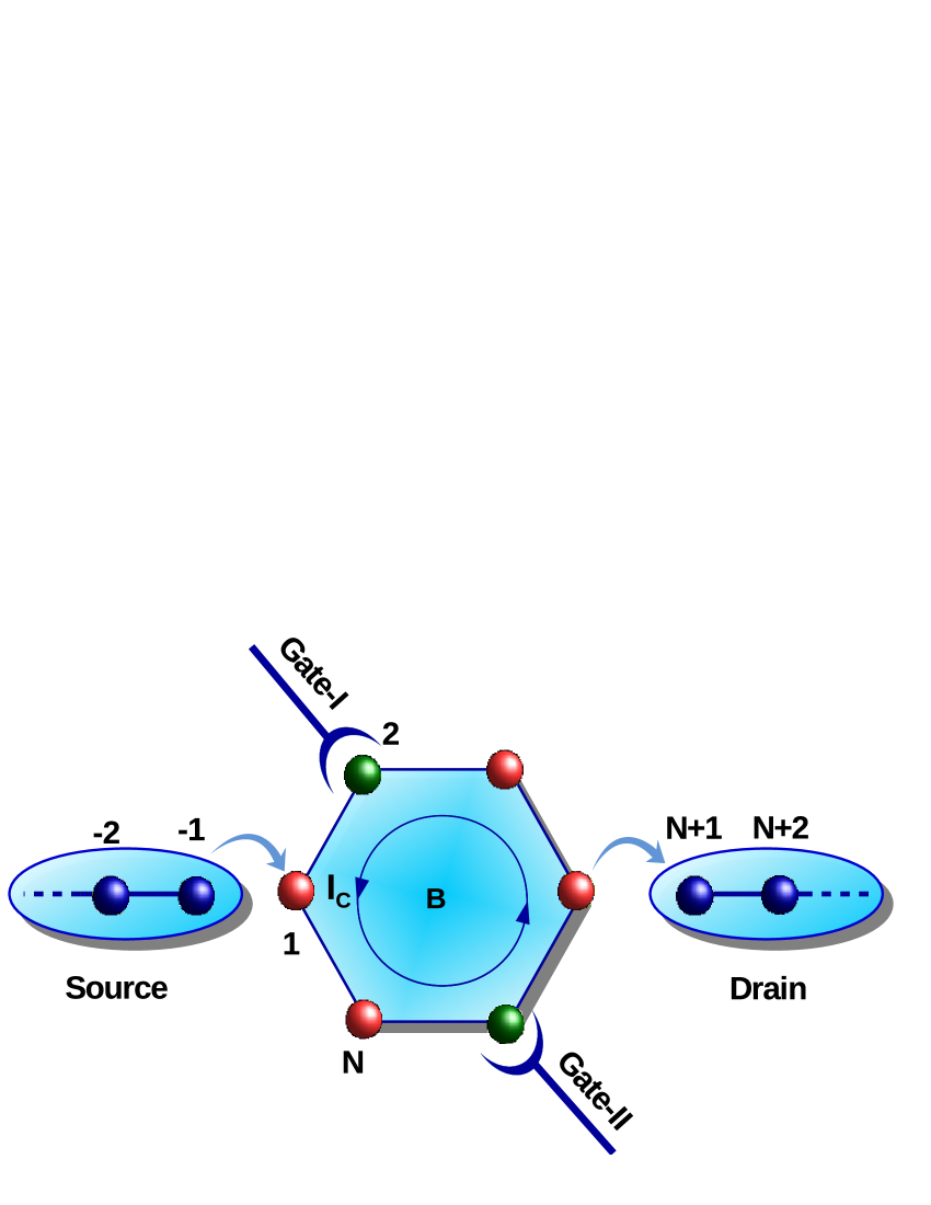
Let us begin with the model molecular junction shown in Fig. 1 where a benzene molecule is sandwiched between source (S) and drain (D) electrodes. These electrodes are assumed to be perfect, one-dimensional and semi-infinite, and they are coupled to the phenyl ring symmetrically (upper and lower arms have equal lengths) to form a lengthwise symmetric molecular junction. As already mentioned that to get circular current we need to break symmetry between the two arms for this lengthwise symmetric junction which we do by altering the status of a single atomic site or more sites depending upon the requirement of logic functions. Two different status are enumerated by two filled colored sites (green and red), where the filled red circles correspond to the parent lattices having a specific site energy and the other circles (i.e., green circles) have another site energy, and this change of site energy is done by means of gate electrode.
The full system is modeled by a tight-binding (TB) framework and the Hamiltonian becomes
| (1) |
where represents the molecular Hamiltonian, and are the Hamiltonians for the S and D electrodes, and the Hamiltonian is associated with the coupling of the molecule with side-attached electrodes. All these Hamiltonians are described by a similar kind of TB form and within non-interacting picture the general form of Hamiltonian reads as cir1 ; cir3
| (2) |
where , , and as used in Eq. 1. The parameters and describe the site-energy and nearest-neighbor hopping (NNH) integral, respectively, and , are the Fermionic operators. Now, depending on different parts of the molecular junction we use different symbols of site energy and NNH integrals. For the two perfect electrodes these are and , respectively, while for the molecule, having six atomic sites, these parameters are and , respectively. The molecular ring is coupled to S and D through the coupling parameter and , respectively, and these are responsible for the tunneling of electrons between the molecule and electrodes.
This is all about the Hamiltonian of our system. Now, in order to explore logical operations and storage mechanisms first we need to calculate bias induced circular current, and we do it by using wave-guide theory cir1 ; cir2 ; cir3 ; wg1 ; wg2 ; wg3 , a standard method of studying electron transport through a conducting junction. In this prescription a set of coupled linear equations involving wave amplitudes at different lattice sites of the molecule are solved those are generated from the Schrödinger equation
| (3) |
where . ’s are the wave amplitudes and ’s are the Wannier states. Assuming plane wave incidence from the source electrode with unit amplitude we can write the wave amplitude at any particular site (say) of S as , where is the wavevector and it is determined from the relation ( being the lattice spacing). is the reflection coefficient. For the drain electrode the wave amplitude at any particular site (say) becomes quite simpler as there is no reflection from the drain end and gets the form , where is the transmission coefficient, and, its absolute square gives the transmission probability. Using the above wave forms of incident and transmitted waves, we solve the coupled linear equations involving wave amplitudes at different lattice sites for different injecting electron energies, and then we calculate bond current density between any two neighboring sites (say, and ) of the molecule following the expression cir1 ; cir3 ; wg1
| (4) |
Integrating this current density we compute bond current for a particular bias voltage and it becomes cir1 ; cir3 ; datta
| (5) |
where is the equilibrium Fermi energy. Once the bond current is evaluated, the net circular current in the molecular ring is obtained from the relation cir1 ; cir3 ; sm1 ; sm2
| (6) |
where () describes the circumference of the molecular ring geometry and corresponds to the total number of atomic sites in it. The circular charge current can be positive or negative as well depending on bias regimes, unlike transport charge current which is always positive. We assign positive sign for the circular current flowing in the counter-clockwise direction. Thus, for a lengthwise symmetric molecular junction when the status of the upper and lower arms are exactly identical, equal currents pass through these arms but they propagate in opposite directions which leads to a vanishing circular current. We refer it as OFF state for the logical operations. On the other hand, for the asymmetric conditions currents in different arms are no longer identical which results a finite and we define it as ON state of the output. The non-zero circular current produces a magnetic field , and we can easily calculate it () at any desired point by using Biot-Savart’s law cir1 ; cir2 ; cir3 ; sm1 ; sm2
| (7) |
where is the position vector of the current element , and ( NA-2) is the magnetic constant. To calculate magnetic field we need to take the sum over all bonds of the molecular ring. This circular current induced magnetic field may be utilized for storage mechanism as well, as we discuss below.
For the entire discussion we set the system temperature at absolute zero, for simplification, and no physics will be altered at all at finite (low) temperatures since the system size is too small which yields much higher average spacing of energy levels and at the same time the thermal energy broadening is extremely small compared to the broadening caused by the molecule-to-electrode coupling datta .
III Numerical Results and Discussion
In what follows we present our results. Before scrutinizing the individual logical operations along with storage functions, based on the mechanism of bias induced circular current under two input conditions, we explore the general features of circular current in the molecular ring. In order to explore it, let
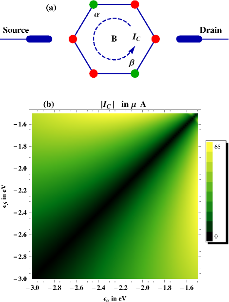
us start with the setup given in Fig. 2(a) where the input signals are applied to the filled green circles marked as and sites. These two sites get two different energies, referred as and , compared to the parent lattice sites (shown by the filled red circles) whose site energies are parameterized by as mentioned earlier in theoretical prescription. For this typical junction setup (Fig. 2(a)), the dependence of circular current on and is shown in the lower panel of Fig. 2 (Fig. 2(b)).
We tune and in a wide range starting from eV to eV, and interestingly we find that the circular current completely vanishes whenever matches with for this lengthwise symmetric molecular junction. Whereas, finite is observed under the condition , and it () reaches to a maximum when the difference between these two inputs are maximum. The above facts can be explained clearly by incorporating the concept of symmetry between the upper and lower arms of the molecular junction. When , both these two arms are physically identical, and therefore, the currents passing through these arms are equal in magnitude but as they traverse in the opposite directions the net circular current vanishes. Naturally, a finite current appears only when the symmetry between the two arms is broken, and that is done by making the site energies of the two green sites unequal. The underlying physics of getting circular current (resultant of individual bond currents, see Eq. 6) is that at least one molecular energy level has to appear within the bias window for which we are interested to get circular current. With increasing this voltage window, more energy levels may appear and all of them contribute to the current (both positive and negative currents are highly expected). Eventually the net response is determined by the dominating energy levels. So, naturally, we can expect both the two signs of this current, unlike the transport charge current which always be positive. As for the logical operations we are not bothering about the sign of the current , in Fig. 2(b) we take the absolute values of to have a clear idea of this density plot. The other notable thing is that the amount of circular current is too high (few microamperes) which induces a strong enough magnetic field (milliTesla) at and away (not too far) from the ring center.
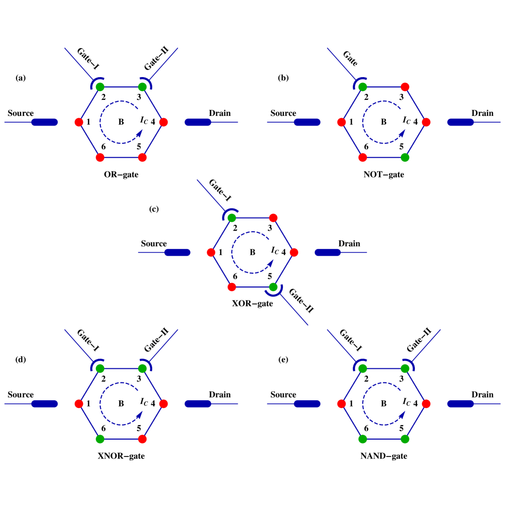
This is the basic concept of circular current that is utilized to explore different logical operations, and below we characterize them. In this communication we are able to explore total five logic gates (OR, NOT, XOR, XNOR, NAND) based on the idea of bias induced circular current and the sketches for designing these gates are shown in Figs. 3(a) to (e), respectively. Two gate electrodes (Gate-I and Gate-II) are used for two-input logic gates, while a single such electrode is used for the one-input logic gate (i.e., for NOT gate). Applying a suitable gate voltage we tune the site energies (, ) of the atomic sites placed in the vicinity of gate electrodes. When the gate is ON, the site energy becomes eV, while in the OFF state this energy becomes identical to the parent lattice sites which is fixed at eV. These two site energies are considered as the ON and OFF states of an input signal. Now, in addition to this, in some cases (NOT, XNOR, and NAND) we include green site(s) whose energy is fixed at eV for the entire operation. To set this energy we also use an external gate electrode, like other cases, but as it is not changed we do not show the image of extra gate electrodes in our schematic diagrams, not to make them clumsy. These additional green sites (for the NOT and XNOR gates the number of extra green sites is one, while for the XNOR gate this number is two) are required to achieve definite logical operations following the symmetry conditions. With these propositions now the logical operations can be clearly understood from the distinct sketches shown in Fig. 3(a)-(e). Their output responses are presented in Table 1 for the quantitative treatment. Looking into the data given in Table 1 we see that, in each case quite large circular
Input Input Output NOT I II OR XOR XNOR NAND Input Output 0 0 0 0 52.5 682.2 0 52.5 0 1 52.5 52.5 0 48.7 1 0 1 0 52.5 52.5 0 48.7 1 1 686.2 0 48.7 0
current appears in the ring when the output signal is ON. It suggests an easy detection of by some indirect means ind1 as the response involving will be large enough to measure. For the OFF state, no such response will be available. In the same footing, the large induces a considerable magnetic field (few orders of milliTesla) at the ring center as well as in its close vicinity. The strength of magnetic field, associated with circular current , can easily be estimated from the relation given in Eq. 7. Defining as the perpendicular distance from the centre of the benzene molecule to any - bond, the magnetic field at the ring center can be expressed as . Thus, for the average circular current (say) A (see Table 1), the induced magnetic field (considering nm cir2 ) becomes mT which is too large than the required magnetic field to operate a single spin, and it can be understood clearly from the following analysis. It is well known that with the application of magnetic field the orientation of a spin can be regulated selectively. For rotating a single spin by a relative angle within a time scale , the required magnetic field is lidar : , where is the Bohr magneton and represents the -factor. Thus, to rotate a spin by an angle , assuming the average operation time ns, the desired magnetic field is mT lidar , which is too small compared to the obtained average magnetic field mT in the molecular ring. The above arguments essentially motivate us to recommend two separate schemes for storage mechanism using our molecular system. One is charge based which is our primary goal along with logic functions, and the other is the spin based. The ideas are as follows. For the charge based device, we mark for finite , while it becomes when completely disappears. Since this current is non-volatile, the information can definitely be stored even when the power is off. For the other prescription i.e., spin-based, we can place a free magnetic site either at the center of the molecular ring or away (not so far) from the ring plane whose magnetic moment direction can be tuned by means of circular current induced magnetic field cir2 ; mm1 . Assigning the free moment direction (not along -direction, say in the - plane) as for the case when , and its direction along -axis as due to the interaction of magnetic moment with field for finite , we can define two separate states of logic bits. As the induced magnetic field is reasonably high, it can easily tune a magnetic moment lidar which is not aligned initially along -direction, and we strongly believe that this prescription can be substantiated.
Before we end the discussion, we would like to state that the results studied here are worked out for a typical set of parameter values. But all these results are equally valid for any other set of parameter values which proves the robustness of our analysis.
IV Closing Remarks
We conclude by pointing out that a single benzene molecule (or any other cyclic molecule having even number of sites, though smaller rings are always appreciable as they can produce large circular current) is capable of performing different logical operations and can be programmed and re-programmed for suitable functional operations. Our proposal leads to a significant impact in designing charge based storage device along with functional logical operations.
V Acknowledgment
MP gratefully acknowledges UGC, India (F. 2-10/2012(SA-I)) for providing her doctoral fellowship.
References
- (1) A. P. de Silva, H. Q. N. Gunaratne, and C. P. McCoy, A molecular photoionic AND gate based on fluorescent signalling. Nature 364, 42 (1993).
- (2) F. M. Raymo, Digital processing and communication with molecular switches. Adv. Mater. 14, 401 (2002).
- (3) A. P. de Silva et al., Signaling recognition events with fluorescent sensors and switches. Chem. Rev. 97, 1515 (1997).
- (4) Y. Huang et al., Logic gates and computation from assembled nanowire building blocks. Science 294, 1313 (2001).
- (5) S. Kou et al., Fluorescent molecular logic gates using microfluidic devices. Angew. Chem. 120, 886 (2008).
- (6) D. Wang et al., Molecular logic gates on DNA origami nanostructures for microRNA diagnostics. Anal. Chem. 86, 1932 (2014).
- (7) M. Patra and S. K. Maiti, Logical operations using phenyl ring. Phys. Lett. A 382, 420 (2018).
- (8) H. Dery, P. Dalal, Ł. Cywiński, and L. J. Sham, Spin-based logic in semiconductors for reconfigurable large-scale circuits. Nature 447, 573 (2007).
- (9) A. Ney, C. Pampuch, R. Koch, and K. H. Ploog, Programmable computing with a single magnetoresistive element. Nature 425, 485 (2003).
- (10) R. Richter, L. Bär, J. Wecker, and G. Reiss, Nonvolatile field programmable spin-logic for reconfigurable computing. Appl. Phys. Lett. 80, 1291 (2002).
- (11) B. Behin-Aein, D. Datta, S. Salahuddin, and S. Datta, Proposal for an all-spin logic device with built-in memory. Nature Nanotech. 5, 266 (2010).
- (12) S. A. Wolf et al., Spintronics: A spin-based electronics vision for the future. Science 294, 1488 (2001).
- (13) Editorial. Memory with a spin. Nature Nanotech. 10, 185 (2015).
- (14) D. Rai, O. Hod, and A. Nitzan, Circular currents in molecular wires. J. Phys. Chem. C 114, 20583 (2010).
- (15) D. Rai, O. Hod, and A. Nitzan, Magnetic fields effects on the electronic conduction properties of molecular ring structures. Phys. Rev. B 85, 155440 (2012).
- (16) M. Patra and S. K. Maiti, Modulation of circular current and associated magnetic field in a molecular junction: A new approach. Sci. Rep. 7, 43343 (2017).
- (17) L. P. Levy, G. Dolan, J. Dunsmuir, and H. Bouchiat, Magnetization of mesoscopic copper rings: Evidence for persistent currents. Phys. Rev. Lett. 64, 2074 (1990).
- (18) H. F. Cheung, Y. Gefen, E. K. Riedel, and W. H. Shih, Persistent currents in small one-dimensional metal rings. Phys. Rev. B 37, 6050 (1988).
- (19) S. K. Maiti, M. Dey, S. Sil, A. Chakrabarti, and S. N. Karmakar, Magneto-transport in a mesoscopic ring with Rashba and Dresselhaus spin-orbit interactions. Europhys. Lett. 95, 57008 (2011).
- (20) S. K. Maiti, Determination of Rashba and Dresselhaus spin-orbit fields. J. Appl. Phys. 110, 064306 (2011).
- (21) M. Patra and S. K. Maiti, Unconventional low-field magnetic response of a diffusive ring with spin-orbit coupling. Phys. Lett. A 381, 221 (2017).
- (22) R. Baer and D. Neuhauser, Anti-coherence based molecular electronics: XOR-gate response. Chem. Phys. 281, 353 (2002).
- (23) R. Baer and D. Neuhauser, Phase coherent electronics: A molecular switch based on quantum interference. J. Am. Chem. Soc. 124, 4200 (2002).
- (24) Y. J. Xiong and X. T. Liang, Fano resonance and persistent current of a quantum ring. Phys. Lett. A 330, 307 (2004).
- (25) Y. Shi and H. Chen, Transport through an Aharonov-Casher ring with a quantum gate. Phys. Rev. B 60, 10949 (1999).
- (26) C. M. Ryu et al., Quantum waveguide theory for triply connected Aharonov-Bohm rings. Int. J. Mod. Phys. B 10, 701 (1996).
- (27) S. Datta, Electronic transport in mesoscopic systems. Cambridge University Press, Cambridge (1997).
- (28) S. K. Maiti, Externally controlled local magnetic field in a conducting mesoscopic ring coupled to a quantum wire. J. Appl. Phys. 117, 024306 (2015).
- (29) S. K. Maiti, Conformation-dependent electron transport through a biphenyl molecule: Circular current and related issues. Eur. Phys. J. B 86, 296 (2013).
- (30) T. Heine, C. Corminboeuf, and G. Seifert, The magnetic shielding function of molecules and Pi-electron delocalization. Chem. Rev. 105, 3889 (2005) and references therein.
- (31) K. Tagami and M. Tsukada, Current-controlled magnetism in T-shape tape-porphyrin molecular bridges. Curr. Appl. Phys. 3, 439 (2003).
- (32) D. A. Lidar and J. H. Thywissen, Exponentially localized magnetic fields for single-spin quantum logic gates. J. Appl. Phys. 96, 754 (2004).