Brokering Policies and Execution Monitors for IoT Middleware
Abstract.
Event-based systems lie at the heart of many cloud-based Internet-of-Things (IoT) platforms. This combination of the Broker architectural style and the Publisher-Subscriber design pattern provides a way for smart devices to communicate and coordinate with one another. The present design of these cloud-based IoT frameworks lacks measures to (i) protect devices against malicious cloud disconnections, (ii) impose information flow control among communicating parties, and (iii) enforce coordination protocols in the presence of compromised devices. In this work, we propose to extend the modular event-based system architecture of Fiege et al., to incorporate brokering policies and execution monitors, in order to address the three protection challenges mentioned above. We formalized the operational semantics of our protection scheme, explored how the scheme can be used to enforce BLP-style information flow control and RBAC-style protection domains, implemented the proposal in an open-source MQTT broker, and evaluated the performance impact of the protection mechanisms.
1. Introduction
The Internet of Things (IoT) is envisioned to be a massively distributed system of smart devices, each potentially equipped with physical sensors and actuators. This is, however, not the first day we develop distributed systems. Decades of experiences in architecting distributed systems have gone into the design of IoT frameworks. Specifically, the Broker architectural style has been employed to coordinate the communication between devices, so that the idiosyncrasies of low-level network communications can be abstracted away (buschmann, ). The Publisher-Subscriber design pattern has been applied to prevent the need for polling the state of collaborating devices, and to provide decoupling between message senders and receivers (buschmann, ). In this work, we use the term event-based systems to refer to this combination of Broker and Publisher-Subscriber (Fiege-etal:2002:KRR, ). Many existing IoT frameworks are essentially variants of event-based systems. The MQTT protocol, a messaging transport protocol widely used in popular IoT frameworks (including that of IBM, Amazon, and Microsoft), is an example of such a design (Mosquitto, ).
The implementation of event-based systems in the context of commercial IoT frameworks, however, has a twist, and that is the centralization of the notification mechanism on a cloud platform. This is understandable as a cloud-based implementation offers the benefit of low configuration and maintenance cost.
The motivation of this work is to inquire about what unique protection challenges are presented in the cloud-based realization of event-based systems, and to devise protection mechanisms and access control technologies for addressing them. We discern three protection challenges.
-
(1)
Cloud disconnection. Previous work has argued that a cloud-based implementation of an IoT coordination framework could be susceptible to cloud disconnection (Tam, ). That is, the cloud could be disconnected because it has fallen victim to a DDoS attack, or the ISP becomes unavailable because of an Internet-scale incident, or the physical connection to the cloud is maliciously severed.
-
(2)
Information flow control. Some of the messages exchanged by devices are sensitive. The nature of a Publisher-Subscriber system is that the two parties of communication need not know one another. Such decoupling must be complemented by proper information flow control in order that messages are not accidentally received by unintended parties. This need for privacy and confidentiality is particularly relevant in the era of ubiquitous deployment of sensors, which collect personal information from health data to what goes on in the bedroom.
-
(3)
Enforcing coordination protocols. Smart devices are limited in capability, and thus they are easy targets for malicious exploits. Yet these devices are now part of our safety infrastructure. An example is to have the smoke detector shut down the furnace in the event of a fire. If these devices are compromised, then the coordination logic that we rely on to ensure safety will no longer be carried out properly. It is therefore important to build measures into the event-based systems so that any deviations from coordination protocols can be detected, and, if possible, compensated for.
This work proposes a unified protection scheme that addresses the aforementioned challenges in event-based systems. More specifically, the following are our contributions.
-
(1)
We adopted the modular event-based system of Fiege et al (Fiege-etal:2002:SAC, ; Fiege-etal:2002:ECOOP, ; Fiege-etal:2002:KRR, ; Muhl-etal:2006, ), which is made up of multiple communicating brokers, to mitigate the impact of cloud disconnection (§3). More importantly, we extended their work, and introduced the ideas of imposing brokering policies to control the flow of information among brokers and devices (§4.1), and interposing execution monitors along network links to enforce coordination protocols (§4.2). We demonstrated the utility of our proposal in a case study that shows how the proposed protection mechanisms can be deployed to protect a smart home (§4.3).
-
(2)
We formalized the operational semantics of our protection scheme in the form of a state transition model (§5). This lays the foundation for the study of policy enforceability in the context of event-based systems.
-
(3)
We devised a number of usage patterns that allow one to impose BLP-style information flow control and RBAC-style protection domains in the context of an event-based system (§6).
- (4)
2. Related Work
This work builds on the modular event-based system architecture of Fiege et al. (Fiege-etal:2002:SAC, ; Fiege-etal:2002:ECOOP, ; Fiege-etal:2002:KRR, ; Muhl-etal:2006, ), but moves significantly beyond it. The adoption of multiple brokers is no longer motivated by modularity, but for anticipating cloud disconnection. Brokering policies are generalization of the Fiege et al. scoping rule (§3). Execution monitors are generalization of event filters and mappers (§6.2).
Cloud disconnection is addressed in (Tam, ) by having a local hub that replicates the coordination scripts that are stored in the cloud. Our work can be seen as a more principled and general way to localize coordination logics. Virtual objects are software shadows of physical devices (Alshehri-Sandhu:2016, ; Alshehri-Sandhu:2017, ). Having virtual objects hosted in the cloud partly addresses the problem of occasional cloud disconnections, but this does not guarantee the proper functioning of coordination logics when the cloud is disconnected. Pushing security enforcement towards the edge of the network is a general trend (Sicari-etal:2017, ; Phung-etal:2017, ). Our work provides a general architecture for hosting safety-related coordination logics at the edge in anticipation of cloud disconnection.
There has been growing interests in applying Attribute-Based Access Control (ABAC) (ABAC, ) in the context of IoT in general, and event-based systems in particular (Sciancalepore-etal:2016, ; Rizzardi-etal:2016, ; Gabillon-Bruno:2018, ; Colombo-Ferrari:2018, ). Our work is complementary. For example, ABAC can be deployed to control which devices can be connected to the various brokers in a broker ensemble. Each broker plays the role of a protection domain. Information flow control (§6.1.1) and history-tracking execution monitors (§4.2) can then be employed to control the routing and transformation of events among protection domains (brokers). This is the setup envisioned in §6.2.3. Note that when we use the RBAC terminology of (rbac-middleware, ) in §6.2.3, we are not sanctioning RBAC for IoT. The so-called “roles” are but protection domains.
Also relevant to this work are attempts to add content-based access control to MQTT (Colombo-Ferrari:2018, ). A technical challenge is to meet the hungry throughput demand of IoT applications. Our implementation of history-tracking execution monitors is a first step towards realizing high-throughput, content-based event processing in a messaging system (§7–8).
3. Background: Multiple Brokers
Distributed Event-Based Systems.
A popular system architecture for IoT applications is to have devices connected to a cloud-based broker. Typically a device signals a change of its state by publishing a message, also known as a event, through the broker. Each event is typically annotated with an event topic, which is a tag that allows the broker to quickly classify events for the purpose of message delivery. Devices may also declare to the broker what event topics they are interested in. This declaration of interest is also known as a subscription. On receiving an event published under a certain event topic, the broker will notify all the devices that have previously subscribed to that event topic. The rationale for adopting such an architecture in a distributed system is so that devices are decoupled from one another: the publisher does not need to know who will end up receiving a message, and a subscriber does not need to know from where the event originates. The broker is the only one who needs to know the network addresses of the communicating parties. In addition, subscription-based notification eliminates the need for periodic polling. This architectural design, in which the broker architecture style is combined with the publisher-subscriber design pattern (buschmann, ), is known in the literature as an event-based system (Fiege-etal:2002:KRR, ). MQTT, a popular messaging transport protocol designed for IoT applications, is a typical instantiation of this system architecture (MQTT, ).
Cloud Disconnection.
Previous work has argued that an IoT framework that is built around a centralized, cloud-based broker is susceptible to cloud disconnection (Tam, ). The latter could be caused by, for example, the cloud infrastructure becoming the victim of a DDoS attack, the network infrastructure of an Internet Service Provider (ISP) being affected by an internet outage event, or a malicious party physically severing the connection between the devices and the cloud-based broker. Such disconnections could have physical safety implications. For example, the cloud-based broker typically hosts coordination logics that notify one device when the state of another device changes. Such coordination logics could very well be part of the measures for ensuring physical safety: e.g., notify homeowner in case of break-in, shutdown furnace in case smoke is detected, unlock door for helper in case an elderly occupant is found to have fallen on the ground, etc. If the cloud is maliciously disconnected, then the coordination logics hosted on the cloud will not be executed. This could have potentially serious safety implications.
Enter Multiple Brokers.
To anticipate cloud disconnection, previous work has argued that redundancy must be built into an IoT framework (Tam, ). In other words, it is desirable to ensure that coordination logics are still executed in the event of cloud disconnection.
The modular event-based system architecture of Fiege et al. (Fiege-etal:2002:SAC, ; Fiege-etal:2002:ECOOP, ; Fiege-etal:2002:KRR, ; Muhl-etal:2006, ) provides a good starting point for anticipating cloud disconnection. The system design of Fiege was originally proposed for the sake of modularizing distributed event-based systems, in this work we reappropriate their design for building resiliency into an IoT framework so as to mitigate the impact of cloud disconnection. Ultimately, we will move beyond their proposal (see §4).
In the system architecture of Fiege et al., there are multiple brokers connected to one another through network connections. When a device publishes an event to a broker, the latter does not only notify the subscriber devices who are connected directly to itself, but also passes the event to its neighbouring brokers. This propagation of message publication is further regulated by two mechanisms.
-
(1)
The design goal of Fiege et al. is to provide modularity in the construction of distributed systems. Consequently, they envisioned that each broker is the physical embodiment of a namespace of events. Recall that namespace management is the classical means for adding modularity to a programming language environment. Influenced by this programming language root, Fiege el al. called these namespaces scopes. To support nested scoping (as in a structured programming language), they did two things. First, they organized the brokers into a hierarchy. Second, they imposed a scoping rule on the propagation of events from one broker to another.
- The Fiege et al. Scoping Rule.:
-
An event published in a broker is visible to the subscribers in broker only if there exists a broker that is a common ancestor of both and in the broker hierarchy. A degenerate case is when is either or .
For example, in Fig. 1, an event published by device to broker will be visible to subscriber under broker and also subscriber under broker . The latter case is justified by being a common ancestor of and . On the contrary, subscribers under broker will not be notified, as does not share a common ancestor with .
The scoping rule above can be implemented by a simple modification to the broker. In particular, if an event is propagated to a broker from one of its parents, then will not propagate the event to its other parents. For example, in Fig. 1, broker will not propagate to parent broker those events received from parent broker .
-
(2)
To push the scoping metaphor further, Fiege et al. also introduced event filtering and event mapping into the event propagation mechanism. Event filtering refers to a mechanism that allows the system architect to specify that events of certain topics are not permitted to be propagated along a network connection linking one broker to another. This promotes encapsulation, and thus allows certain event topics to become private within a scope (i.e., a broker). Event mapping refers to a mechanism that allows the system architect to specify how event topics are “renamed” (to other topics) as they pass through a network connection linking one broker to another. This further promotes encapsulation.
The introduction of multiple brokers offers a good starting point for anticipating cloud disconnection. For example, in Fig. 1, if broker is disconnected, then other brokers can still perform local propagation of events. We envision that brokers are organized based on their network proximity to the devices. For example, a local hub can connect devices belonging to the same local area network. Then an ISP may host a broker for each geographical region it serves. Such a broker will be the parent of the local hubs. A cloud service provider then provides a top-level broker, with ISP brokers as children. Other intermediate level brokers can be introduced as needed (e.g., brokers mirroring organizational divisions). Coordination logics hosted at one level of the hierarchy will not be affected by the disconnection of brokers at a higher level.
4. Overview of Protection Scheme
While the introduction of a broker hierarchy does serve as a good starting point for protecting an IoT framework against malicious or accidental cloud disconnection, it is the position of this work that the scoping rule and event filtering/mapping of Fiege et al. do not go far enough for addressing the access control needs of an IoT framework, we therefore propose two additional protection features in this work.
-
(1)
Controlling flow of information. While encapsulation allows the system architect to better reason about the behavior of individual distributed software components and compose them together with ease, it does not allow the security architect to impose finer-grained control of information flow within the broker ensemble. Certain brokers may host devices that publish sensitive messages (e.g., a broker that are connected to sensors in the master bedroom of a smart home), and thus the security architect may want to make sure that such events are received only by a selected group of authorized devices. One way to achieve this is to control the information flow paths in the broker ensemble. To this end we propose a generalization of Fiege et al.’s architecture, so that arbitrary brokering policies can be imposed on the broker ensemble to control information flow paths. The scoping rule of Fiege et al. becomes a special case of these brokering policies.
-
(2)
Enforcing collaboration protocols. When devices collaborate with one another, there are typically well-understood collaboration protocols that they have to follow. Unfortunately, IoT devices have limited capabilities, and thus they are easy to compromise. In fact, we should take as an axiom that they will be compromised sooner or later. Compromised devices may not follow the intended collaboration protocol, and thus the integrity of the collaboration will be destroyed. We propose an extension of Fiege et al.’s architecture, so that execution monitors can be put in place to detect violation of the collaboration protocol, or even enforce the protocol by modifying the message exchanged by the devices. The event filtering and event mapping features of Fiege et al.’s architecture become special cases of execution monitors.
4.1. Configurable Brokering Policies
Rather than having a fixed scoping rule to regulate how events are propagated among brokers, our scheme allows the security architect to impose arbitrary brokering policies. A brokering policy is a system-wide scheme for deciding how each broker is to forward events. The broker ensemble is no longer organized as a hierarchy. Instead, brokers are peers that propagate events in accordance to the brokering policies. A brokering policy is composed of the following elements.
-
(1)
When two brokers (or a device and a broker) are connected to one another, we treat each direction of communication a distinct network link. Each network link is assigned a link type. These link types are domain specific, and the security architect can choose to create link types that are relevant to the application domain in question. For example, when we model Bell-LaPadula (BLP)-style information flow control, a link type could be “confidential”, indicating that the events passing through the network links with this label carry confidential information (§6.1.1). Alternatively, to model the Fiege et al. broker hierarchy, a network link from a child broker to a parent broker can be associated with the link type “up” (§6.1.2).
-
(2)
A brokering table, which is replicated to all the brokers, specifies if a broker may forward an event that it receives from a network link of type to a network link of type . In short, the brokering table is an table of boolean values, where is the number of link types.
As we shall see, the provision for configurable brokering policies allow the security architect to control the information flow paths in the broker ensemble (§6.1.1).
4.2. History-Tracking Execution Monitors
Rather than imposing an event filter or an event mapper along network links, our scheme allows arbitrary execution monitors to be interposed along network links. An execution monitor intercepts every event moving along a network link, and responds by (a) suppressing the event, (b) leaving the event as is, or (c) transforming the event to another sequence of events. Note that option (c) may involve injecting new events into the network link. More importantly, an execution monitor is stateful, thereby enabling the execution monitor to enforce History-Based Access Control (HBAC) policies (Evans-Twyman:1999, ; Schneider:2000, ; IRM, ; Wallach-etal:2000, ; Fong:2004, ; Krukow-etal:2008, ; EA:IJIS, ; EA:TISSEC, ). This history-tracking feature of an execution monitor is the key to enforcing collaboration protocols among devices (§4.3). We will demonstrate that event filtering and event mapping are but special cases for our execution monitors (§6.2).
Let us make these notions formal. Let be an alphabet of events. (More precisely, these are event topics. We identify events by their event topics when the event payloads are not our focus.) We use , and to denote members of , and write , and to denote members of .
Ligatti et al. proposed the edit automaton (EA) as an abstract model of execution monitors. An edit automaton transforms a sequence of events generated by an untrusted program to another sequence of events that is safe for the observer to consume (EA:IJIS, ; EA:TISSEC, ). The idea is that certain event sequences may damage the integrity of the observer, and thus to protect the observer those sequences are “rewritten” to a benign form. We have adapted their definition to a form that is readily implementable. More specifically, we define an edit automaton (EA) to be a quadruple , such that is a finite set of symbols, is a countable set of states, and is the initial state, and is the transition function (NB: a total function). Given a current state and an input symbol , is a pair , where is the next state, and is a sequence of output symbols generated by the transition. If the output sequence is empty (i.e., ), then the input event is “suppressed.” can also function as an event mapper: that is when the output sequence is a single symbol , meaning that replaces the input event by an output event . Lastly, may also inject events: that is when has multiple events.
In the rest of this paper, we may draw transition diagrams to represent an edit automaton (Fig. 3 and 4). When we do so, the following convention is used.
Convention 1.
The following conventions are followed when the transition diagram of an edit automaton is drawn. (1) The state labelled is the initial state. (2) If the label “” appears on a transition edge from state to , then that transition will be triggered on input event , and the latter is transformed into the output event sequence (i.e., ). (3) We write “” as a shorthand for the transition label “” (i.e., is preserved). (4) We write “” as a shorthand for the transition label “” (i.e., is suppressed). (5) If the labels “”, “”, or “” appear on a transition edge from to , then they mean “”, “”, and “” respectively for every event that does not appear on any transition edge emanating from . (6) If none of the labels “”, “”, or “” appears on any transition edge emanating from , then implicitly there is a transition edge from to itself, with the label “”.
4.3. Case Study
We illustrate the use of our proposed architecture by an example smart home configuration.
A Smart Home.
The home owner has installed the following devices: a motion detector (MD), a security camera (SC), a door lock (DL), and a door bell (DB). In addition, the home owner carries a smart phone (SP).
Suppose all devices are connected to a centralized, cloud-based broker. For brevity, we identify an event by its topic in the following discussion. The normal flow of events is listed below:
-
(1)
MD is used for detecting if someone is currently at home. MD periodically announces its findings by publishing either MD_motion or MD_no_motion.
-
(2)
DB subscribes to MD_motion and MD_no_motion, and updates its internal state accordingly.
-
(3)
When a person presses DB, the latter checks its internal state to see if anyone is at home. If someone is home, then the following steps are skipped.
-
(4)
If no one is at home, DB will request SC to take a picture of the person at the door by publishing SC_request. Upon notification, SC will send a picture by publishing an SC_send event with the picture as the payload.
-
(5)
Upon receiving the picture, DB publishes an event with AC_request as its topic and the picture as its payload.
-
(6)
SP subscribes to AC_request. The home owner will examine the picture of the person at the door, and decide if access should be granted. If so, then SP will publish AC_grant. Otherwise, SP publishes AC_deny.
-
(7)
When DB receives an AC_grant, it will request DL to unlock the front door by publishing DL_unlock.
Policies.
We desire to enforce four policies in the smart home environment.
- Policy 1 (Resiliency Against Cloud Disconnection).:
-
If the cloud is ever disconnected, minimum services shall be available. For example, even though it is impossible to contact SP in the event of cloud disconnection, MD should still be able to update the internal state of DB.
- Policy 2 (Information Flow Control).:
-
Events with topics MD_motion and MD_no_motion are sensitive information, and shall not be leaked outside of the home for privacy sake.
- Policy 3 (Visibility Control).:
-
DL_unlock is a sensitive control signal, and should only be sent from within the home. Any DL_unlock event that is sent from the internet is discarded.
- Policy 4 (Collaboration Protocol).:
-
It is possible that some of the devices (e.g., DB) are compromised. We want to make sure that DL_unlock is published only as the last event in the sequence: AC_request, AC_grant, DL_unlock. Any deviation from this collaboration protocol is a sign that some of the devices have been compromised.
To enforce the policies stated above, the smart home is reconfigured according to Fig. 2. We explain the configuration below.
Enforcing Policy 1 (Resiliency Against Cloud Disconnection).
Notice that multiple brokers are introduced (Fig. 2). The broker is hosted in the cloud, which provides a point of contact to the SP. The broker is a gateway to the local network of the smart home. Broker and the home devices are connected to and to each other via a LAN. If the cloud is ever disconnected (i.e., the network links between and are severed), the rest of the broker ensemble will still be functional.
Enforcing Policy 2 (Information Flow Control).
As shown in Fig. 2, the network links are classified into three types: (a) sensitive, (b) door, and (c) internet. A global brokering policy is formulated in such a way that the following propagation is not allowed:
- Brokering Policy.:
-
Events received from a link of type sensitive cannot be propagated to a link of type internet.
All other forms of propagation are allowed. The overall effect of this brokering policy is that MD_motion and MD_no_motion are not propagated by to , thus sensitive events remain inside the home.
Enforcing Policy 3 (Visibility Control).
We want to filter away any DL_unlock events that pass through the network link from broker to broker . This is achieved by placing an edit automaton along that network link (Fig. 2). The definition of is depicted in the transition diagram in Fig. 3, which preserves all events except for DL_unlock. Note two points. First, Policy 3 cannot be enforced by brokering policies, as we allow some events (e.g., AC_grant, see below) from broker to enter broker , but disallow others (e.g., DL_unlock) to do so. Second, since has only one state, Policy 3 does not exploit the history tracking feature of an edit automaton.
Enforcing Policy 4 (Collaboration Protocol).
Policy 4 is a history-based policy. Its enforcement requires the stateful tracking of event history. To this end, an EA is interposed along the network link from broker to broker (Fig. 4). permits the sequences “AC_request, AC_grant, DL_unlock” and “AC_request, AC_deny.” Any out-of-order occurrences of DL_unlock are suppressed. Notice that all events with topics AC_request, AC_grant, AC_deny, and DL_unlock will pass through , which in turn propagates them to . In this way, the collaboration protocol is enforced by before the events can reach DL. This protects the integrity of DL even if other devices are compromised. Note that the interposing of between and requires the system to track the automaton state.
In summary, we have demonstrated how the proposed protection scheme supports resiliency against cloud disconnection, information flow control, visibility control, and collaboration protocols.
5. Operational Semantics
This section presents the operational semantics of our proposed architecture in the form of a state machine model. Minor variants of this model have been “mechanized” using PLT Redex (PLT-Redex, ), a semantic engineering tool. The PLT Redex encoding of our state machine model consists of 820 lines of code, including both model definition and test cases. The mechanized model is executable. This exercise has allowed us to gain deeper insights into our formulation, and to catch a few errors in our early work. The mathematical formulation and the PLT Redex encoding lay the semantic foundation for future study of policy enforceability (see §9).
5.1. System Configuration
The configuration of an event-based system is captured in a (system) schema , which is a quadruple with the components below:
-
is a connection graph of the form :
-
–
and are two disjoint, finite sets of entities. is the set of devices, and is the set of brokers. We write to denote .
-
–
is a binary relation over entities. It represents network connections. The binary relation satisfies two additional requirements: (a) is symmetric but irreflexive; (b) .
Furthermore, induces four binary relations: (a) captures device-to-broker links, (b) captures broker-to-device links, (c) captures broker-to-broker links, and (d) captures links with a broker as the destination.
-
–
-
is the brokering policy, which is a structure of the form :
-
–
is a finite set of link types.
-
–
assigns a link type to each link.
-
–
is a binary relation defined over . If , then a broker is allowed to pass along an event it receives from a link of type to a link of type .
The brokering policy induces a ternary relation , so that iff , , and . That is, asserts that an event passing through link is allowed to be further propagated by the broker through the link .
-
–
-
The event policy is a quadruple :
-
–
, , and are the components of an EA. is the set of events (more precisely event topics) that can be transmitted in the event-based system.
-
–
assigns an EA transition function to each monitored link.
More specifically, the EA is the EA that transforms the events sent from to .
-
–
-
assigns a set of events to each broker-to-device link. Intuitively, is the set of events subscribed by device in broker .
-
is a partial ordering defined over the set of annotated tasks. Intuitively, the dynamics of the system is modelled as the generation and discharging of tasks. These tasks are “queued up” in a work list within the system state for further processing. A task is defined via the following grammar.
where , , and . We write for the set of all tasks defined for schema .
An annotated task is a construct of the form , in which the task is annotated with two timestamps (i.e., natural numbers), (i) , the generation time of , and (ii) , the generation time of the event publication task from which is derived. We write to denote the set of all annotated tasks for schema , and write for a typical member of .
By imposing the partial ordering over to indicate how tasks are prioritized, one can simulate different relative network speeds (see (Thesis, , §3.3.6) for examples). In particular, if , then will be processed before . The annotation of tasks allows to be formulated in terms of timestamps.
5.2. System States
Given a schema , a system state is a triple :
-
The system state tracks a global clock, for which is the current time. The clock is used within the model for producing timestamps.
-
is a function assigning an EA state to each link that is monitored by an EA. In particular, is the current state of , the EA guarding link .
-
The work list is a finite set of annotated tasks. In the following, the predicate asserts that is a minimal element in according to . Note that for a given there may be multiple annotated tasks satisfying the predicate. As usual, nondeterminism is implied in such cases.
Let be the set of all system states as defined above. We write to denote a typical member of . The initial state of a system is , where for every .
5.3. State Transition
Given a schema , we define a state transition relation . Intuitively, means that is a successor state of . The transition relation is defined by the following set of transition rules, which specify the condition under which , where , and . In the following specification, we follow the convention that by default , and , unless the rules explicitly say otherwise.
-
T-Publish. Generate an event publication task.
-
Precondition: , and .
-
Effect: .
-
-
T-Notify. Consume an event notification task.
-
Precondition: , , , and .
-
Effect: .
-
-
T-Deliver. Transmit an event over a link, and apply execution monitor to the transmitted event.
-
Precondition: , , , and .
-
Effect: Let and . Then , and , where:
-
-
T-Broker. Process a sequence of received events to create further transmissions.
-
Precondition: , , and , such that and .
-
Effect: Let . Then , where:
-
6. Usage Patterns
We explore how the two protection mechanisms, brokering control and execution monitoring, can be leveraged to impose various forms of access control policies in an event-based system.
6.1. Access Control with Brokering Policies
The most liberal brokering policy is , where is a singleton set , maps every link to , and . This trivial brokering policy allows every event received from a link to be forwarded to another link. This set-up is essentially the bridge feature of Mosquitto (Mosquitto, ): a bridge connects two MQTT brokers, so that the events received by one broker are made visible to the other broker. This liberal brokering policy, however, suffers from the following shortcoming. The brokers connected by bridges form a single scope of events. There is no regulation of what events are visible to which subscribers, making it difficulty to confine the visibility of sensitive events (e.g., personal health alerts). Imposing brokering policies more restrictive than allows us to regulate the flow of information, as we illustrate in the following.
6.1.1. Information Flow Control
Brokering policies allow us to impose a form of information flow control in the style of the Bell-LaPadula (BLP) model (BLP, ). The basic idea of the BLP scheme is that information sources (e.g., publishers) and information consumers (e.g., subscribers) are labelled with security labels (e.g., unclassified, confidential, secret, top secret). These security labels form a lattice structure, and is thus partially ordered. BLP is essentially an access control model that forbids “reading up” and “writing down” (Rushby, ). Information may only flow from “low” information sources to “high” information consumers.
In our context, an event publication is a “write,” and an event subscription can be considered a “read.” Rather than assigning security labels to entities, we opt for a more uniform and flexible approach, and assign security labels to links. The key idea is that when a broker receives an event from a link , is allowed to propagate the event to a subsequent link if the security label of the second link is at least as high as the security label of the first link. Consequently, the semantics of assigning a security label to a link is that events flowing through that link comes from sources with security labels lower than or equal to . When an event is transmitted through the system, it goes through links with monotonically increasing labels . More specifically, one can configure the brokering policy as follows to control the flow of information within the system.
-
Let be a partially ordered set of security labels.
-
The function assigns a security label to each link, in such a way that whenever . That is, a notification link of a device must have a security label no higher than the security label of every publication link of , In other words, the device is “reading down” through the notification link, and “writing up” through the publication link.
-
Define so that only if . That is, an event flowing through a link with a security label will only be propagated to a link with a security label at least as high as .
With the scheme above, successive links that transmit an event will have monotonically increasing security labels. We formalize this observation as follows.
A sequence of entities in is called a flow path if (a) for , (b) for , if , then and . A flow path is a flow route when none of the entities other than the two ends (i.e., , , …, ) is a device. A flow path is a potential path of information flow through the system. Intermediary entities along a flow path can be devices which read a message and then propagate information by publishing a correlated message. A flow route is a flow path for which the intermediary entities are all brokers.
With the way is defined, when a broker relays a message from link to link . Thus a message passes through links of monotonically increasing security labels as it travels through a flow route. A flow path is essentially the concatenation of flow routes for which the concatenation points are devices. The definition of ensures that monotonicity is preserved by such concatenation.
The administrator of the system may have some preconceived ideas about what flow paths (resp. routes) are permitted. An important validation task is to ensure that the configuration of the connection graph and the brokering policy does not violate her expectation. Given a connection graph , one can use a variant of the Floyd-Warshall algorithm (Algo, , §26.2) to compute whether there is a legitimate flow path between each pair of entities (more precisely, between each pair of links). Described in (Thesis, , Appendix A), the algorithm runs in time, where . The algorithm can be adopted to identify either flow paths or flow routes. Such an analysis allows us to debug the topology of the connection graph and the assignment of security labels, so as to ensure that devices that are supposed to communicate with one another can do so, and flow paths that are not supposed to exist are not accidentally enabled.
6.1.2. Component Architecture
The modular event-based systems proposed in (Fiege-etal:2002:SAC, ; Fiege-etal:2002:KRR, ) is the idea that brokers are organized into a hierarchy, so that each broker “glues” its children entities together to form a distributed software component. The Fiege et al. Scoping Rule of §3 provides a principled way for these hierarchically organized software components to communicate events with one another. We demonstrate in the following that such a scoping rule can be simulated using brokering policies.
We assume that the hierarchy is specified through a parenthood relation, . Intuitively, asserts that is a parent of . Two further restrictions apply to the specification of . First, a device is never a parent of any entity. Second, parenthood chains never form a cycle, not even a loop (i.e., a loop arises when an entity is its own parent).
Based on the given parenthood relation, the following brokering policy is formulated:
-
Let .
-
The function encodes the parenthood relation: if , and otherwise.
-
Define so that holds unless and . Effectively, a message can move “up” the hierarchy, and then “down”, but never move “up” after it has moved “down.”
The brokering policy above ensures that events published in a broker is visible to subscribers in another broker if and only if and share a common ancestor in the hierarchy. To see this, observe that a flow route from one device to another will only go from “up” to “down” but not vice versa. This essentially means that the flow route will first reach a common ancestor of the two devices before reaching its destination. Thus the sharing of a common ancestor determines visibility.
6.2. Access Control with Edit Automata
We have already seen in the case study of §4.3 that the history tracking feature of an edit automaton can be used for enforcing collaboration protocols (e.g., Policy 4) among a group of interacting devices. We do not further elaborate on this use.
Event filtering and event mapping are popular visibility control mechanisms in event-based systems. They are featured in the model of Fiege et al. (Fiege-etal:2002:ECOOP, ; Fiege-etal:2002:KRR, ), and implemented in Mosquitto (Mosquitto, ). We demonstrate that these two features are special cases of execution monitoring by edit automata. We then show how brokering policies can be combined with edit automata to simulate complex protection domains in event-based systems.
6.2.1. Event Filtering
Some events are used for coordination logics that belong to the internal working of a distributed software component. Publications of such events should not be visible outside of the component because of confidentiality considerations, and subscriptions of these events should not extend beyond the component boundary in order that external events do not affect the integrity of the component state.
Suppose is a subset of events that are allowed to pass through a link. Define the event filtering transition function so that if , and if . By setting ), only events in will be transmitted along the link.
Event filtering leads naturally to the notion of event “import” and “export” for component architectures such as the one presented in §6.1.2. A broker can present an interface to each parent broker . The interface consists of a set of events that is willing to import from , and a set of events is willing to export to . To achieve the above, we set , and .
6.2.2. Event Mapping
Event mapping is the transformation of events from one naming scheme to another naming scheme when they are transmitted along a link. Event mapping presents an alternative interface of a distributed software component to a client component, often for “gluing” purposes or for information hiding. Suppose is a function that renames events. Define the event mapping transition function such that . That is, the EA remains in state at all time, and output when the input event is . Setting to will cause all events passing through link to be renamed according to .
6.2.3. RBAC-style Protection Domains
In (rbac-middleware, ), a combination of publish/subscribe middleware and Role-Based Access Control (RBAC) (RBAC, ) is employed to control the events that clients (i.e., devices) are allowed publish and subscribe. The idea is that clients are assigned to roles, and membership in a role places limits on what events a client can publish, as well as what events it is allowed to subscribe to. Although the language of RBAC is used, a “role” here is essentially a protection domain in the event-based system. (We are not sanctioning RBAC for IoT!) We describe in the following how this model can be simulated by multiple brokers, brokering policies, and execution monitors.
We assume that the following RBAC policy is given: (1) a set of devices, (2) a set of roles, (3) a user-role assignment which specifies role membership, (4) a function specifying for each role the set of events that members of can publish, and (5) a function specifying for each role the set of events that members of can subscribe to. Based on the parameters above, we describe how one can construct a connection graph, a brokering policy, and edit automata to enforce the RBAC policy.
First, we introduce a set of brokers:
In short, we introduce two brokers, and , for each role . The intention is that clients belonging to role will publish events to the publication broker and subscribes to events through subscription broker . A distinguished broker is also introduced to perform message relaying among the publication and subscription brokers.
Second, the links between the entities are defined as follows:
The link set is the symmetric closure of , in which all publication and subscription brokers are connected to the broker , and every device belonging to role is connected to the brokers and .
Third, the following brokering policy is defined:
In short, an event can only travel from a device to a publication broker, then to broker , then to a subscription broker, and lastly to another device.
Fourth, edit automata that perform event filtering are imposed along every link from a publication broker to , and from to a subscription broker.
While the given RBAC policy can be simulated by the above broker ensemble, brokering policy, and execution monitors, two practical considerations remain.
First, it is important to ensure that only the devices who are members of role may connect to brokers and . For example, the MQTT broker implementation Mosquitto (Mosquitto, ) allows the administrator to set up a local ACL for each broker. Such an ACL can be used for encoding and enforcing role membership. More sophisticated access control paradigm, such as ABAC, can be used for authorizing a device into a role (i.e., a protection domain).
A second practical consideration is that, if a device belongs to multiple roles, it may end up receiving the same event multiple times. One way out is for the device to “activate” one role at a time, or “activate” a subset of roles for which the subscribable event sets are disjoint. In other words, even if a device belongs to multiple roles, it can connect to a subset of them in order to avoid repeated delivery of the same message.
An extension of the scheme is to support role hierarchies (i.e., hierarchical nesting of protection domains). The idea is that a senior role (more capable protection domain) inherits all the publishable events and subscribable events of its junior roles (less capable protection domains). This can be simulated readily by organizing the publication and subscription brokers hierarchically to mirror the role hierarchy.
7. Implementation
To evaluate the feasibility and the performance of brokering control and execution monitoring for distributed event systems, we have implemented a prototype of these two protection mechanisms in the open-source Mosquitto broker (Mosquitto, ; mosquittopaper, ) for the MQTT protocol (MQTT, ). MQTT is a messaging transport protocol that makes use of the Publisher-Subscriber design pattern to provide one-to-many message distribution and decoupling features (buschmann, ). It is used (or supported) widely in existing IoT frameworks, including the IBM Watson IoT platform, the Amazon AWS IoT platform, and the Microsoft Azure IoT platform.
Our implementation is based on the source code of Mosquitto version 1.4.10, the latest version when this work started. The “diff” between the original Mosquitto code base and our extension involves 1,426 lines of C code across 19 source files (including 7 new files we introduced into the code base).
7.1. Multiple Brokers
We reused the bridge facility offered by Mosquitto. This feature allows a broker to be connected to another broker, so that the first (aka child broker) behaves like a regular MQTT client of the second (aka parent broker). Events received by the child broker will be propagated to the parent broker, and vice versa. The interconnection is established by a directive in the configuration file of the child broker. To support event filtering, one can set up the configuration file so as to limit what event topics can be propagated from the child to the parent, and what other topics can be propagated in the other direction. A degenerate configuration is to allow the propagation of all topics, in both directions. Brokering policies and execution monitors are implemented on top of this bridge facility.
7.2. Brokering Policies
We extended Mosquitto so that each broker can be configured with an arbitrary brokering policy. Specifically, we extended the syntax of the Mosquitto configuration file, so that the administrator can (a) define an arbitrary number of link types, (b) specify the relation by enumerating all the pairs that are in (or alternatively, identify those that are not in ), and (c) assign a link type to each link that goes into or out of the broker. This configuration mechanism is more general than the formal model presented in §5, as each broker can be configured separately.
The broker implementation is extended to honor the brokering policy specified in the configuration file. Specifically, when an event is received by the broker, the original Mosquitto implementation (the _subs_process function in subs.c) enqueues this event to all intended recipients (including regular MQTT clients, child brokers, and parent brokers). We modified this step by not enqueuing an event for a recipient in case that propagation is not permitted by the brokering policy.
7.3. Execution Monitors
To accommodate user-defined execution monitors, we have implemented a “plug-in” architecture for administrator to specify arbitrary execution monitors as shared libraries (.so files on Linux), and to configure the broker to interpose these execution monitors along subsets of links.
7.3.1. Monitor Modules
The developer of an execution monitor can implement an edit automaton as a shared library in the C programming language. We have designed an Application Programming Interface (API) for facilitating the interaction between the extended Mosquitto implementation and these edit automata. The execution monitor is exported to the broker as a “vtable”, which is a table of function pointers, pointing to (a) the constructor and destructor functions of an edit automaton instance (recall that execution monitoring is stateful), and (b) the transition function.
When the shared library is loaded via dynamic linking into the broker at the time of start-up, the constructor function will be called to initialize the automaton instance. The destructor will be used for cleaning up the automaton instance when the broker shuts down. Whenever a new message is received by the broker along a link monitored by the edit automaton instance, the transition function will be invoked with three arguments: (a) the message, (b) the current automaton state, and (c) an event queue. The transition function has two responsibilities. First, the transition function updates the automaton state. Second, the transition function produces a sequence of output events. The latter is achieved by enqueueing the output events into the event queue.
To facilitate the implementation of the transition function, the broker context is captured into a vtable, which, again, is a table of function pointers, pointing to broker facilities that the transition function may take advantage of. These broker facilities include, for example, dynamic memory allocation and logging. More importantly, the broker context vtable also provides facilities for the transition function to enqueue messages into the message queue. This is how the transition function can implement suppression, transformation, and injection of events. Elaborate design and implementation work has been performed to make sure that such a framework interoperates well with the message flow of all the three Quality-of-Service (QoS) levels of MQTT. Interested readers are directed to (Thesis, , §4.3.3) for such details.
7.3.2. Configuration
We have extended the syntax of the Mosquitto configuration file so that the administrator can specify which shared libraries will be loaded as execution monitors. The syntax also allows one to specify which subset of network links will be monitored by a given execution monitor. More specifically, we defined four message flow directions, each corresponding to a subset of network links that can be monitored by an edit automaton: (1) Import Publication (im_pub): an incoming link from a child entity (i.e., an MQTT client or a child broker); (2) Import Subscription (im_sub): an outgoing link to a child entity; (3) Export Publication (ex_pub): an incoming link from a parent broker; (4) Export Pubscription (ex_sub): an outgoing link to a parent broker.
8. Performance Evaluation
An empirical study has been conducted to profile the impact that multiple brokers, brokering policies, and execution monitoring have on the performance of an event-based system. In similar studies (babovic2016web, ; gutwin2011real, ), two standard measurements used to compare performance in networking technologies are (a) latency and (b) message throughput. Latency is the time it takes to deliver one message from one designated point to another (e.g. from a publisher to a subscriber), whereas message throughput is the rate in which messages are delivered.
We evaluated the performance impact of the proposed protection mechanisms by measuring how they affect message throughput. This is achieved by comparing the message throughput of the original Mosquitto implementation against that of the extended version reported in §7. We chose to measure and report message throughput rather than latency due to the following reasons: (1) Message throughput is commonly used to establish requirements and limits for IoT technologies (awslimits, ; microsoftlimits, ). (2) Preliminary experiments we conducted to measure latency showed negligible differences between the original version of Mosquitto and the extended version. (3) The aforementioned preliminary experiments were susceptible to latency peaks, which resulted in inconsistent results, sometimes even favouring the extended version of Mosquitto. (4) In similar experiments conducted by Babovic et al. (babovic2016web, ), they recognize the importance of measuring message throughput to minimize error.
8.1. Experimental Setup
In our experiments, we compared the message throughput of five configurations (§8.1.1) of Mosquitto deployed in three different scenarios (§8.1.2). For each configuration-scenario combination, we repeated the experiment for six rounds (§8.1.3). A different number of messages was published in each round, and we measured the resulting message throughput in each case.
8.1.1. Broker Configurations
Two versions of Mosquitto were used in our study. We use “original Mosquitto” to refer to Mosquitto 1.4.10, and “extended Mosquitto” to refer to the implementation reported in §7. We prepared five different broker configurations.
-
(1)
ORI. This configuration runs the original Mosquitto, and serves as the baseline for our experiments.
-
(2)
NEW. This configuration runs the extended Mosquitto, but no edit automaton is installed. This configuration is for evaluating the performance impact of the execution monitor plugin infrastructure in extended Mosquitto.
-
(3)
SEM. This configuration runs extended Mosquitto with a simple execution monitor that passes on the input message unaltered. This is the fastest possible execution monitor.
-
(4)
CEM. This configuration runs extended Mosquitto with a complex execution monitor that does some random work for each byte in the message payload, and produces a random output message with the same size as the input message. This typifies a monitor that runs in time proportional to the message size.
-
(5)
CMT. This is not really an actual broker configuration, but a hypothetical, idealized broker configuration that incurs zero latency. Its message throughput, which we call Computed Message Throughput (CMT), is always the same as the message publish rate.111In the other experiments we conducted to evaluate how message suppression and injection by edit automata affect message throughput, CMT takes a much more complex form. See (Thesis, , §5.3.1) for more details. This is essentially a theoretical upper bound for the message throughput.
The installed edit automata in SEM and CEM process the messages received by the broker, before the broker propagates the messages to neighbouring brokers and subscribers. If multiple brokers are deployed in a scenario, then the same edit automaton is installed in every broker.
8.1.2. Connection Scenarios
We experimented with different number of interconnected brokers in order to evaluate how multiple brokers and brokering policies influence the message throughput. Fig. 5 show how brokers and client machines are connected to one another in a typical experimental scenario. Scenarios differ by having a different number of brokers. In each of the three scenarios, there are brokers, and their connections form a chain. The value of is , , and respectively for Scenario 1, 2, and 3.
At the beginning of the chain is a broker that we designate , and the last broker in the chain is designated . In Scenario 1, both and refer to the same broker.
Publishers and subscribers are spawned across fourteen different client machines, where each machine launches a single subscriber and publishers. The exact value of depends on the setup of the round (see §8.1.3). Publishers publish to , and subscribers register their subscriptions on .
8.1.3. Publishing Rounds
Multiple rounds of experiments are conducted for each configuration-scenario combination. In each round, a fixed number of events per second were published for a period of 10 minutes (600 seconds). We use the term Message Publish Rate (MPR) to refer to the speed in which messages are published in a given round. MPR is measured in message per second (mps). More specifically, six rounds of messages were published for each configuration-scenario combination, with an MPR of 5K, 10K, 15K, 20K, 25K, and 30K mps respectively. Since fourteen client machines are used for launching publishers, a total of publishers were spawned on each client machine.
Every published message has the same payload size of 175 bytes. This size was chosen to represent the typical payload of sensor readings. An example of an MQTT message carrying information about the status of a battery is reported in (mqttsensor, ), with a payload size of 97 bytes. A payload size of 175 bytes is therefore a conservative overestimate. The message topics and the subscriptions are arranged so that every message is intended for exactly one subscriber.
We then measured the overall Message Throughput (MT), which is also measured in mps. The MT of the publishing round is obtained by the following formula:
8.1.4. Hardware and Software
Fourteen machines were used to launch publishers and subscribers, and (up to) five machines were used to run Mosquitto brokers. These machines are virtual machines hosted in the following hardware: • Chasis: IBM BladeCenter H type • Storage: SAN = 600 GB + 300 GB + 2TB • Visualization Software: WMware ESXi, 4.1.0, 800380 • Processor Type: Intel(R) Xeon(R) CPU X5660 @ 2.80GHz • CPU Cores: 12 CPUs x 2.8 GHz
All virtual machines have the following specifications: • OS: Centos release 6.9 (Final) • CPU: Intel(R) Xeon(R) CPU X5660 @ 2.80GHz (1 core) • Memory: 8 GB • Disk Space: 14 GB
The following software are used in our experiments. (1) Mzbench (mzbench, ):Load Testing Tool where users are able to write benchmarking scenarios (in Erlang or Python) for testing applications with different protocols. (2) vmq_mzbench (vmq, ):Mzbench worker for the MQTT protocol. Publishers and subscribers used in the experiment are Mzbench scenarios which use the vmq_mzbench worker.
8.2. Results and Analysis
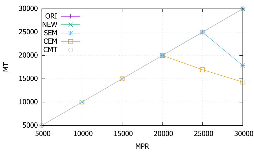
The Message Throughputs (MT) of the various configurations is plotted against different Message Publish Rates (MPR) in Fig. 6, with one plot for each of the three scenarios.
Fig. 6(a) shows the results for Scenario 1, which involves only one broker. This scenario highlights the relative performance of the various configurations in the absence of interconnected brokers. Not only did the original Mosquitto implementation (ORI) achieve the idealized Message Throughput (CMT), the extended Mosquitto implementation (NEW) can do the same when no execution monitor is installed. This means that when the security mechanisms are inactive, the performance impact of the added software infrastructure is negligible.
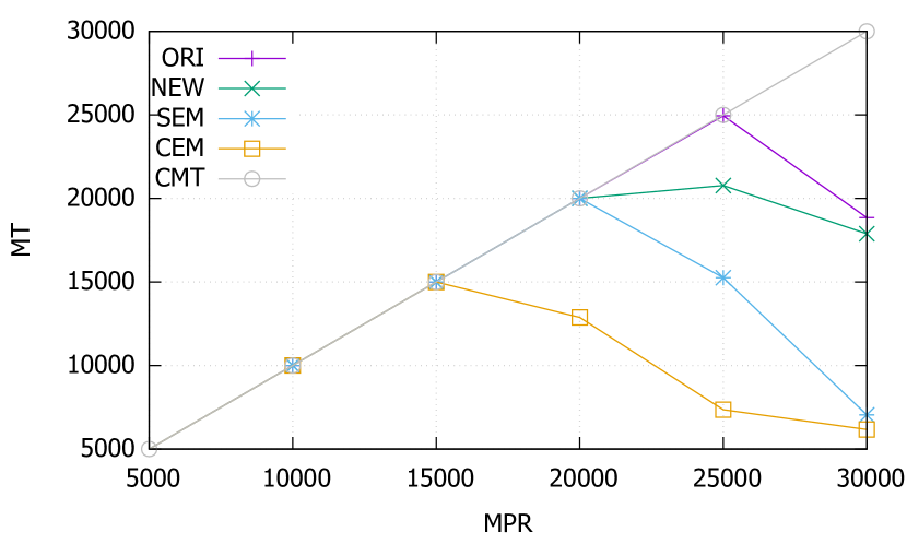
In Fig. 6(a), we also notice that when edit automata are installed, the Message Throughput began to drop after the Message Publish Rate reached a certain point. This is when the broker was overwhelmed, and started to drop messages. The best achieved Message Throughput prior to message dropping signifies the capacity of the configuration in question: 25K mps for SEM, and 20K mps for CEM. This means that as the edit automaton does more work, the best achieved Message Throughput degrades. This pattern persists in Scenario 2 and 3 (Fig. 6(b) and 6(c)).
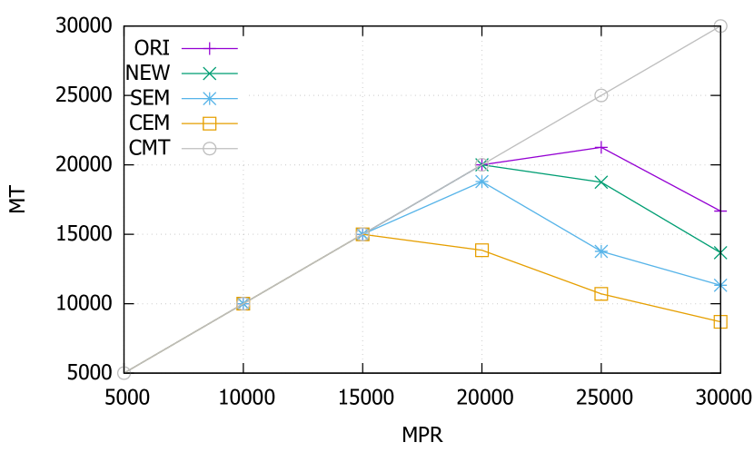
Fig. 6(b) and 6(c) show the impact of multiple brokers and brokering policies. Now even the ORI and NEW configurations failed to match the idealized Message Throughput (CMT). As expected, the more brokers are involved, the higher the latency, and the best achieved Message Throughput will decline. Scenario 3 introduces the most latency of the three scenarios, as five interconnected brokers were involved. In that case, the best achieved Message Throughput of CEM was 15K mps.
To put our results into perspective, consider the throughput limits of the IoT cloud services offered by Amazon and Microsoft.
-
Amazon established a limit of 9K publish requests per AWS account for their AWS Services (Table Message Broker Limits in the website) (awslimits, ). This means that each AWS account can publish a maximum of 9K mps to their Message Broker.
-
Microsoft divides their IoT Hubs solutions into three tiers: S1, S2 and S3 (microsoftlimits, ). Tier S3 is the most powerful of them, allowing an average message throughput of 208,333 messages per minute (i.e., approximately 3.5K mps).
Comparing these values against best achieved Message Throughput of 15K mps achieved by CEM (the configuration with the slowest execution monitor among the five) in Scenario 3 (the scenario with the highest latency among the three), our proposed protection scheme appears to have no trouble coping with the throughput requirements expected in commercial IoT frameworks.
Additional experiments are reported in (Thesis, , §5.3.4). These experiments study how Message Throughput is impacted by edit automata that either suppress or inject messages.
9. Conclusion and Future Work
In this work, we have demonstrated the utility and performance of three protection mechanisms for event-based systems: multiple brokers, brokering policies, and execution monitors. A number of research directions are listed here. (1) We would like to be able to specify the overall collaboration protocol of an ensemble of devices, and then compile the specification to low-level brokering policies and edit automata for enforcement. This relieves the user from having to write error-prone scripts, as is now practised in many commercial IoT frameworks. (2) Exactly what family of security policies are enforceable (Schneider:2000, ; EA:IJIS, ; EA:TISSEC, ; Fong:2004, ) by the combination of multiple brokers, brokering policies, and execution monitors? We believe that the answer to this question depends on the relative network speed assumed in the formal operational semantics. (3) Using brokers as protection domains (§6.2.3) allows us to impose access control over the senders and receivers of messages. Yet one may want to also restrict the contents of the messages being sent. How content-based access control can be imposed on messages passing through network links in a manner efficient enough to meet the throughput demand of IoT applications is a technical challenge.
References
- [1] Aws service limits. http://docs.aws.amazon.com/general/latest/gr/aws_service_limits.html. [Online; accessed 2017-10-30].
- [2] Mqtt sernsor. https://home-assistant.io/components/sensor.mqtt/. [Online; accessed 2017-12-04].
- [3] Scale your iot hub solution. https://docs.microsoft.com/en-us/azure/iot-hub/iot-hub-scaling. [Online; accessed 2017-10-30].
- [4] Mzbench. https://github.com/machinezone/mzbench, 2017.
- [5] vmq_mzbench. https://github.com/erlio/vmq_mzbench, 2017.
- [6] Asma Alshehri and Ravi Sandhu. Access control models for cloud-enabled internet of things: A proposed architecture and research agenda. In Proceedings of the IEEE 2nd Conference on Collaboration and Internet Computing, pages 530–538, Pittsburgh, PA, USA, November 2016.
- [7] Asma Alshehri and Ravi Sandhu. Access control models for virtual object communication in cloud-enabled iot. In Proceedings of the 2017 IEEE Conference on Information Reuse and Integration, pages 16–25, San Diego, CA, USA, August 2017.
- [8] Zoran B Babovic, Jelica Protic, and Veljko Milutinovic. Web performance evaluation for internet of things applications. IEEE Access, 4:6974–6992, 2016.
- [9] Andrew Banks and Rahul Gupta. MQTT Version 3.1.1. OASIS standard, 2014.
- [10] András Belokosztolszki, David M Eyers, Peter R Pietzuch, Jean Bacon, and Ken Moody. Role-based access control for publish/subscribe middleware architectures. In Proceedings of the 2nd international workshop on Distributed event-based systems, pages 1–8. ACM, 2003.
- [11] Frank Buschmann, Regine Meunier, Hans Rohnert, Peter Sommerlad, and Michael Stal. Pattern-Oriented Software Architecture, volume 1. Wiley, 8 1996.
- [12] Pietro Colombo and Elena Ferrari. Access control enforcement within MQTT-based internet of things ecosystems. In Proceedings of the 23rd ACM Symposium on Access Control Models and Technologies (SACMAT’2018), Indianapolis, IN, USA, June 2018.
- [13] Thomas H. Cormen, Charles E. Leiserson, and Ronald L. Rivest. Introduction to Algorithms. MIT Press, 1989.
- [14] Tam Thanh Doan, Reihaneh Safavi-Naini, Shuai Li, Sepideh Avizheh, Muni Venkateswarlu Kumaramangalam, and Philip W. L. Fong. Towards a resilient smart home. In Proceedings of the 2018 Workshop on IoT Security and Privacy (IoT S&P’2018), pages 15–21, Budapest, Hungary, August 2018.
- [15] Eclipse. Mosquitto. http://mosquitto.org.
- [16] D. Evans and A. Twyman. Flexible policy-directed code safety. In In Proceedings of the 1999 IEEE Symposium on Security and Privacy (S&P’1999), page 32–45, Oakland, California, May 1999.
- [17] M. Felleisen, R. B. Findler, and M. Flatt. Semantics Engineering with PLT Redex. MIT Press, 2009.
- [18] Ludger Fiege, Mira Mezini, Gero Mühl, and Alejandro P. Buchmann. Engineering event-based systems with scopes. In Proceedings of the 16th European Conference on Object-Oriented Programming (ECOOP’02), volume 2374 of LNCS, pages 309–333, Málaga, Spain, June 2002.
- [19] Ludger Fiege, Gero Mühl, and Felix C. Gärtner. A modular approach to build structured event-based systems. pages 385–392, Madrid, Spain, March 2002.
- [20] Ludger Fiege, Gero Mühl, and Felix C. Gärtner. Modular event-based systems. The Knowledge Engineering Review, 17(4):359–388, December 2002.
- [21] Philip W. L. Fong. Access control by tracking shallow execution history. In Proceedings of the 2004 IEEE Symposium on Security and Privacy, pages 43–55, Berkeley, CA, USA, May 2004.
- [22] Juan Carlos Fuentes Carranza. Scoping and execution monitoring for IoT middleware. Master’s thesis, University of Calgary, 2018. http://hdl.handle.net/1880/106346.
- [23] Alban Gabillon and Emmanuel Bruno. Regulating IoT messages. In Proceedings of the International Conference on Information Security Practice and Experience (ISPEC’2018), volume 11125 of LNCS, pages 468–480, Tokyo, Japan, September 2018.
- [24] Carl A Gutwin, Michael Lippold, and TC Graham. Real-time groupware in the browser: testing the performance of web-based networking. In Proceedings of the ACM 2011 conference on Computer supported cooperative work, pages 167–176, 2011.
- [25] Vincent C. Hu, David Ferraiolo, Rick Kuhn, Adam Schnitzer, Kenneth Sandlin, Robert Miller, and Karen Scarfone. Guide to attribute based access control (ABAC) definition and considerations. NIST Special Publication 800-162, NIST, 2014.
- [26] K. Krukow, M. Nielsen, and V. Sassone. A logical framework for history-based access control and reputation systems. Journal of Computer Security, 16(1):63–101, 2008.
- [27] Leonard J. LaPadula and D. Elliott Bell. MITRE technical report 2547, volume II. Journal of Computer Security, 4:239–263, 1996.
- [28] Jay Ligatti, Lujo Bauer, and David Walker. Edit automata: Enforcement mechanisms for run-time security policies. International Journal of Information Security, 4(1-2):2–16, 2005.
- [29] Jay Ligatti, Lujo Bauer, and David Walker. Run-time enforcement of nonsafety policies. ACM Transactions on Information and System Security (TISSEC), 12(3):19, 2009.
- [30] Roger A Light. Mosquitto: server and client implementation of the MQTT protocol. The Journal of Open Source Software, 2(13), may 2017.
- [31] Gero Mühl, Ludger Fiege, and Peter R. Pietzuch. Distributed Event-Based Systems. Springer, 2006.
- [32] Phu H. Phung, Hong-Linh Truong, and Divya Teja Yasoju. P4SINC - an execution policy framework for IoT services in the edge. In Proceedings of the 2017 IEEE International Congress on Internet of Things, pages 137–142, Honolulu, HI, USA, June 2017.
- [33] Alessandra Rizzardi, Sabrina Sicari, Daniele Miorandi, and Alberto Coen-Porisini. AUPS: An open source AUthenticated Publish/Subscribe system for the Internet of Things. Information Systems, 62:29–41, 2016.
- [34] John Rushby. Noninterference, transitivity, and channel-control security policies. Technical Report CSL-92-02, Computer Science Laboratory, SRI International, Menlo Park, CA, December 1992.
- [35] Ravi S. Sandhu, Edward J. Coyne, Hal L. Feinstein, and Charles E. Youman. Role-based access control models. IEEE Computer, 29(2):38–47, 1996.
- [36] Fred B. Schneider. Enforceable security policies. ACM Transactions on Information and System Security, 3(1):30–50, February 2000.
- [37] Savio Sciancalepore, Michal Pilc, Svenja Schröder, Giuseppe Bianchi, Gennaro Boggia, Marek Pawlowski, Giuseppe Piro, Marcin Plóciennik, and Hannes Weisgrab. Attribute-based access control scheme in federated IoT platforms. In Proceedings of the International Workshop on Interoperability and Open-Source Solutions, volume 10218 of LNCS, pages 123–138, Stuttgart, Germany, November 2016.
- [38] Sabrina Sicari, Alessandra Rizzardi, Daniele Miorandi, and Alberto Coen-Porisini. Security towards the edge: Sticky policy enforcement for networked smart objects. Information Systems, 71:78–89, 2017.
- [39] Úlfar Erlingsson and F. B. Schneider. IRM enforcement of Java stack inspection. In Proceedings of the 2000 IEEE Symposium on Security and Privacy (S&P’2000), pages 246–255, Berkeley, California, May 2000.
- [40] D. S. Wallach, A. W. Appel, and E. W. Felten. SAFKASI: A security mechanism for language-based systems. ACM Transactions on Software Engineering and Methodology, 9(4):341–378, October 2000.