Non-trivial spatial dependence of the spin torques in L10 FePt-based tunnelling junctions
Abstract
We present an ab-initio study of the spin-transfer torque in a Fe/MgO/FePt/Fe magnetic tunnel junctions. We consider a FePt film with a thickness up to six unit cells, either in direct contact with the MgO spacer or with an intercalated ultra-thin Fe seed layer. We find that in the FePt layer the torque is not attenuated as strongly as in the case of pure Fe. Moreover, in FePt the torque alternates sign at the Fe and Pt atomic planes throughout the stack for all FePt thicknesses considered. Finally, when Fe is intercalated between MgO and L-FePt, the torque is sharply attenuated and it is transferred to FePt only for a Fe seed layer that is less than two-atomic-planes thick. We attribute these features to the different spatial profiles of the exchange and correlation field and the induced non-equilibrium spin accumulation. The calculated tunnelling magneto-resistance of the Fe/MgO/FePt/Fe junctions studied is enhanced with respect to the one of Fe/MgO/Fe, while it is reduced with Fe intercalation. Our work shows that L-FePt junctions can be promising candidates for current-operated magnetic devices and that the magnetic texture at the atomic scale has an important effect on the spin transfer torque.
I Introduction
Magnetic random access memories are believed to be among the most promising candidates to deliver the future of scalable, non-volatile, rapidly accessible data storage. At the heart of these devices are magnetic tunnel junctions (MTJs), which store data on the relative orientation of the magnetisation vectors of two magnetic layers separated by an insulating barrier. Reading and writing such junctions can be efficiently performed by applying an electric current through the device; exploiting the tunnelling magneto-resistance (TMR) [(1)] effect for reading and using spin-transfer torque (STT) [(2)] to write. STT arises when a current passes across two ferromagnets having different magnetisation directions and it is caused by the transfer of angular momentum between the two mediated by the current. The conduction electrons become spin polarised by passing through the first magnetic layer and their angular momentum is then transferred to the second. The ideal insulating barrier acts as a spin-filter maximising the spin-polarisation of the current and hence the torque.
Optimising the device structure to achieve low write currents is an important challenge in realising the potential of these devices. Whilst early demonstrations of MTJs focused on devices with in-plane layers magnetisation, the write current can be reduced significantly by adopting an out-of-plane geometry, where the magnetisation direction of both layers is oriented normally to the barrier interface. In junctions with this configuration, known as perpendicular MTJs (pMTJs), a large perpendicular magnetic anisotropy (PMA) is required to overcome the shape anisotropy of the thin film and enforce thermal stability in scalable devices.
State-of-the-art devices are based upon CoFeB/MgO thin films, which can reach a TMR of up to 604% at room temperature and 1144% at low temperature [(3)]. Furthermore, a large PMA has been observed at the CoFeB/MgO interface which is sufficient to achieve a perpendicular geometry in ultra-thin layers [(4)]. Alternatively, L FePt is a popular material choice for high-density magnetic recording, since it has a large magneto-crystalline PMA, , allowing stable grain sizes down to a few nanometres [(5)]. Despite the large uniaxial anisotropy, switching has been observed in FePt/Au giant magneto-resistance pillars with the aid of an applied magnetic field [(6)]. Theoretical calculations of a FePt/MgO MTJ predicts a TMR of 340% for a Fe terminated interface [(7)].
Unfortunately, growing FePt/MgO devices can be challenging since the lattice mismatch between L10 FePt and MgO is large, [(8)]. This may cause issues during the growth process, such as the inability of preserving the epitaxy across uneven layers. Strain can also cause a significant change in the magnetic properties of the FePt layer. In particular calculations have shown that a strain of 4% can reduce the PMA to about 10% of its original value [(6)]. Practically, such strain can be reduced by inserting a seed-layer with a more amenable lattice constant at the MgO/FePt interface.
In this work we investigate a series of FePt/MgO-based pMTJs in order to establish their potential for future device applications. We utilise ab-initio models to calculate the spin-transfer torque and the TMR for a range of FePt-based MTJ structures. We begin by detailing our computational method, before presenting results on the atom-resolved STT in the zero-bias limit for an Fe/MgO/Fe junction. This has an electronic structure analogous to that of CoFeB-based MTJs and hence provides a useful starting point for the discussion. We then continue with the analysis of the torque acting on the MTJs with FePt/Fe free layers and with a thin Fe seed layer intercalated at the MgO interface. In this case we vary the thickness of both the FePt layer and the seed layer (including the case where there is no seed layer). We find that a MgO/FePt interface yields a STT that decays more slowly in the free layer than in the MgO/Fe case, while the insertion of a Fe seed layer produces results similar to the FePt-free case. We then present the outcome of our TMR calculations and the STT acting on the Fe reference layer for some representative cases. Finally we replace the Fe atoms in the seed layer with Ni. This provides a comparison and helps us to formulate an argument about the origin of the spatial dependence of the STT.
II Computational Method
Our approach for calculating the spin-transfer torque follows the prescription provided by Haney et al. in reference [(9)] and is based on isolating the transport (non-equilibrium) contribution to the density matrix from the equilibrium part. The influence that an electric current has on the system can be estimated from first principles by combining density functional theory and the non-equilibrium Green’s functions method for transport (DFT+NEGF). All calculations have been performed with the Smeagol code [(10; 11; 12; 13)], which implements the DFT+NEGF scheme within the numerical atomic orbital framework of the Siesta package [(14)].
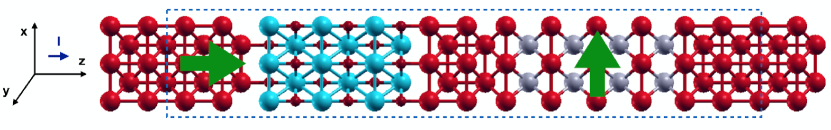
The system set up for the quantum transport calculation sandwiches the magnetic tunnel junction between two semi-infinite leads (see Fig. 1). These are assumed to be made of bulk material and at equilibrium. Note that a certain portion of the electrodes has to be included in the scattering region in order to ensure the continuity of the electrostatic potential. Here the magnetisation of the reference or fixed layer, , is considered to be magnetised along (the transport direction) and the one of the free layer, , along , so that the two form a angle. A voltage is applied in such a way that the electron flux is flowing along the stacking direction, , in our convention from the reference layer to the free one.
The component of the torque vector, , which is responsible for the switching between the parallel and the anti-parallel magnetisation configurations is the one that lies in the plane defined by and , namely the plane. In the free layer this component coincides with , which is the main focus of our study. In order to reduce the computational costs, we limit our analysis to the torque response to a small bias, the torkance, meaning that all calculations are performed in the linear response approximation. At an atom in the free layer the torkance is defined as
| (1) |
and this can be estimated with a zero-bias calculation. Here denotes the exchange and correlation field, namely the derivative of the exchange and correlation energy, , with respect to the magnetisation density, , . Thus, the derivative of with respect to voltage embodies the spin contribution due to the rearrangement of the electronic population under non-equilibrium conditions. Henceforth this will be referred to as the non-equilibrium spin density or the spin accumulation. As such, the torque is the result of the interaction between the internal static field and the non-equilibrium spin density generated by the current flow. Further details on the calculation of the spin-transfer torque and the torkance can be found in Refs. [(15; 16)].
A series of junctions are constructed, all having a barrier of 6 MgO layers sandwiched between two semi-infinite leads of bulk bcc Fe oriented along the (001) direction. Periodic boundary conditions are applied in the plane perpendicular to the transport, as a result of the perfect epitaxy of the junction. The in-plane lattice constant is taken to be throughout the system. The out-of-plane lattice constants of the remaining materials were chosen according to information provided in reference [(17; 8)], in particular , . The same studies assess that the most stable interfacial configuration is made of a Fe-terminated FePt surface on top of O (Fe) for the FePt/ MgO (FePt/Fe) interface, with an inter-plane distance of (). The accuracy of such estimates was found satisfactory by relaxation of the different structures. The local spin density approximation (LSDA) for the exchange correlation potential was adopted. A real-space mesh cut-off of Ry along with a 1515 -point mesh in the plane orthogonal to transport were found to yield converged results. We adopted double polarised orbitals for each atomic species and the convergence of the radial cut-offs was verified by comparing the band structure of bulk materials with the result of all-electron calculations. Since the introduction of spin-orbit coupling effects did not yield a sizeable change to our calculated torques we have omitted relativistic corrections.
III Results
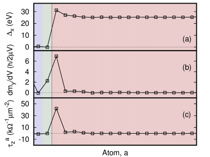
We begin by examining the properties of a Fe/MgO/Fe MTJ to later discuss their modification upon the introduction of a FePt layer. As shown in Eq. (1), the torkance is given by the vector product of the exchange and correlation field and the non-equilibrium spin density. Since the free layer is magnetised in the -direction and within the LSDA the exchange and correlation field is proportional and locally parallel to the magnetisation, the only relevant components to the torkance are and . These two components and the resulting torkance, , are shown in Fig. 2.
In general, peaks at the Fe/MgO interface and then presents small oscillations with the period of the interlayer Fe separation, . Such profile does correlate with the real space profile of the equilibrium magnetic moment (not displayed), which is also enhanced at the Fe/MgO interface. In contrast, the non-equilibrium spin density [panel (b)] has an appreciable magnitude only in the region around the Fe/MgO interface. This decays in the Fe layer and is almost fully attenuated a few monolayers from the interface. Such behaviour will later be compared with that in FePt and in Ni. Finally note that there is an appreciable non-equilibrium spin density also in the MgO, although it does not contribute to the torkance since the exchange and correlation field vanishes in absence of a local magnetization [see panel (a)].
If we now consider the torkance we note that this is sharply peaked at the Fe/MgO interface and is attenuated in the Fe layer at the same speed of the non-equilibrium spin density. In fact, for this Fe/MgO/Fe case the spatial dependance of the torkance resembles closely that of the spin accumulation, given the fact that the exchange and correlation field has little spatial dependence in Fe. Let us remark, however, that the point-by-point vector product of the quantities in panels (a) and (b) does not give the torkance in panel (c), since the sum of the products of the matrix elements does not equal the product of the sums [namely, - see formula (1)].
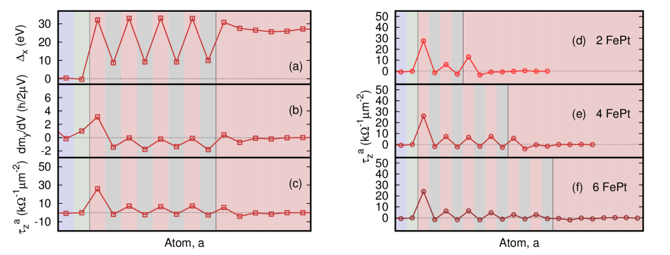
We now explore the effects of inserting a layer of FePt at the MgO/free layer interface. Figures 3(a)-(c) show, as with the case of the Fe/MgO/Fe MTJ, the relevant components of and contributing to the total torkance along for a FePt layer 4-unit-cell thick. From panel (a) it is clear that the exchange and correlation field is enhanced at the Fe sites, and also finite at the Pt ones. This is because in L FePt there is an induced magnetic moment on the Pt ions (this is about as calculated from the Mülliken population analysis), in agreement with previous ab-inito calculations [(8)]. The oscillations in the profile remain constant in the FePt layer without any sign of decay, and then in the Fe layer the profile returns to resemble the one observed before in Fig. 2. Note that is an equilibrium property, which essentially depends on the presence of an exchange splitting in a given material. As such one does not expect a decay of unless there is a decay in the magnetisation.
In contrast to the pure Fe case, the non-equilibrium spin density has lower intensity in FePt than in Fe but a significantly less attenuated decay [panel (b)]. The total non-equilibrium spin density shows regular oscillations within the FePt layer, whilst it is enhanced at both the FePt/Fe and the MgO/FePt interfaces, and then vanishes within a few unit cells of the Fe lead. Furthermore we observe that in Pt has opposite sign with respect to that of the first Fe layer in contact to MgO. Finally, the torkance [panel (c)] is again peaked at the interface with MgO but its strength is reduced in comparison to that computed for the Fe/MgO/Fe MTJ with the same MgO thickness. Within the FePt layer the torkance does not attenuate as in Fe but persists to reach the Fe-only side of the free layer. Most interestingly the torkance has an oscillatory behaviour in FePt, presenting small negative values at the Pt layers and positive at the Fe ones. Such oscillations are common in antiferromagnets [(15)] and here are observed also in a ferromagnet with non-trivial magnetic texture. It is also interesting to note that, despite the larger spin accumulation at Pt sites, the resulting torque is smaller than that at the Fe ones. This is due to the fact that the exchange and correlation field in Pt is significant weaker than in Fe (because the magnetisation is smaller).
The persistence of the torkance in the FePt layer remains as we change the FePt thickness, (number of unit cells). This can be seen in the panels (d)-(f) of Fig. 3. For a thin layer [panel (d)] the torque is enhanced at the FePt/Fe interface, while it is attenuated for all the other cases [e.g. see in panel (f)]. Furthermore, for all the thicknesses considered the torkance remains strikingly positive at all the Fe atomic planes of FePt, while it is small and negative at the Pt ones. Moreover, the intensity of the peak at the MgO/FePt is not modified by the increase in thickness.
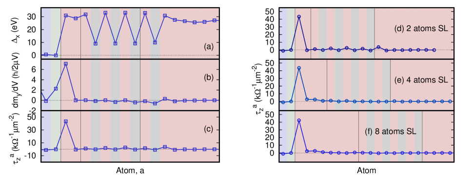
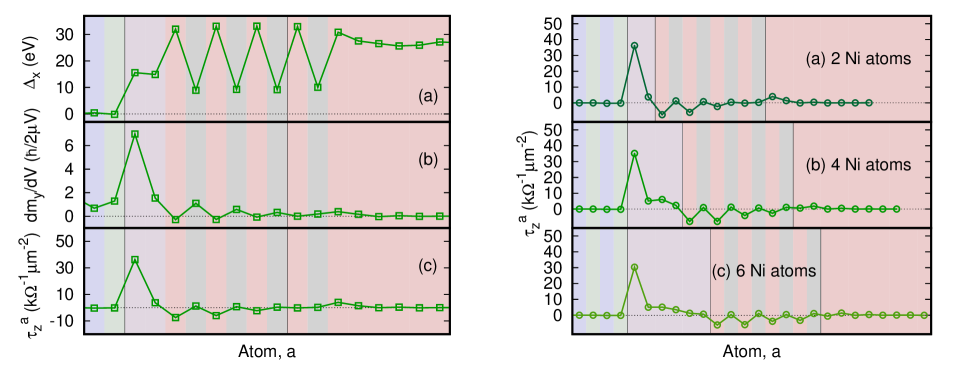
Although Fe/MgO/FePt/Fe junctions provide an interesting case of study, the significant lattice mismatch between MgO and L10 FePt ( 8.5%) makes their experimental realisation troublesome. This problem may be overcome by inserting a compatible seed layer at the MgO/FePt interface. Hence, we have analysed the influence of incorporating a thin Fe seed layer (SL) between the MgO and the FePt, keeping the thickness of the FePt layer constant at 4 unit cells. The Fe SL has different effects depending on its thickness (see Fig. 4). We notice from panel (a) that the exchange and correlation field profile in FePt is analogous to the previous case (since the equilibrium magnetisation profile is also unchanged), while is almost constant in the seed layer. The non-equilibrium spin density still oscillates in FePt, although the amplitude of such oscillations is much smaller than that obtained in absence of the SL. Consequently, the torkance [panel (c)] is peaked at the MgO/Fe interface with the SL and its intensity is comparable to that observed for the Fe/MgO/Fe case (see figure 3). The torkance, however, is not exactly zero away from the SL, in particular on the Fe atoms of FePt and at the FePt/Fe interface. This does not happen for thicker Fe SLs [panels (e) and (f)], for which the total torkance decays before reaching the interface with FePt. In general, however, the main effect of the seed layer is to suppress the persistence of the torkance in FePt, so that all the angular momentum transfer takes place in the seed layer.
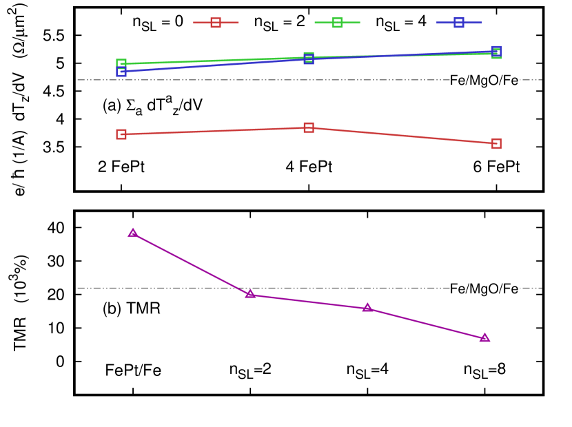
We now move to analyse the total torkance and the TMR of each junction. Figure 5(a) shows the total torkance integrated over the free layer, , for different thicknesses of the FePt layer. We present results for the situation where there is no SL (red squares), and for a Fe SL of respectively 2 (green squares) and 4 atomic planes (blue squares). For each SL thickness, the torkance shows little dependence on the thickness of the FePt layer. When there is no SL this is attributed to the oscillatory behaviour without attenuation of the torkance profile as observed in Fig. 3. In contrast, when a SL is present most of the torque resides at the first MgO/Fe interface so that the thickness of the FePt becomes irrelevant (see Fig. 4). Interestingly, when a SL is present the total torkance transferred into the Fe/MgO/Fe/FePt MTJ is larger than that of a simpler Fe/MgO/Fe MTJ with identical barrier (dashed black line). This is no longer true when the SL is absent. Such finding means that the introduction of a Fe seed layer not only helps in achieving a better epitaxy during the growth but also facilitates a larger spin transfer torque.
Figure 5(b) shows the calculated TMR for each junction (in all cases the FePt layer comprises 4 layers) and a comparison with that of a Fe/MgO/Fe MTJ with an identical barrier. We observe that the junction with no Fe SL presents the largest TMR, despite having the lowest torkance. This is unexpected, since in FePt bands with symmetry, namely those with the largest transmission across MgO, are present for both spin channels [(7)]. Such feature returns a predicted TMR for MTJs with FePt leads not exceeding 340% [(7)]. However, here the situation is different since in all our MTJs the leads are made of Fe, so that spin filtering is always in place. As such, in our case the addition of a FePt layer (or a complex Fe/FePt layer) changes the details of the spin-dependent scattering potential, but does not alter the main spin-filtering mechanism at play in Fe/MgO/Fe junctions. Interestingly, as the thickness of the Fe SL gets larger, the value of the TMR is reduced.
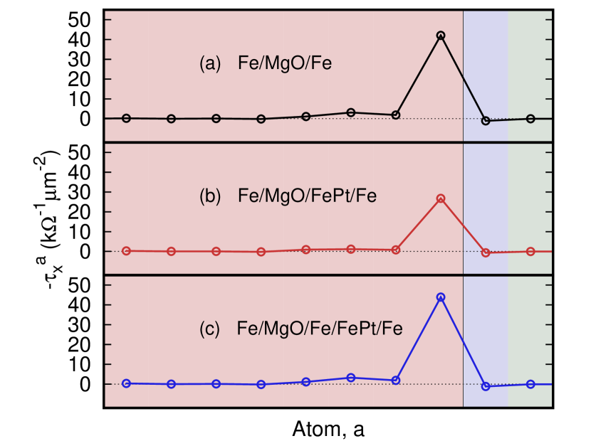
So far the left electrode has been considered to be the fixed layer, namely the one producing the spin-polarised current. It is now interesting to look at the opposite case, namely the one where the electrons flux flows from the right-hand side to the left-hand side electrode. This is the situation where the FePt/Fe composite electrode acts as the fixed, current polarising, layer. Since in the right electrode the magnetisation is along the direction, the relevant torque in this case is . This is presented in Fig. 6 for three representative junctions: (a) Fe/MgO/Fe, (b) Fe/MgO/FePt(4)/Fe, and (c) Fe/MgO/Fe(2)/FePt(4)/Fe, where the numbers in parentheses indicate the number of unit cells. Since in this geometry the current flows in the opposite direction than previously, we have plotted , namely the torque component that will lead to an alignment of the magnetisations of the fixed and free layers. The trend of is in all cases analogous to that of for the Fe/MgO/Fe MTJ [see Fig. 2 (c)], namely the STT is peaked at the magnet/insulator interface and is negligible elsewhere. The only significant difference between the three MTJs is the reduction of approximately a factor two of the peak intensity for the Fe/MgO/FePt(4)/Fe stack [panel (b)].
IV Discussion
The results presented so far indicate that the STT (the torkance) varies strongly with the distance from the MgO interface, and that the details depend subtly on the specific layer structure. In general, Fe seems capable of absorbing a significant amount of angular momentum, so that only a few Fe monolayers are enough to make the STT decay sharply from the MgO interface. The main cause of such effect has to be found in the intense Fe exchange field. In fact, the strong exchange interaction in Fe relaxes the non-equilibrium spin density (the spin accumulation) toward the local direction of the magnetisation within a few atomic layers from the interface, so that there is little away from the interface itself. In addition the exchange and correlation field remains almost constant within the Fe layer, resulting in a torque that persists little away from the interface with MgO.
In L FePt the alternating planes of Fe and Pt lead to a magnetisation texture that is non-uniform at the atomic scale. In particular is small at the Pt sites so that the average exchange and correlation field is reduced with respect to that of the pure Fe case. As a consequence the spin accumulation can penetrate longer into the free layer so that the STT decays less sharply. In order to further investigate the effects of the exchange field on the spatial decay of the torque we now consider a Ni seed layer since it has a much smaller moment, and thus exchange field, than Fe. The calculation has been simplified by maintaining the bcc structure and the lattice constant of Fe. As such our device stack does not correspond to a likely experimental situation but just serves the purpose of comparing the different seed layers. The atomic resolved torkance for a Fe/MgO/Ni/FePt/Fe stack with a Ni seed layer comprising 2, 4 and 6 atomic planes is shown in figure 7.
As in the case of a Fe seed layer, the torque [panel (c)] is strongly peaked at the Ni/MgO interface, but now it does not decay entirely and thus a non-vanishing STT with an oscillatory behaviour persists into the FePt layer. A closer look at the profile of across the junction [panel (a)] reveals that the exchange and correlation field in Ni is about half of that of Fe [see Figure 4(a)]. As a consequence, in Ni the spin accumulation does not relax along the local direction of the magnetization as efficiently as in Fe, a fact that can be appreciated by comparing Fig. 7(b) with Fig. 4(b). Interestingly, the attenuation of the spin accumulation and thus of the torque is not complete even for relatively thick Ni seed layers, as can be seen in panels (d) through (f). A second interesting observation concerns the phase of the oscillations of the STT in the FePt layer. In fact for a junction where FePt is in direct contact with the MgO barrier, the torque is positive at the Fe planes and negative (although rather small) at the Pt ones. The same behaviour, although with a much reduced torque is observed for Fe intercalation (in the presence of a Fe seed layer). In contrast when the seed layer is made of Ni the sign of the STT on the FePt layer changes, becoming negative at the Fe planes and positive (although small) at the Pt ones. As a result the total integrated torque over the entire free layer (seed layer plus FePt) for Ni intercalation is two thirds than that obtained with Fe intercalation.
Finally, we wish to make a few general remarks on the spatial dependence of the STT. Macroscopic models combining the Landau-Lifshitz-Gilbert equation for the magnetisation dynamics with a diffusion model for the spin accumulation [(18; 19)] suggest that the spin accumulation is maximised in regions where there is a large magnetisation gradient, namely at interfaces. This is confirmed here at the microscopic level. In all cases investigated we find the maximum spin accumulation, and hence torque, at the interface between the free layer and MgO regardless of the presence of a seed layer. Furthermore, we also find an enhanced spin accumulation and torque at the second interface between the free layer and the Fe lead, although this is small since the spin accumulation always decays in the free layer. The fine details of the spin accumulation profile depend on how the entire stack responds to the application of an external bias. This in turn is affected by the reorganisation in the occupation of the states around the Fermi surface, which is indeed a subtle effect.
In general a large exchange splitting causes the spin accumulation to relax faster along the local magnetisation direction. As such we expect the spin accumulation to decay more severely in the free layer of stacks where there is a large torque at the first few atomic layers in contact with the MgO barrier. This in turn depends on the strength of the exchange and correlation field, which in the LSDA can be written as
| (2) |
where is the local magnetisation vector, , is the LSDA exchange and correlation energy, is the exchange and correlation energy density of the homogeneous electron gas, is the charge density and the Bohr magneton. Crucially the LSDA is locally parallel to the magnetisation direction. As such one expects (and hence the torque) to change sign as the local magnetisation changes sign (as in the case of antiferromagnets). Furthermore one can show that , where is the Stoner parameter [(20)]. This means that for similar Stoner coupling the exchange and correlation field is more intense for materials presenting larger magnetization. This last feature explains the difference in and torque between the Fe and the Ni seed layer. In fact Fe and Ni have rather similar Stoner parameter but their magnetization differ by more than a factor three.
V Conclusions
In conclusion, we have calculated the STT acting upon the free ferromagnetic layer in a series of FePt-based magnetic tunnel junctions. For a simple Fe/MgO/Fe MTJ the torkance is peaked at the MgO interface and decays within 4 atomic planes. When the stack is modified to include FePt [Fe/MgO/FePt/Fe] the torkance decays much slower and persists into the free layer up to at least 12 atomic planes. Such retention is associated to torkance oscillations at the length scale of the Fe-Pt plane separation. Since the lattice mismatch between MgO and FePt is large we have explored the option to intercalate a Fe seed layer at the interface between MgO and FePt. Also in this case the torkance is significant only at the first MgO/Fe interface and it vanishes in FePt. This is the result of the strong reduction of the spin accumulation beyond the Fe seed layer. Such strong attenuation appears to originate from the large exchange and correlation field in Fe, which rapidly aligns the spin accumulation along the local direction of magnetization. Such hypothesis is confirmed by calculations for the STT in some hypothetical MTJs incorporating a Ni seed layer. Since Ni has an exchange and correlation field that is weaker than that of Fe, it is less effective at suppressing the spin accumulation (in absorbing angular momentum) and thus the attenuation of the torkance is weaker. All together our results suggest that the atomic and materials details of the MTJs stack play an important role in determining the total STT that a free layer can experience. This knowledge can help in designing stacks with maximal torkance, so that a reduction in the critical current for switching can be achieved.
VI Acknowledgements
This work has been supported by the Science Foundation Ireland Principal Investigator award (grant no. 14/IA/2624 and 16/US-C2C/3287) and TCHPC (Research IT, Trinity College Dublin). The authors wish to acknowledge the DJEI/DES/SFI/HEA Irish Centre for High-End Computing (ICHEC) for the provision of computational facilities and support.
References
- (1) M. Julliere, Phys. Lett. A 54, 225 (1975).
- (2) J. Slonczewski, J. Magn. Magn. Mater. 159, L1 (1996).
- (3) S. Ikeda, K. Miura, H. Yamamoto, K. Mizunuma, H.D. Gan, M. Endo, S. Kanai, J. Hayakawa, F. Matsukura and H. Ohno, Nature Materials 9, 721 (2010).
- (4) D.C. Worledge, G. Hu, D.W. Abraham, J.Z. Sun, P.L. Trouilloud, J. Nowak, S. Brown, M.C. Gaidis, E.J. O’Sullivan and R.P. Robertazzi, Appl. Phys. Lett. 98, 022501 (2011).
- (5) D. Weller, A. Moser, L. Folks, and M. Best, IEEE Trans. Magn. 36, 10 (2000).
- (6) T. Seki, S. Mitani, K. Yakushiji and K. Takanashi, Appl. Phys. Lett. 88, 172504 (2006).
- (7) Y. Taniguchi, Y. Miura, K. Abe and M. Shirai, IEEE Trans. Magn. 44, 2585 (2008).
- (8) R. Cuadrado and R.W. Chantrell, Phys. Rev. B 89, 094407 (2014).
- (9) P.M. Haney, D. Waldron, R.A. Duine, A.S. Núñez, H. Guo and A.H. MacDonald, Phys. Rev. B 76, 024404 (2007).
- (10) A.R. Rocha, V.M. García-Suárez, S.W. Bailey, C.J. Lambert, J. Ferrer and S. Sanvito, Nature Materials 4, 335 (2005).
- (11) A.R. Rocha, V.M. García-Suárez, S.W. Bailey, C.J. Lambert, J. Ferrer and S. Sanvito, Phys. Rev. B 73, 085414 (2006).
- (12) I. Rungger and S. Sanvito, Phys. Rev. B 78, 035407 (2008).
- (13) I. Rungger, O. Mryasov and S. Sanvito, Phys. Rev. B 79, 094414 (2009).
- (14) J.M. Soler, E. Artacho, J.D. Gale, A. García, J. Junquera, P. Ordejòn, and D. Sànchez-Portal, J. Phys.: Condens. Matter 14, 2745 (2002).
- (15) M. Stamenova, R. Mohebbi, J. Seyedyazdi, I. Rungger and S. Sanvito, Phys. Rev. B 95, 060403 (2017).
- (16) M.O.A. Ellis, M. Stamenova and S. Sanvito, Phys. Rev. B 96, 224410 (2017).
- (17) A. Kohn, N. Tal, A. Elkayam, A. Kovacs, D. Li, S. Wang, S. Ghannadzadeh, T. Hesjedal and R.C.C. Ward, Appl. Phys. Lett. 102, 062403 (2013).
- (18) C. Abert, M. Ruggeri, F. Bruckner, C. Vogler, G. Hrkac, D. Praetorius and D. Suess, Scientific Reports 5, 14855 (2015).
- (19) C.J. García-Cervera and X.-P. Wang, J. Comput. Phys. 224, 699 (2006).
- (20) J. Simoni, M. Stamenova and S. Sanvito, Phys. Rev. B 96, 054411 (2017).