Early Routability Assessment in VLSI Floorplans: A Generalized Routing Model
Abstract.
Multiple design iterations are inevitable in nanometer Integrated Circuit (IC) design flow until desired printability and performance metrics are achieved. This starts with placement optimization aimed at improving routability, wirelength, congestion and timing in the design. Contrarily, no such practice exists on a floorplanned layout, during the early stage of the design flow. Recently, STAIRoute (Kar et al., 2013) aimed to address that by identifying the shortest routing path of a net through a set of routing regions in the floorplan in multiple metal layers. Since the blocks in hierarchical ASIC/SoC designs do not use all the permissible routing layers for the internal routing corresponding to standard cell connectivity, the proposed STAIRoute framework is not an effective for early global routability assessment. This leads to improper utilization of routing area, specifically in higher routing layers with fewer routing blockages, as the lack of placement of standard cells does not facilitates any routing of their interconnections.
This paper presents a generalized model for early global routability assessment, HGR, by utilizing the free regions over the blocks beyond certain metal layers. The proposed (hybrid) routing model comprises of (a) the junction graph model in STAIRoute routing through the block boundary regions in lower routing layers, and (ii) the grid graph model for routing in higher layers over the free regions of the blocks.
Experiment with the latest floorplanning benchmarks exhibit an average reduction of , and in netlength, via count, and congestion respectively when HGR is used over STAIRoute. Further, we conducted another experiment on an industrial design flow targeted for process, and the results are encouraging with X runtime boost when early global routing is used in conjunction with the existing physical design flow.
1. Introduction
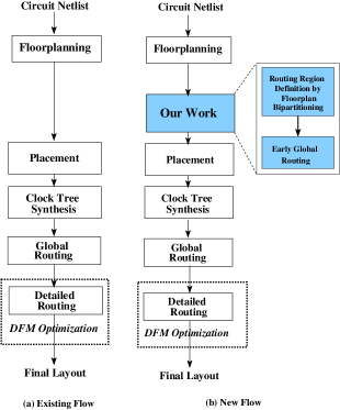
Integrated circuit (IC) design for very deep submicron (VDSM) fabrication processes requires multiple iterations, mainly during placement and global/detailed routing or even during post-routing optimization, in order to minimize the routing violations due to several lithographic issues as well as failure to conform to specified performance metrics such as power and speed due excessive wirelength and via count. In the existing physical design (PD) flow (Sherwani, 1995) (see Fig. 2 (a)), global routing (Cao et al., 2008; Kastner et al., 2002; Cho et al., 2009a; Pan and Chu, 2006; Roy and Markov, 2008; Sherwani, 1995; Xu et al., 2009; Liu et al., 2013a) plays a crucial role for obtaining an acceptable routing solution with minimal/no structural and functional violations. As per this design flow, global routing is traditionally performed, after the placement stage, on a set of nets that define the interconnections between a set of macros and standard cells in the design.
The global routing model identifies the shortest routing path of a net between the center of a bin to the center of another bin only, which contain the corresponding pins of the net. Hence, no local (intra-bin) routing, connecting a net pin contained in the bin with the bin center, is performed at this stage of the design flow and is pushed to detailed routing stage. This is commonly known as pin access problem (Alpert et al., 2013). Few instances of the local/intra-bin routing problem is illustrated in Fig. 1 where the dotted lines in the zoomed-in routing bins denote the missing local/intra-bin routes that were skipped during the global routing stage. This problem may have significant impact on the overall wirelength of the nets, while lack of local congestion estimation within a routing bin and the number of vias required during detailed routing can grossly impact a successful routing closure. Several errors due to design for manufacturibility (DFM) (Chen and Chang, 2009) continue to become more critical as the technology nodes gradually shrink, specially due to local routing and congestion hotspots, in addition to severely impacting the speed and power budget. In order to minimize the design iterations, several interleaved global and detailed routing methods such as (Batterywala et al., 2002; Cong et al., 2005; Xu and Chu, 2011; Chang and Lin, 2004; Zhang and Chu, 2012, 2013) have been proposed, in addition to integrated placement and global/detail routing frameworks (Viswanathan and Chu, 2005; Pan and Chu, 2006, 2007; Lin and Chu, 2014; Liu et al., 2013b) for incremental improvement of the routing solution and faster routing convergence with minimal violation of structural rules and functional specifications.

Evidently, all the global routing engines start with an initial placement solution, while iterative placement refinements are done using faster feedback from global/detailed routing engines. No such significant effort has been made for iterative floorplan refinement based on some early routability estimation on the floorplans, until recently STAIRoute (Kar et al., 2013) was proposed. This framework provides an insight into the routability of a given floorplan by obtaining an early global routing solution in terms of routing completion, routed wirelength, via count and congestion. These results can be helpful, alike the existing placement and routing framework, in facilitating iterative floorplan refinement as well as guiding the subsequent placement and routing, as per the proposed PD flow illustrated in Fig. 2 (b) (also see how this flow has been adapted to Fig. 10 in Section 3 for an industrial case study).
1.1. Early Global Routing in a Floorplan
Recently, an effort has been made in assessing early routability of a floorplanned layout by STAIRoute (Kar et al., 2013), using recursive floorplan bipartitioning (Majumder et al., 2004; Kar et al., 2012, 2014, 2015) results that identifies a set of monotone staircases in a floorplan as the routing regions. The capacity of these routing regions is obtained from the net cut information of the corresponding node in the bipartitioning hierarchy (MSC tree (Kar et al., 2012)). Shortest routing path for a net is identified through these regions assigning the net segments on multiple metal layers depending on the congestion scenario. As cited earlier, these nets were abstracted at the floorplan level and do not account for standard cell connectivity, due to nonavailability of the placement information available for these cells at the floorplanning stage. Instead, these nets define the interconnection between a set of macros (hard blocks) and soft blocks (a cluster of standard cells). In STAIRoute (Kar et al., 2013), the pin access problem was inherently addressed at the floorplan level, by suitably defining a set of pin-junction edges in the corresponding routing graph (GSRG). These edges facilitate well-defined routing paths between a pin (terminal) of a net to a T-Junction defined in the floorplan (Sur-Kolay and Bhattacharya, 1991) by the floorplan bipartitioning results.
Although STAIRoute (Kar et al., 2013) is shown to identify a multi-layer routing path of the nets in a floorplan, the corresponding paths are confined in the free regions bounded by the block boundaries only. These regions are identified as monotone staircase routing regions (Majumder et al., 2004; Kar et al., 2014). However, there exist many free routing regions over the macros or the soft blocks (a cluster of highly connected standard cells) over specific routing layers depending on their internal routing, i.e., a block can have free space over a specific routing layer where layers are used for its internal routing. Utilization of these free spaces may improve the routing performance in terms of wirelength, congestion and via count as well as design for manufacturability issues such as edge placement error (EPE) (Mitra et al., 2005). At floorplan level, not all the blocks, specially the soft blocks which are basically a cluster of standard cells based on functionality or higher degree of connectedness, come with the number of metal layers used for their respective internal routing. These internal routing for standard cell connectivity are realized traditionally during post-placement routing. Additionally, the lack of placement information of the standard cells during floorplanning leads to an abstraction of the original netlist barring the connectivity to the standard cells. This yields a subset of the original netlist that define the interconnections between a set of macro (hard) blocks and a set of soft blocks only. Moreover, the nets abstracted at the floorplan level are basically much larger nets if all nets are considered that that connect to both macros (including IO pads) and standard cells, as compared to the nets that connect to only the standard cells. Typically the standard cell only nets and also segments of the nets that connect standard cells and macros are masked by the soft blocks. In any case, the early global routing framework always deal with relatively larger nets using multiple routing layers. Therefore, it is reasonable to realize these early methods for assessing the routability of a floorplan which subsequently guides the placement optimization. Intuitively, this early routing results will help in faster convergence of timing driven placement optimization and subsequent global/detailed routing. We see some relevant results of industrial case study presented in Section 3.
In STAIRoute (Kar et al., 2013), all the blocks are treated as a set of routing blockages present in all available metal layers. Hence, the routing path of a net is restricted in the monotone staircase regions only, which are located in the adjoining boundary regions of the macros and soft blocks. This routing method uses specified routing layers depending on the vertical/horizontal orientation of the segments in these routing regions. Intuitively, this routing method can be effective when there are fewer number of nets at the floorplan abstraction level interconnecting the macros and soft blocks only, as compared to the original flat netlist seen at the top level that define the connectivity between the macros and standard cells. In practical designs, a macro block usually occupies some, if not all, of the permissible metal layers for routing the nets internal to it; starting from layer up to a layer say below the maximum permissible metal layer . Therefore, the routing layers {} in the regions over the planar boundary of these macros are blocked for routing the nets, while {} layers may be available using horizontal/vertical routing segments. This is also applicable to a soft block due to the routing of its internal nets, apparently blocking a number of metal layers say {} (). As cited earlier, floorplan level prior intra-block routing in any soft block is not done due to the lack of placement information of the standard cells in it. Therefore, no over-the-block routing is permitted over the soft blocks in these layers. With the increased design complexity, a large number of nets using the same number of routing layers needs to be routed with minimal wirelength and via count during early global routing in a floorplan, over-the-block early global routing of the nets in a floorplan becomes a necessity.
1.2. Major Contributions of this work
In this paper, we present a new early global routing framework called HGR in order to realize early global routing of a set of nets in a given floorplan, facilitating over-the-block routing of the (sub)nets in the upper metal layers and the routing through monotone staircase routing regions are done in lower layers. As discussed earlier, the internal routing within each block reserve up to a particular routing layer say , while HGR utilizes the free space between the boundary regions of the blocks up to and over the blocks above by proposing a novel hybrid routing graph. In this graph, the lower layers use the floorplan bipartitioning results, while the upper layers use a modification of the existing grid graph model adapted for floorplans. Like in STAIRoute, this routing model aims to address the pin-access (local/intra-bin) problem by suitably defining a set of relevant edges in this graph. Here, will define the maximum layer already used by all the macros for their internal routing, while the soft blocks will reserve the metal layers up to for their internal routing to be done after the traditional placement of the standard cells is done by the existing design flow (refer to Fig. 2 (b)). Therefore, the routing of the nets internal to the soft blocks defining the interconnection of the standard cells is beyond the scope of this work.
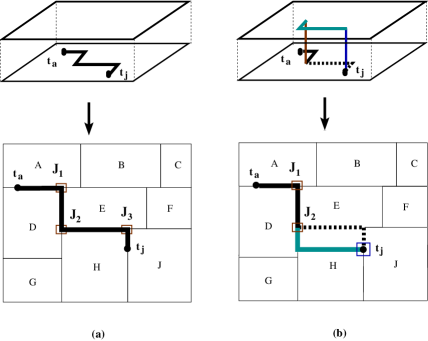
A comparative example presented in Fig. 3 gives an idea of the proposed work against STAIRoute. This example shows that, in all layers, STAIRoute confines the nets through the staircase routing regions only, while HGR can use both the staircases as well as the free regions above the blocks. It can be noted that if layer and above are uniformly free for routing over all the blocks, the staircase regions prevalent up to cease to exist. In this regard, the grid graph model becomes relevant and hence used in our hybrid routing model.
We organize the rest of this paper as follows: the proposed early global routing approach HGR in the floorplans is described in Section 2 for over-the-block routing in a floorplan and also explores the scope of exploring an early abstraction of EPE into the routing penalty for obtaining an EPE-aware early routability assessment method. Experimental results and relevant discussions appear in Section 3, along with concluding remarks in Section 4.
2. This work: A Generalized Model for Early Global Routing
In this section, we discuss the proposed early global routing framework for obtaining over-the-block routing of the nets in a floorplan, beyond a certain metal layer , while the early routing approach below this layer is similar to that proposed in (Kar et al., 2013). We consider a scenario when a macro (or soft block) allows early global routing paths for a set of nets over it beyond some specified metal layer say , using layer up to . In this framework, the routing up to is done through the monotone staircase regions similar to STAIRoute i.e. in {} layers while the grid graph model (Sherwani, 1995) is used to obtain the over-the-block routing in the subsequent layers {}. In fact, STAIRoute can be seen as a special case of this work when is equal to , thereby prohibiting the over-the-block routing in any metal layer.
In this work, we adopt a slightly different variant of the existing grid graph model along with the junction graph model presented in STAIRoute (Kar et al., 2013). The grid graph is overlaid on the junction graph to form a hybrid graph model. Alike in STAIRoute the global staircase routing graph (GSRG) obtained by augmenting the junction graph for each net, this multi-layer hybrid routing graph model is also augmented for each net before identifying the shortest routing path through multiple metal layers using reserved layer model. Our discussion starts with the adoption of the existing grid graph model in this hybrid routing model, followed by the congestion model and the construction of the hybrid routing graph for each net.
2.1. The Grid Graph Model
Alike the existing grid graph based routing model, the input layout with the placement details of the standard cells and macros is divided into -by- global routing bins, where is predefined. In this paper, we obtain the value of based on the number of blocks in the floorplan, irrespective of the floorplan topology or the corresponding bipartitioning results, there by removing the dependency of the layout area on the routing efficiency. The value of is computed as the ceiling of the square root of the number of T-junctions i.e. , where is the number of blocks and is the number of T-junctions in the floorplan (Sur-Kolay and Bhattacharya, 1991) (also see Lemma in (Kar et al., 2013)).
The grid graph = (, ) is defined as follows: each bin corresponds to a vertex while each edge denotes a pair of vertices (, ) such that the bins (,) corresponding to and share a common boundary. Notably, the number of vertices and edges can be obtained as and respectively. Hence, both these parameters depend solely on the total number of blocks (macros or soft blocks) in a given design, not on a particular floorplan topology.
Lemma 2.1.
For a given floorplan with blocks, the grid graph can be constructed in time.
Proof.
It is evident that for a layout partitioned into -by- routing bins, there are vertices and also edges in the grid graph . Hence, its construction takes , i.e., time. ∎
As discussed earlier, the edge capacity in a planar grid graph model is obtained based on the planar routing blockages in the lowest routing layer pair (, ). They are projected on the routing layers beyond based on the technology defined routing track pitch and metal width. In our version of grid graph model, the routing capacity of each edge is computed based on the fact that if the corresponding boundary between the designated pair of tiles is fully or partially contained within the bounding box of a net , it accounts for a capacity of . This is due to the fact that the net can take have a potential routing path through any of these bins, contained within the bounding box of the net (Westra et al., 2004; Li et al., 2007). In this way, the capacity of all the edges is computed for all the nets = {} before the routing process starts. The routing of net (segments) using this grid graph model is done by only L/Z shape pattern routing between a pair of pins or junctions or even bin centers in layers beyond .
2.2. The Junction Graph and Congestion Model
We revisit the junction graph = (,) defined in (Kar
et al., 2013) as below:
= , corresponds to a set of T-junctions, and
= {{,} a pair of adjacent junctions containing a vertical/horizontal segment of a monotone staircase between them}.
The weight of each edge is computed as:
| (1) |
where , the congestion through the segment between , is defined as:
| (2) |
Here is defined as the congestion penalty on the edge weight for routing a net through . As stated before, the reference capacity for a rectilinear staircase segment is computed from the net cut information of the bipartitioning results. Before routing, is set to and if a net is routed through the corresponding segment , then is incremented by .
A similar routing penalty as per Equation 1 is applied on the edges in the grid graph model adopted in this work. The corresponding length parameter for any edge between a pair of adjacent bins (, ) is denoted as and signifies the distance between the center of the bin pair (, ).
2.3. The Hybrid Global Staircase Routing Graph (hGSRG)
We define the proposed routing graph by overlaying the junction graph and the grid graph obtained for a floorplanned layout. We call this routing graph as hybrid global staircase routing graph (hGSRG) = (, ). For a given net having pins in it, is defined as:
= , and
=
Here, denotes an additional set of edges between (a) a pin and a junction, (b) a pin and a G-Cell, and (c) a junction and a G-Cell and is denoted as:
=
where, denotes an edge between a net pin and a T-junction in lower layer group (, ) pertaining to the junction graph ; denotes a vertical edge between a pin (junction ) and a G-Cell such that () in lower metal layer group (,) is located within the planar boundary of the bin . The edges in this hybrid routing model facilitates the local routing (pin accessibility) within the bin. The steps for the construction of the proposed routing graph hGSRG is illustrated in Fig. 4.

2.4. Local/Intra-bin Routing
Another important aspect of this framework is the routing demand within a bin, i.e., local congestion computation based on the proposed local resource reservation (similar to track reservation (Wei et al., 2012)). Since the routing capacity and demand are the parameters related to bin boundary edges, these local routes are not entitled to utilize them as per the existing grid graph model. On the other hand, our routing model allows us to use grid graph edges for routing the nets beyond some specified routing layers such as beyond the layers used for monotone staircase routing such as (,) layer pair, as well as obtain the local routes within a bin. The grid graph edges are used to route the net segments that were not routed in (,), but between the centers of the corresponding bins. These net segments may either be between two junctions or between a pin and a junction. Therefore, the remaining bin center to pin (junction) edges are used to move the net segment to upper layers ( and above) with an additional via overhead. As mentioned earlier, all the local routes in this work use L-shaped patterns for minimal via overhead. This is illustrated in Fig. 6 (c).
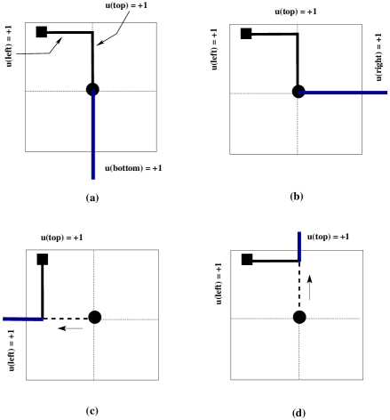
In Fig. 5, we illustrate the routing demand for each boundary of a bin after local routing of a net is performed within the bin. This example shows that the position of the pin (junction) in one of the four quadrants of the bin and the global route of the net terminating on the bin center determine the reservation of routing demand of the corresponding boundary edges; example (a) shows that unit routing demands in the top and left edge are reserved for local routing while bottom edge demand is meant for global route, (b) uses the same like in (a) but with right edge for global route. The example of (c) and (d) are special cases that are closely related to the edge being used for global route with respect to the position of the pin (junction). While the local routing instance in (c) shows that it utilizes the same left edge capacity for both local route and the global route segments and top edge capacity for vertical demand of the local route, (d) depicts a similar case for the global route at the top edge share with vertical segment of the local route, and left edge for horizontal segment of the local route. In these cases, no other edge capacity is relevant and hence not reserved as dictated by zero values in the demand in these edges. In this example, we also note that the wirelength is further minimized (as dictated by the arrow and the dotted line) due to common segment length between global and local routes.
2.5. Illustration of the proposed routing method
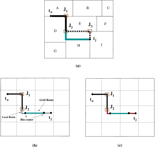
We illustrate the working of the proposed early global routing method HGR in Fig. 6 using a -terminal net (, ). In this example, we assume that this routing method considers only (, ) pair for routing through the monotone staircase regions only, due to the inherent routing blocks due to the macro/soft blocks. As in Fig. 6 (a), there are two routing paths between the terminal pair:
(i) as per STAIRoute (Kar
et al., 2013) obtains (, , , , ) of the net is entirely confined within the monotone staircase routing regions, i.e. through the boundary regions, as denoted partially by black solid line as (, , ) and dashed line (, , ). This is also illustrated earlier in Fig. 3 (a) by an entirely solid poly-line, by visualizing the dashed poly-line as solid.
(ii) here dotted line is used to denote illustrated that this path is congested in lower metal layer pair say (, ) and this framework is capable of finding an alternative path through the higher routing layers (say and above), but over the block . Notably, STAIRoute would route the partial routing segment, denoted as the dashed line (, , ), in higher layer pairs say (, ). This is due to the fact that its routing model is based only on the Junction graph model which allows routing through the monotone staircase boundary regions only.
Despite that, both the routing paths incur same wirelength and via count for same number of layer switch, providing more options of alternative routing paths without having any additional routing cost. On the contrary, if STAIRoute is not able to route along (, , ) in either or or both due to prevailing congestion scenario, subsequent permissible layer(s) and hence more vias will be used for this interconnection. But HGR will use the free region over the block in (, ) layer pair only. This implies that fewer metal layers may be used by HGR for overall routing completion as compared to STAIRoute.
For utilizing the free space over the block , Fig. 6 (b) shows how this hybrid routing graph model helps in identifying the remaining routing path () through the routing bins in upper metal layers (, ) with the help of the grid graph model used in it. Although, the grid graph model obtains a routing path between the centers of a pair of bins, where one bin belongs to while the other contains . Till now, the routing between the respective bin centers and () are not done. This is an example of pin-access problem, also commonly known as intra-bin or local routing problem. The third instance in Fig. 6 (c) shows the local routing between with one bin center and with the other bin center, both are done in (, ) pair, with the help of the corresponding pin/junction to G-Cell edges (in ).
2.6. The Algorithm: HGR
In Algorithm 1, we summarize the steps for the proposed early global routing method HGR (Hybrid Global Router). Similar to STAIRoute (Kar et al., 2013), Dijkstra’s shortest path algorithm (Cormen et al., 2009) is used to identify the shortest routing path of a -terminal net (segment) in the proposed hybrid routing graph. We also use a similar multi-terminal net decomposition approach in order to identify -terminal net segments as proposed in (Kar et al., 2013), for the identification of the Steiner tree topology. The set of nets are ordered first according to net-degree, and then HPWL in the given floorplan based on the bipartition hierarchy. This algorithm takes the junction graph and the grid graph as inputs which are already obtained using the floorplan bipartitioning results obtained by one of the existing works (Kar et al., 2014, 2015) with suitable trade-off values for minimal bend routing. For multi-terminal nets, we use a multi-terminal net decomposition method similar to that proposed in (Kar et al., 2013). According to this method, for each valid terminal pair, i.e., the valid edge in the resulting spanning tree, we apply this two terminal hybrid routing method, followed by Steiner point identification.
After successful routing of a net , the capacity of the corresponding segments in the monotone staircases and grid edges along the routing path of is updated by . In this work, we assume that the pins of a block are located in metal layer or . The pins residing in lower metal group (, ) are associated with the junction graph, as shown in Fig. 6, forming pin-junction edges similar to the graph model used in STAIRoute. The pin-bin and junction-bin edges in are constructed by identifying the pins/junctions within the corresponding bin, by overlaying the grid graph on the junction graph. The routing cost of these edges, being the vertical connecting edges between and , is simply the planner length between the pin/junction location and the center of the bin and the number of vias incurred due to routing through multiple layer groups.
Alike the existing post-placement global routers, no capacity constraints for these edges are considered as congestion through these vertical edges has little significance, except via overhead. The main contribution in this work is that we use for identifying the (partial) routing path of in lower group of metal layers such as - only, while is used to route those nets in the subsequent higher metal layers beyond . The routing through the grid graph takes place when a segment of a net cannot be completed in - layers, obeying the congestion model in the corresponding rectilinear staircase segments. Although (, ) layer pairs have been used in this work, additional layer pairs such as (, ), (, ) etc. can be used until (, ). When (, ) is also used, this model resembles with STAIRoute leading to no over-the-block early global routing possible in the floorplans.
Theorem 2.2.
Given a floorplan with blocks and nets with at most -terminals (), HGR takes time for finding the routing path of all the nets.
Proof.
For a given net with pins (terminals), there are pin-junctions edges as per Lemma in (Kar et al., 2013). Again, for routing bins, with pins and vertices in , pin-bin edges and junction-bin edges can be obtained. For each net , using Lemma , the hybrid GSRG construction takes , i.e., time, since = .
Alike STAIRoute, our implementation of Dijkstra’s single source shortest path algorithm takes time. For -terminal nets, both the construction of and finding its MST require time (see (Kar et al., 2013)). Therefore, finding a routing path for a terminal net requires , i.e., time. Hence HGR takes time for routing nets. ∎
It is evident from Theorem 2.2 that HGR presented in Algorithm 1 has the same time complexity as that of STAIRoute, with a constant time overhead for the construction of the grid graph and identification of the pin (junction)-bin edges. This also takes into account the routing demand update in each of the edges in the hybrid graph pertaining to both the junction graph and the grid graph, once a net is routed successfully.
2.7. Early Abstraction of Edge Placement Error
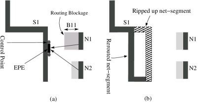
In this section, we study how edge placement errors (EPE) (Ding et al., 2011; Cho et al., 2009b; Mitra et al., 2005) occur due to inefficient printability issues of sub-wavelength features using the existing optical illumination system using wavelength. These errors are further aggravated due to the congestion scenario in the routing regions. The intensity map in Fig. 7 (a) depicts that the intensity is not uniform under the mask opening while the same is not zero beyond the mask opening. Therefore, it signifies additional metal width of the wire segment beyond its contour (see Fig. 7 (b)). Thus, if a routing region is more congested, there is little scope to cope up with EPE than doing ripup and reroute for some of the nets (or a part of it), as illustrated in Fig. 7 (b). Moreover, EPE related routing blockage to other nets may leave little room for the detailed routing of the adjacent nets. If this problem is neglected during the detailed routing stage, it will cause a failure during DFM closure stage.
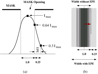
The intensity map in Fig. 7 (a) depicts the maximum intensity at the center of the mask opening (Mitra et al., 2005) and the intensity falls off gradually in a pattern similar to = function, where is the distance measured from the center of the mask opening. Notably, the intensity at the mask boundary (edge) is around of . The intensity gradient across the width (dictated by an arrow in Fig. 7 (b)) signifies the intensity deficiency causing optical proximity errors (OPE). In this model, we consider only the EPE effect in our early routing model in HGR due to nonzero intensity beyond mask opening as the OPE effect due to the said intensity gradient can not be modeled without proper simulation or rule definition at this early stage of physical design flow. According to (Mitra et al., 2005), we consider the threshold point for EPE as the point where the intensity falls to of , in the region beyond the mask edge, i.e., beyond the wire boundary contour. It amounts to approximately increase in effective metal width on either side of the wire. As a result, it has more interfering effects on the neighboring wire segments of other nets, called EPE induced routing blockage, due to the effect of positive optical interference. This kind of violation due to EPE is discovered during optical rule check (ORC) in the physical verification process of the existing physical design flow. In this case, either wire spreading or rip-up and re-route methods are applied in order to minimize number of such violations.
In order to incorporate this EPE effect in our early global routing framework HGR, we abstract this effect in the routing demand for assessing the congestion scenario in any metal layer at any given routing instance. This early abstraction of EPE into our proposed routing framework HGR has the potential to reduce the lithography hot-spots due to EPE routing blockage (see Fig. 8 (a)) at the smaller technology nodes after the detailed routing stage. Therefore, it will reduce the potential overhead of multiple iterations due to wire-spreading or ripup and reroute (RR) during detailed routing (see Fig. 8 (b)) for EPE hotspor reduction (Ding et al., 2011; Cho et al., 2009b; Mitra et al., 2005). In the congestion model of HGR, the penalty due to this EPE cost abstraction is incorporated as follows: after each net is routed through the routing region , its routing demand is incremented by considering the effect of additional metal on the either side. After routing a net , the congestion in the corresponding routing resources along its routing path are computed. The routing graph (hGSRG) for the subsequent net is constructed in order to identify the routing path for it along with the present layer wise congestion scenario in the routing regions.

Due to this process, there will potentially be fewer nets to be ripped up aimed at EPE hotspot reduction during post-routing/layout optimization. The example in Fig. 9 (a) showcases this considering six tracks () for routing the nets, without accounting for EPE effect. However, some of the nets, in tracks and shown in this example, may be ripped up later during EPE aware routing optimization. On the other hand, as depicted in Fig. 9 (c), the proposed EPE aware early routing framework with extended pitch, which accounts for taking as for each net routed in region than using when EPE is not considered, routes only those nets, such as those remained in tracks , after ripping up the other two nets during the existing methods for EPE hotspot reduction. This example shows that a routing solution considering such an early model may potentially reduce the overhead of multiple iterations due to (i) first routing the nets, and (ii) then ripping some of them up in an attempt towards EPE hotspot reduction.
3. Experimental Results
In this paper, we used IBM HB floorplanning benchmarks (hbe, [n. d.]) presented in Table 1 for verifying the proposed early global routing method HGR presented in Algorithm 1. These benchmarks were derived from ISPD98 placement benchmark circuits with certain modifications (hbe, [n. d.]), in order to form a set of clusters from the standard cells present in the placement benchmark circuits. These clusters not only defined a set of soft blocks, it also helps in defining a subset of the original netlist as the interconnection between the macros and these soft blocks. Notably, these interconnections represent relatively larger nets, some are partial though, barring the standard cell connectivity of the original nets defined in the design. As a result, these modified nets terminate at the boundaries of the macros/soft blocks.
| Circuit | #Blocks | #Nets | Avg. | HPWL |
|---|---|---|---|---|
| Name | NetDeg | (m) | ||
| ibm01 | 2254 | 3990 | 3.94 | 8.98 |
| ibm02 | 3723 | 7393 | 4.84 | 22.19 |
| ibm03 | 3227 | 7673 | 4.18 | 23.83 |
| ibm04 | 4050 | 9768 | 3.92 | 30.82 |
| ibm05 | 1612 | 7035 | 5.58 | 18.12 |
| ibm06 | 1902 | 7045 | 4.92 | 21.78 |
| ibm07 | 2848 | 10822 | 4.44 | 42.48 |
| ibm08 | 3251 | 11250 | 4.92 | 46.57 |
| ibm09 | 2847 | 10723 | 4.08 | 48.35 |
| ibm10 | 3663 | 15590 | 3.85 | 121.23 |
These floorplan instances were generated using Parquet (Adya and Markov, 2003; par, [n. d.]) using random seed for each of the circuits, i.e., to . The proposed algorithm HGR was implemented in C programming language and the experiments were conducted on a Linux platform having Intel Xeon processor running at GHz and has GB RAM in it. Since IBM benchmarks (hbe, [n. d.]) do not provide any pin location details, both STAIRoute and HGR assumed the pins of the blocks connected to the nets at the center of the blocks. A maximum of eight metal layers were permitted to be used for routing the floorplan level nets, using preferred routing directions as horizontal/vertical in odd/even layers. It is also assumed that only two metal layers ( and only) out of all the available layers were reserved for internal routing of the macros/soft blocks. For fair comparison, we reran STAIRoute (Kar et al., 2013) with these benchmarks, as the results reported in (Kar et al., 2013) were obtained for much smaller floorplanning benchmark circuits (par, [n. d.]).
3.1. Comparison with Existing Early Global Router STAIoute
First, we present a comparative study between the experimental results obtained by HGR and STAIRoute (Kar et al., 2013). In this comparison, we consider both with and without abstracted EPE cost in the congestion model (see Eqn. 1), discussed in the previous section. With these experiments, our aim is study the effectiveness of the proposed generic early global routing framework, which supports over-the-block routing beyond some predefined routing layer, with respect to the existing work STAIRoute (Kar et al., 2013). In addition to that, we also aimed to incorporate an early abstraction of EPE cost in the routing penalty for both HGR and STAIRoute, as outlined in (Kar et al., 2016) and also presented in the previous section in details. The corresponding results are presented in Table 2, for (a) netlength, (b) via count, and (c) average worst congestion (Wei et al., 2012).
These results were obtained for routing completion of the nets using up to eight routing layers, ensuring no over-congestion as per the congestion model defined in Eqn. 1. The results obtained for netlength shows almost identical values obtained by these early global routers for both without and with EPE cost in the routing penalty; HGR shows a slight improvement with an average of and reduction in wirelength over STAIRoute for both with and without EPE cost respectively. Although both these routers tend to confine the routing paths within the bounding box using one/two/more bends (monotone patterns), the overall netlength varies due to the non-overlapping (non-common) wire segments through the same or different metal layers, as obtained by the multi-terminal net decomposition method (see (Kar et al., 2013) for details). This is apparent as HGR has fewer layer change due to over-the-block routing approach, while STAIRoute uses more layer changes while confining the routing path through the monotone staircase boundary regions only. Accordingly, via count for HGR also shows significant average reduction of and respectively over STAIRoute for both the cases, due to fewer layer changes among the wire segments of a net or subnet.
| Circuit | Length() | Via Count() | Worst Avg. Congestion () | |||||||||
|---|---|---|---|---|---|---|---|---|---|---|---|---|
| Name | STAIRoute (Kar et al., 2013) | HGR | STAIRoute (Kar et al., 2013) | HGR | STAIRoute (Kar et al., 2013) | HGR | ||||||
| +EPE | +EPE | +EPE | +EPE | +EPE | +EPE | |||||||
| ibm01 | 11.44 | 11.47 | 11.35 | 11.16 | 2.16 | 2.19 | 1.08 | 1.05 | 0.750 | 0.282 | 0.101 | 0.146 |
| ibm02 | 32.18 | 32.27 | 30.73 | 31.26 | 6.17 | 6.28 | 2.82 | 2.79 | 0.917 | 0.294 | 0.100 | 0.135 |
| ibm03 | 35.60 | 35.84 | 32.08 | 33.95 | 5.44 | 5.59 | 2.42 | 2.43 | 0.935 | 0.714 | 0.104 | 0.128 |
| ibm04 | 39.13 | 39.23 | 39.58 | 37.95 | 7.20 | 7.30 | 3.33 | 3.25 | 0.524 | 0.786 | 0.115 | 0.138 |
| ibm05 | 26.43 | 26.45 | 25.94 | 25.73 | 4.01 | 4.06 | 2.08 | 2.11 | 0.203 | 0.277 | 0.108 | 0.158 |
| ibm06 | 31.20 | 31.24 | 30.72 | 30.80 | 4.27 | 4.33 | 2.12 | 2.14 | 0.773 | 0.955 | 0.124 | 0.154 |
| ibm07 | 56.70 | 56.80 | 56.44 | 54.72 | 7.83 | 7.93 | 3.61 | 3.51 | 0.244 | 0.320 | 0.094 | 0.120 |
| ibm08 | 67.81 | 68.06 | 62.78 | 64.64 | 9.35 | 9.52 | 4.09 | 4.21 | 0.647 | 0.569 | 0.082 | 0.117 |
| ibm09 | 63.66 | 63.79 | 62.15 | 61.13 | 7.08 | 7.17 | 3.28 | 3.22 | 0.789 | 0.750 | 0.103 | 0.136 |
| ibm10 | 153.37 | 154.04 | 141.01 | 133.30 | 10.70 | 11.02 | 4.90 | 4.74 | 0.249 | 0.575 | 0.110 | 0.156 |
| Norm. | ||||||||||||
| Geo. | 1.000 | 1.003 | 0.964 | 0.957 | 1.000 | 1.017 | 0.470 | 0.465 | 1.000 | 0.948 | 0.197 | 0.259 |
| Mean | ||||||||||||
In this table, we also present the congestion values measured as the worst average congestion in terms of a parameter called , showing an average reduction of to in case of HGR as compared to that in STAIRoute, in both cases of with and without EPE cost. In this paper, the congestion analysis is motivated by the approach proposed in GLARE (Wei et al., 2012). The authors in (Wei et al., 2012) defined a parameter called (Average Congestion on Edges) computed for the worst congested edges among all routing layers and the prescribed values of are one of the values belonging to . In our analysis, we compute an average of for all the prescribed values and term it average worst congestion . This congestion analysis shows that HGR considers a more realistic approach similar to that adopted to by the post-placement global routing methods, while STAIRoute assesses only congestion in the regions designated as the monotone staircase boundary regions in the floorplan. The congestion values obtained by STAIRoute and hence HGR for lower layers is justified for the lower layer pair (, ) due to the assumption that a very small fraction of of the total layout area is available as the effective routing space, because of the routing space reservation for internal routing in the soft blocks and also the macros whose internal routing has already been done using these two layers. As per this assumption, layers beyond have plenty of free space of the blocks which are effectively used by HGR, while STAIRoute can not use those free space because of its routing model.
| Circuit | #Routing-layers | CPU time (sec) | ||||||
| Name | STAIRoute (Kar et al., 2013) | HGR | STAIRoute (Kar et al., 2013) | HGR | ||||
| +EPE | +EPE | +EPE | +EPE | |||||
| ibm01 | 6 | 8 | 4 | 4 | 2.822 | 2.763 | 10.273 | 10.479 |
| ibm02 | 6 | 6 | 4 | 4 | 16.359 | 17.144 | 63.529 | 69.391 |
| ibm03 | 6 | 6 | 4 | 4 | 10.884 | 11.655 | 43.393 | 47.748 |
| ibm04 | 6 | 6 | 4 | 4 | 21.364 | 23.454 | 90.265 | 81.634 |
| ibm05 | 6 | 6 | 4 | 4 | 2.799 | 2.841 | 11.375 | 11.502 |
| ibm06 | 6 | 8 | 4 | 6 | 3.673 | 3.787 | 14.915 | 15.311 |
| ibm07 | 8 | 8 | 6 | 6 | 12.163 | 12.423 | 51.911 | 50.152 |
| ibm08 | 8 | 8 | 6 | 6 | 18.102 | 18.087 | 76.065 | 73.402 |
| ibm09 | 8 | 8 | 6 | 6 | 11.281 | 11.360 | 46.418 | 47.728 |
| ibm10 | 8 | 8 | 6 | 8 | 26.387 | 27.888 | 126.338 | 126.978 |
| Norm. | ||||||||
| Geo. | 1.000 | 1.029 | 0.700 | 0.749 | 1.000 | 1.032 | 4.114 | 4.157 |
| Mean | ||||||||
Table 3 presents the number of metal layers used out of maximum permissible layers and the runtime for routing in seconds, for STAIRoute anbd HGR using both with and without EPE costs. These results show that the number of routing layers used for each circuit in case of HGR are fewer than that for STAIRoute, considering all the cases. One notable point here is that, for both HGR and STAIRoute, slightly higher number of layers are required in order to obtain when EPE cost is incorporated in the routing penalty. Lastly, as discussed earlier in this paper (see Theorem 2.2), the results also show that HGR needs approximately a constant more runtime over STAIRoute to route the same set of nets for the same floorplan instance.
3.2. Comparison with Post-placement Global Routers
In Table 4, we present a comparison of the normalized netlength for some of the existing post-placement global routers (Cho et al., 2009a; Moffitt, 2008; Ozdal and Wong, 2009; Zhang et al., 2008; Roy and Markov, 2008; Chang et al., 2010) and the proposed early global routing methods STAIRoute and HGR, based on the corresponding benchmark circuits. Notably, the results for the existing global routers were obtained on IBM ISPD98 placement benchmarks, while HGR and STAIRoute (Kar et al., 2013) obtained the corresponding results on IBM-HB floorplanning benchmarks derived from it (hbe, [n. d.]). As cited earlier, a floorplanning benchmark is obtained from a placement benchmark circuit using suitable clustering algorithm, the IBM-HB floorplanning benchmarks were derived from the ISPD98 placement benchmarks (hbe, [n. d.]). This conversion incurs significant information loss due to standard cell clustering and the corresponding netlist modification. Therefore, it is unfair to compare the actual netlength obtained for the respective circuits by both the frameworks. Instead, the netlength obtained for each circuit is normalized with respect to the respective Steiner length computed by Flute (Chu and Wong, 2008). The results in this table for both STAIRoute and HGR are slightly higher as the nets are routed through the monotone staircase routing regions only for STAIRoute in all the routing layers, while HGR incurred sightly lower netlength value than STAIRoute due to the proposed over-the-block routing approach. However, as we pointed out earlier, the post-placement routers considered all the nets, including the standard cell connectivity, unlike STAIRoute and HGR. Moreover, both STAIRoute and HGR addressed intra-bin/local routing for pin accessibility at the floorplan level, unlike in post-placement global routing which push the pin-accessibility issue to the detailed routing stage. In summary, the main purpose of this study is to understand how these early global routing approaches can assess initial routing metrics like netlength while ensuring routing completion, in terms of the deviation of the overall netlength from the Steiner length without considering any routing blockage. The results show that HGR and STAIRoute deviate and from their respective Steiner length, for the corresponding floorplan instances of each circuit. This implies that there is a scope of improvement in the floorplan topology, such as clustering of standard cells and most importantly the locations of the macros/soft blocks), for enhancing the routing performance by using these early routing results in floorplan optimization tools such as Parque (par, [n. d.]).
| Circuit | Post-placement Global Routers | Early Global Routers | ||||||
|---|---|---|---|---|---|---|---|---|
| Name | (Ozdal and Wong, 2009)b | (Cho et al., 2009a)b | (Zhang et al., 2008)b | (Roy and Markov, 2008)b | (Moffitt, 2008)b | (Chang et al., 2010)b | STAIRoute(Kar et al., 2013)c | HGRc |
| ibm01 | 1.071 | 1.042 | 1.068 | 1.053 | 1.059 | 1.039 | 1.156 | 1.147 |
| ibm02 | 1.036 | 1.032 | 1.038 | 1.018 | 1.027 | 1.024 | 1.175 | 1.121 |
| ibm03 | 1.007 | 1.007 | 1.007 | 1.005 | 1.010 | 1.005 | 1.175 | 1.059 |
| ibm04 | 1.045 | 1.028 | 1.046 | 1.027 | 1.045 | 1.023 | 1.155 | 1.169 |
| ibm05d | - | - | - | - | - | - | 1.198 | 1.176 |
| ibm06 | 1.011 | 1.007 | 1.013 | 1.006 | 1.013 | 1.007 | 1.166 | 1.148 |
| ibm07 | 1.018 | 1.006 | 1.015 | 1.007 | 1.016 | 1.007 | 1.192 | 1.187 |
| ibm08 | 1.005 | 1.008 | 1.009 | 1.006 | 1.010 | 1.006 | 1.197 | 1.109 |
| ibm09 | 1.007 | 1.006 | 1.009 | 1.004 | 1.011 | 1.008 | 1.199 | 1.171 |
| ibm10 | 1.016 | 1.027 | 1.015 | 1.008 | 1.020 | 1.010 | 1.187 | 1.200 |
| Average | 1.024 | 1.018 | 1.024 | 1.015 | 1.024 | 1.014 | 1.180 | 1.149 |
- using ISPD98 global routing benchmarks, - using IBM-HB floorplanning benchmarks, and - no result on of ISPD98 benchmark by the existing global routers
In the post-placement global routing framework, congestion analysis is done by the number of overflows in the routing edges. On contrary, we used a relative congestion metric (see Eqn. 2) inspired by GLARE (Wei et al., 2012). In this work, we adopted a congestion analysis method using the parameters defined in (Wei et al., 2012) as our congestion model (see Eqn. 1) does not allow overflow (routing demand exceeding the routing capacity) based computation. Due to this reason, we could not make any direct comparison on congestion overflow for each circuit. Later in this section, we present some overflow based congestion results obtained for some industrial design inputs by an industrial tool which reports both versions of congestion analysis. We also skip the comparison for via counts as both these frameworks are in different scope of operation as per the PD flow. In this comparison, we used only ISPD98 benchmarks whose corresponding IBM-HB floorplanning benchmarks (hbe, [n. d.]) are the latest ones available for academic research. We are not able to compare the routing results for the latest ISPD07/08 global routing benchmarks, since the corresponding floorplanning benchmarks are not available online. In order to study the effectiveness of the proposed early global routing method HGR with respect to the existing post-placement global routing paradigm, we subsequently present a case study with a well known industrial physical design (PD) tool.
3.3. An Industrial Case Study
In order to study the impact of early global routing presented in this work (also in (Kar et al., 2013) on the existing physical design flow, we conducted an industrial case study by developing a framework that can integrate HGR (and also STAIRoute) with industrial PD tool Olympus-SoC (oly, [n. d.]), as outlined in Fig. 10. This framework consists of an interface for industry standard LEF/DEF exchange format between STAIRoute/HGR and Olympus tool. In this study, we used a design to be implemented with a physical design library (nan, [n. d.]), while the physical verification was done by Calibre tool suite (cal, [n. d.]).

In this exercise started with a floorplan instance of a design generated by Olympus-SoC tool. Default placement constraints were used for the subsequent placement engine and the design utilization target was set at . Subsequent stages in Olympus implemented the design as per Fig. 10, having no early routability assessment done on the floorplan. In another attempt, STAIRoute/HGR obtained the same floorplan instance through the LEF/DEF interface and obtained the early global routing solution for randomly chosen (, ) values such as (, ) used to obtain the recursive floorplan bipartitioning results (Kar et al., 2014) and define the routing regions. For routing, we used metal layers using preferred routing directions in each layer, horizontal being on the odd layer and vertical on the even, as supported by the given technology. In this study, we emphasized on timing driven placement and hence on parameters like TNS/WNS. Using both the approaches in Olympus, i.e. with and without early global routing, we obtained the final layout with no DRC/LVS violations, and also ensured zero timing violations in terms of non-negative WNS/TNS values. We used all other default values pertaining to Olympus-SoC tool for this exercise and noticed that timing was given more priority, than congestion/via minimization, using buffer insertion. This is the reason that Olympus tool used more buffer/inverter cells when STAIRoute was used. Hence more number of nets were introduced during timing driven standard cell placement, after early global routing (see Fig. 10 (b)). In all the cases, the target of placement density (utilization %) was met while no timing violations were reported, and non-negative WNS/TNS values were achieved subsequently. It is important to note here that, the present day design philosophy goes for fixed outlined layout with predefined layout area. Therefore, higher utilization value may sometime lead to infeasible, sometimes incomplete, routing solution due to either (i) maximum usage of higher number of layers, and (ii) even the maximum number of layers permissible by the technology is not sufficient.
| Parameter(s) | Olympus-SoC (oly, [n. d.]) | Olympus (oly, [n. d.]) | Olympus (oly, [n. d.]) |
|---|---|---|---|
| + STAIRoute (Kar et al., 2013) | + HGR | ||
| Standard Cells (Macros) | 16360 (4) | 16611 (4) | 16504 (4) |
| Nets | 16474 | 16725 | 16618 |
| Buffer/Inverter | 225/6527 | 225/6575 | 225/6441 |
| Placed Area (Buf area) () | 45909 (10104) | 45966 (10157) | 45834 (10018) |
| Utilization (%) | 59.17 | 59.24 | 59.07 |
| Wirelength(mm) | 273.02 | 273.52 | 273.43 |
| Via Count (x) | 52.80 | 53.13 | 52.84 |
| WNS/TNS (ns) | 0.00/0.00 | 0.00/0.00 | 0.00/0.00 |
| Avg. Congestion (X/Y) | 0.123/0.111 | 0.122/0.112 | 0.122/0.112 |
| Worst Congestion (X/Y) | 0.826/0.928 | 0.791/0.916 | 0.782/0.909 |
| Edge Overflow (X/Y) | 0/0 | 0/0 | 0/0 |
| DRC/LVS violations | No | No | No |
| # of Routing Layers | 8 | 8 | 8 |
| CPU time (sec) | 1979 | 688 | 699 |
The corresponding results are presented in Tab 5 for the given floorplan instance. For the results pertaining to early global routing, important observations can be made in worst/average congestion (in X/Y direction), via count, runtime and even timing despite insignificant increase (less than ) in cell and net count due to timing driven placement of standard cells by Olympus with early global routing than in standalone Olympus mode. Moreover, no DRC/LVS violations nor placement density constraint violations (utilization ) were noticed. Runtime for Olympus with STAIRoute/HGR is significantly improved due to fewer number of iterations in order to converge on an acceptable routing solution with no timing violations, being roughly three times faster than that for standalone Olympus, while results for HGR+Olympus are shown to be the best among all. Moreover, significant runtime improvement for the entire flow can also be noticed due to fewer number of iterations, as the timing driven placement optimization appears to have been guided by the early global routing results for both HGR and STAIRoute.
4. Conclusion
In this paper, we present a new early global routing framework that facilitates over-the-block early global routing of the nets in a given floorplan. In this work, layer is assumed to be the maximum routing layer used for internal routing for macros/soft block. While STAIRoute (Kar et al., 2013) identifies the routing paths of the nets through the monotone staircase routing regions in all routing layers, the proposed method HGR routes the nets through these regions only in lower metal layers (, ). For higher routing layers, i.e. beyond , HGR uses the free space over the blocks for routing the nets or parts of the nets. Alike STAIRoute, this model also attempts to address the pin access problem at the floorplan level by suitable edge definitions in the proposed hybrid routing graph, as presented in Section 2. Therefore, HGR can be seen as a generic version of STAIRoute. If the maximum layer assumed to be reserved for internal routing is taken as the maximum allowable routing layer, then there will be no free space of over the macro/soft blocks. This implies that all the nets are to be routed through the monotone staircase regions situated at the boundary regions of each of the blocks, and applicable for all layers.
Experimental results presented in Section 3 show that HGR obtains smaller wirelength, fewer via count and also less congestion as compared to STAIRoute, with a more realistic early global routing approach by obtaining over-the-block routing paths beyond a specific routing layer. These results also ensure that the congestion values are constrained to as per the proposed congestion model, with routability. A comparison with the existing post-placement global routers also show that, even without detailed placement of standard cells, the proposed early global routing approach HGR can have a good idea of routability, wirelength and congestion values in a given floorplan instead of using primitive metrics like half perimeter wirelength (HPWL) and pre-routing probabilistic congestion analysis. The industrial case study also indicates the potential of early global routing framework in guiding acceptable final routing solutions in fewer iterations, and with fewer/no violations due to design for manufacturibility issues and also leverage on minimalistic compromise on the performance metrics like speed, within a competitive time frame.
Based on the results from the industrial case study, we plan for a new placement and routing framework guided by this generic early global routing method for a given floorplan solution and subsequently incorporate the DFM issues with enhanced models using extensive simulations results for smaller VDSM process nodes. We also plan to explore the scope of this work in IC design flow.
References
- cal ([n. d.]) [n. d.]. Calibre Tool Suite, Mentor Graphics Inc. ([n. d.]). https://www.mentor.com/products/ic_nanometer_design/verification-signoff
- hbe ([n. d.]) [n. d.]. IBM-HB Floorplanning Benchmarks. ([n. d.]). https://cadlab.cs.ucla.edu/cpmo/HBsuite.html
- nan ([n. d.]) [n. d.]. NanGate OpenCell Library. ([n. d.]). http://www.nangate.com/?page_id=2325
- oly ([n. d.]) [n. d.]. Olympus-SoC tool, Mentor Graphics Inc. ([n. d.]). https://www.mentor.com/products/ic_nanometer_design/place-route/olympus-soc
- par ([n. d.]) [n. d.]. Parquet Floorplanner and MCNC/GSRC Floorplanning Benchmarks. ([n. d.]). https://vlsicad.eecs.umich.edu/BK/parquet
- Adya and Markov (2003) S. N. Adya and I. L. Markov. 2003. Fixed-outline floorplanning: Enabling hierarchical design. IEEE Transactions on Very Large Scale Integration (VLSI) Systems 11, 6 (Dec 2003), 1120–1135. https://doi.org/10.1109/TVLSI.2003.817546
- Alpert et al. (2013) C.J. Alpert, Z. Li, C.N. Sze, and Y. Wei. 2013. Consideration of local routing and pin access during VLSI global routing. (April 9 2013). http://www.google.ch/patents/US8418113 US Patent 8,418,113.
- Batterywala et al. (2002) S. Batterywala, N. Shenoy, W. Nicholls, and H. Zhou. 2002. Track assignment: a desirable intermediate step between global routing and detailed routing. In IEEE/ACM International Conference on Computer Aided Design, 2002. ICCAD 2002. 59–66. https://doi.org/10.1109/ICCAD.2002.1167514
- Cao et al. (2008) Z. Cao, T. T. Jing, J. Xiong, Y. Hu, Z Feng, L. He, and X. L. Hong. 2008. Fashion: A Fast and Accurate Solution to Global Routing Problem. Computer-Aided Design of Integrated Circuits and Systems, IEEE Transactions on 27, 4 (April 2008), 726–737. https://doi.org/10.1109/TCAD.2008.917590
- Chang et al. (2010) Y. J. Chang, Y. T. Lee, J. R. Gao, P. C. Wu, and T. C. Wang. 2010. NTHU-Route 2.0: A Robust Global Router for Modern Designs. IEEE Transactions on Computer-Aided Design of Integrated Circuits and Systems 29, 12 (Dec 2010), 1931–1944. https://doi.org/10.1109/TCAD.2010.2061590
- Chang and Lin (2004) Y. W. Chang and S. P. Lin. 2004. MR: a new framework for multilevel full-chip routing. Computer-Aided Design of Integrated Circuits and Systems, IEEE Transactions on 23, 5 (May 2004), 793–800. https://doi.org/10.1109/TCAD.2004.826547
- Chen and Chang (2009) H. Y. Chen and Y. W. Chang. 2009. Routing for manufacturability and reliability. IEEE Circuits and Systems Magazine 9, 3 (Third 2009), 20–31. https://doi.org/10.1109/MCAS.2009.933855
- Cho et al. (2009a) M. Cho, K. Lu, K. Yuan, and D. Z. Pan. 2009a. BoxRouter 2.0: A Hybrid and Robust Global Router with Layer Assignment for Routability. ACM Trans. Des. Autom. Electron. Syst. 14, 2, Article 32 (April 2009), 21 pages. https://doi.org/10.1145/1497561.1497575
- Cho et al. (2009b) M. Cho, K. Yuan, Y. Ban, and D.Z. Pan. 2009b. ELIAD: Efficient Lithography Aware Detailed Routing Algorithm With Compact and Macro Post-OPC Printability Prediction. Computer-Aided Design of Integrated Circuits and Systems, IEEE Transactions on 28, 7 (July 2009), 1006–1016. https://doi.org/10.1109/TCAD.2009.2018876
- Chu and Wong (2008) C. Chu and Y. C. Wong. 2008. FLUTE: Fast Lookup Table Based Rectilinear Steiner Minimal Tree Algorithm for VLSI Design. Computer-Aided Design of Integrated Circuits and Systems, IEEE Transactions on 27, 1 (Jan 2008), 70–83. https://doi.org/10.1109/TCAD.2007.907068
- Cong et al. (2005) J. Cong, J. Fang, M. Xie, and Y. Zhang. 2005. MARS- a multilevel full-chip gridless routing system. Computer-Aided Design of Integrated Circuits and Systems, IEEE Transactions on 24, 3 (March 2005), 382–394. https://doi.org/10.1109/TCAD.2004.842803
- Cormen et al. (2009) T. H. Cormen, C. E. Leiserson, R. L. Rivest, and C. Stein. 2009. Introduction to Algorithms (3rd ed.). MIT Press, Cambridge, MA, USA.
- Ding et al. (2011) D. Ding, J. R. Gao, K. Yuan, and D.Z. Pan. 2011. AENEID: A generic lithography-friendly detailed router based on post-RET data learning and hotspot detection. In Design Automation Conference (DAC), 2011 48th ACM/EDAC/IEEE. 795–800.
- Kar et al. (2013) B. Kar, S. Sur-Kolay, and C. Mandal. 2013. STAIRoute: Global routing using monotone staircase channels. In IEEE Computer Society Annual Symposium on VLSI, ISVLSI 2013, Natal, Brazil, August 5-7, 2013. 90–95.
- Kar et al. (2014) B. Kar, S. Sur-Kolay, and C. Mandal. 2014. Global Routing Using Monotone Staircases with Minimal Bends. In 2014 27th International Conference on VLSI Design, VLSID 2014, Mumbai, India, January 5-9, 2014. 369–374.
- Kar et al. (2015) B. Kar, S. Sur-Kolay, and C. Mandal. 2015. A New Method for Defining Monotone Staircases in VLSI Floorplans. In 2015 IEEE Computer Society Annual Symposium on VLSI, ISVLSI 2015, Montpellier, France, July 8-10, 2015. 107–112.
- Kar et al. (2016) B. Kar, S. Sur-Kolay, and C. Mandal. 2016. A Novel EPE Aware Hybrid Global Route Planner after Floorplanning. In 29th International Conference on VLSI Design, VLSID 2016, Kolkata, India, January 4-8, 2016. 595–596.
- Kar et al. (2012) B. Kar, S. Sur-Kolay, S. H. Rangarajan, and C. Mandal. 2012. A Faster Hierarchical Balanced Bipartitioner for VLSI Floorplans Using Monotone Staircase Cuts. In Progress in VLSI Design and Test - 16th International Symposium, VDAT 2012, Shibpur, India, July 1-4, 2012. Proceedings. 327–336.
- Kastner et al. (2002) R. Kastner, E. Bozorgzadeh, and M. Sarrafzadeh. 2002. Pattern routing: use and theory for increasing predictability and avoiding coupling. Computer-Aided Design of Integrated Circuits and Systems, IEEE Transactions on 21, 7 (Jul 2002), 777–790. https://doi.org/10.1109/TCAD.2002.1013891
- Li et al. (2007) Z. Li, C.J. Alpert, S.T. Quay, S. Sapatnekar, and W. Shi. 2007. Probabilistic Congestion Prediction with Partial Blockages. In Quality Electronic Design, 2007. ISQED ’07. 8th International Symposium on. 841–846. https://doi.org/10.1109/ISQED.2007.124
- Lin and Chu (2014) T. Lin and C. Chu. 2014. POLAR 2.0: An effective routability-driven placer. In Design Automation Conference (DAC), 2014 51st ACM/EDAC/IEEE. 1–6.
- Liu et al. (2013a) W. H. Liu, W. C. Kao, Y. L. Li, and K. Y. Chao. 2013a. NCTU-GR 2.0: Multithreaded Collision-Aware Global Routing With Bounded-Length Maze Routing. Computer-Aided Design of Integrated Circuits and Systems, IEEE Transactions on 32, 5 (May 2013), 709–722. https://doi.org/10.1109/TCAD.2012.2235124
- Liu et al. (2013b) W. H. Liu, C. K. Koh, and Y. L. Li. 2013b. Optimization of placement solutions for routability. In Design Automation Conference (DAC), 2013 50th ACM/EDAC/IEEE. 1–9.
- Majumder et al. (2004) S. Majumder, S. Sur-Kolay, S. C. Nandy, and B. B. Bhattacharya. 2004. On Finding a Staircase Channel with Minimum Crossing Nets in a VLSI Floorplan. Journal of Circuits, Systems and Computers 13, 05 (2004), 1019–1038. https://doi.org/10.1142/S0218126604001854 arXiv:http://www.worldscientific.com/doi/pdf/10.1142/S0218126604001854
- Mitra et al. (2005) J. Mitra, P. Yu, and D.Z. Pan. 2005. RADAR: RET-aware detailed routing using fast lithography simulations. In Design Automation Conference, 2005. Proceedings. 42nd. 369–372. https://doi.org/10.1109/DAC.2005.193836
- Moffitt (2008) M. D. Moffitt. 2008. MaizeRouter: Engineering an Effective Global Router. IEEE Transactions on Computer-Aided Design of Integrated Circuits and Systems 27, 11 (Nov 2008), 2017–2026. https://doi.org/10.1109/TCAD.2008.2006082
- Ozdal and Wong (2009) M. M. Ozdal and M. D. F. Wong. 2009. Archer: A History-Based Global Routing Algorithm. IEEE Transactions on Computer-Aided Design of Integrated Circuits and Systems 28, 4 (April 2009), 528–540. https://doi.org/10.1109/TCAD.2009.2013991
- Pan and Chu (2006) M. Pan and C. Chu. 2006. FastRoute: A Step to Integrate Global Routing into Placement. In Computer-Aided Design, 2006. ICCAD ’06. IEEE/ACM International Conference on. 464–471. https://doi.org/10.1109/ICCAD.2006.320159
- Pan and Chu (2007) M. Pan and C. Chu. 2007. IPR: An Integrated Placement and Routing Algorithm. In Design Automation Conference, 2007. DAC ’07. 44th ACM/IEEE. 59–62.
- Roy and Markov (2008) J.A. Roy and I.L. Markov. 2008. High-Performance Routing at the Nanometer Scale. Computer-Aided Design of Integrated Circuits and Systems, IEEE Transactions on 27, 6 (June 2008), 1066–1077. https://doi.org/10.1109/TCAD.2008.923255
- Sherwani (1995) N. A. Sherwani. 1995. Algorithms for VLSI Physical Design Automation (2nd ed.). Kluwer Academic Publishers, Norwell, MA, USA.
- Sur-Kolay and Bhattacharya (1991) S. Sur-Kolay and B. B. Bhattacharya. 1991. The cycle structure of channel graphs in nonsliceable floorplans and a unified algorithm for feasible routing order. In IEEE International Conference on Computer Design: VLSI in Computers and Processors. 524–527. https://doi.org/10.1109/ICCD.1991.139964
- Viswanathan and Chu (2005) N. Viswanathan and C. Chu. 2005. FastPlace: efficient analytical placement using cell shifting, iterative local refinement,and a hybrid net model. Computer-Aided Design of Integrated Circuits and Systems, IEEE Transactions on 24, 5 (May 2005), 722–733. https://doi.org/10.1109/TCAD.2005.846365
- Wei et al. (2012) Y. Wei, C. Sze, N. Viswanathan, Z. Li, C.J. Alpert, L. Reddy, A.D. Huber, G.E. Tellez, D. Keller, and S.S. Sapatnekar. 2012. GLARE: Global and local wiring aware routability evaluation. In Design Automation Conference (DAC), 2012 49th ACM/EDAC/IEEE. 768–773.
- Westra et al. (2004) J. Westra, C. Bartels, and P. Groeneveld. 2004. Probabilistic Congestion Prediction. In Proceedings of the 2004 International Symposium on Physical Design (ISPD ’04). ACM, New York, NY, USA, 204–209. https://doi.org/10.1145/981066.981110
- Xu and Chu (2011) Y. Xu and C. Chu. 2011. MGR: Multi-level global router. In Computer-Aided Design (ICCAD), 2011 IEEE/ACM International Conference on. 250–255. https://doi.org/10.1109/ICCAD.2011.6105336
- Xu et al. (2009) Y. Xu, Y. Zhang, and C. Chu. 2009. FastRoute 4.0: Global router with efficient via minimization. In Design Automation Conference, 2009. ASP-DAC 2009. Asia and South Pacific. 576–581. https://doi.org/10.1109/ASPDAC.2009.4796542
- Zhang and Chu (2012) Y. Zhang and C. Chu. 2012. GDRouter: Interleaved global routing and detailed routing for ultimate routability. In Design Automation Conference (DAC), 2012 49th ACM/EDAC/IEEE. 597–602.
- Zhang and Chu (2013) Y. Zhang and C. Chu. 2013. RegularRoute: An Efficient Detailed Router Applying Regular Routing Patterns. Very Large Scale Integration (VLSI) Systems, IEEE Transactions on 21, 9 (Sept 2013), 1655–1668. https://doi.org/10.1109/TVLSI.2012.2214491
- Zhang et al. (2008) Y. Zhang, Y. Xu, and C. Chu. 2008. FastRoute3.0: A fast and high quality global router based on virtual capacity. In Computer-Aided Design, 2008. ICCAD 2008. IEEE/ACM International Conference on. 344–349. https://doi.org/10.1109/ICCAD.2008.4681596