Improving mixing characteristics with a pitched tip in kneading elements in twin-screw extrusion
Abstract
In twin-screw extrusion, the geometry of a mixing element mainly determines the basic flow pattern, which eventually affects the mixing ability as well as the dispersive ability of the mixing element. The effects of geometrical modification, with both forward and backward pitched tips, of a conventional forwarding kneading disks element (FKD) in the pitched-tip kneading disks element on the flow pattern and mixing characteristics are discussed. Numerical simulations of fully-filled, non-isothermal polymer melt flow in the melt-mixing zone were performed, and the flow pattern structure and the tracer trajectories were investigated. The pitched tips largely affects the inter-disc fluid transport, which is mainly responsible for mixing. These changes in the local flow pattern are analyzed by the distribution of the strain-rate state. The distribution of the finite-time Lyapunov exponent reveals a large inhomogeneity of the mixing in FKD is suppressed both by the forward and backward tips. By the forward tips on FKD, the mixing ability is relatively suppressed compared to FKD, whereas for the backward tips on FKD, the mixing ability is enhanced while maintaining the same level of dispersion efficiency as FKD. From these results, the pitched tips on the conventional KD turns out to be effective at reducing the inhomogeneity of the mixing and tuning the overall mixing performance.
I Introduction
The mixing of highly viscous materials, as well as low-viscous liquids, is one of the most important processes in chemical engineering. Twin-screw devices such as twin-rotor mixers and twin-screw extruders are widely applied in the mixing processes of highly viscous materials, including polymer processing, rubber compounding, and food processing Tadmor2006Principles ; Kohlgruber2007CoRotating ; White2010Twin ; 2011Food ; Rauwendaal2014Polymer . For twin-screw extrusion, various types of mixing elements have been developed for different mixing qualities as well as different processabilities of the materials, since the geometry of the mixing elements mainly determines the characteristics of the mixing process Kohlgruber2007CoRotating . In the development of a mixing element, one fundamental issue is a systematic understanding of the relation between the flow pattern driven by the mixing element and the mixing characteristics.
To understand the mixing abilities of different elements, experimental and numerical analyses of the flow in twin-screw extrusion have been performed Christiano1993J ; Lawal1995Mechanisms ; Lawal1995Simulation ; Cheng1997Study ; Carneiro1999Flow ; Shearer1999Analysis ; Alsteens2004Parametric ; Jaffer2000Experimental ; Bravo2000Numerical ; Shearer2000Effects ; Shearer2001Distributive ; Shearer2001Relationship ; Nakayama2011Meltmixing ; Kubik2012Method ; Hirata2014Effectiveness ; Zhang2009Numerical ; SarhangiFard2013Simulation ; Yamada2015Dispersive ; Nakayama2016Strain ; Nakayama2016Effects . A most common mixing element is the kneading block or kneading discs element (KD), which is composed of the several oval discs combined with a certain stagger angle Kohlgruber2007CoRotating . Mixing with kneading blocks in twin-screw extruders has been experimentally assessed by analyzing the distribution of tracers or interfaces. Christiano analyzed the distribution of carbon black in the extrudates with the intensity of segregation Christiano1993J . Shearer and Tzoganakis Shearer1999Analysis ; Shearer2000Effects ; Shearer2001Distributive ; Shearer2001Relationship used a reactive tracer to quantify the interface generation by distributive mixing. They reported that forward KDs have good distributive mixing in comparison with reverse and neutral KDs Shearer1999Analysis ; Shearer2000Effects ; Shearer2001Relationship . They also reported that the correlation between the mean residence time and the mixing ability holds for the reverse and neutral KD while the forward KD have a different dependence on the residence time Shearer2000Effects . Numerical simulations have been applied to analyze the flow and mixing in the kneading block zone. The important effect of the boundary conditions on the flow in the kneading block zone was suggested Jaffer2000Experimental . Bravo, Hrymak, and Wright reported a comparison between the results from the numerical simulation and experimental one McCulloughSPE , showing a good agreement of the pressure and velocity fields in most of the KD zone Bravo2000Numerical .
By modifying the angle of the tips in each disc of KD, a refined geometry called “pitched-tip kneading disks element” has been developed. In previous works Nakayama2011Meltmixing ; Nakayama2016Effects , the different mixing characteristics of ptKDs have been discussed by using the numerical simulations of the flow in the kneading block zone. It was reported that, under an operational condition, among different ptKDs, the combination of opposite stagger and tip angle directions make the residence time distribution broader compared to ones with the same direction of the stagger and tip angles. In addition, the mean stress during residence is mainly determined by the disc-stagger angle. Although the prior works showed the different mixing characteristics of different ptKDs, suggesting a greater design space of the kneading blocks, the advantages of ptKDs to the conventional KD are unknown. The essential effects of the geometrical modification by the pitched tips on the flow pattern and resulting advantages over the conventional KD still need to be clarified.
In this article, for a conventional forward KD (FKD) in twin-screw extrusion, we investigate how the geometrical modification with pitched tips alters the flow pattern and eventual mixing quality. We consider two different tip angles, namely forward and backward tip angles, on FKD as well as the conventional one, and discuss the differences in the flow patterns and the mixing abilities of the different geometries using numerical simulations of the flow in the kneading block zone. In order to discuss the flow pattern structures by different kneading blocks, we observe the strain-rate state distribution Nakayama2016Strain as well as the velocity field. For quantification of the distributive mixing, we used the statistical distribution of the finite-time Lyapunov exponent in addition to the residence time distribution.
II Geometric structures of pitched-tip kneading discs elements
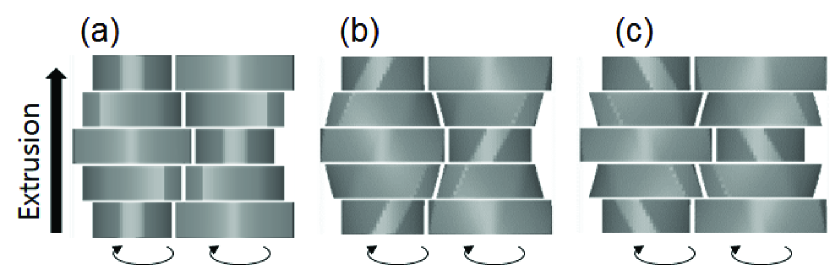
We discuss three kinds of the kneading blocks (KD). One is a conventional type shown in Fig. 1(a) called a forward kneading discs element (FKD) in which the five discs with non-pitched tips are arranged with a stagger angle between each two adjacent discs. The other geometries used in this study are the two different pitched-tip kneading discs (ptKD) element shown in Figs. 1(b) and (c). In Figs. 1(b) and (c), five discs are arranged with a forwarding disc-stagger angle, but the tips of each disc are twisted with respect to the screw axes. Depending on the direction of the tip angle, each disc can have a forward or backward pumping ability and thus modify the overall pumping ability of the kneading block. Corresponding to the tip angle directions, we call these pitched tips “forward tip” (Ft) or“backward tip” (Bt). Since in Fig. 1(b) the discs with Ft are combined with a forwarding disc-stagger angle, we call this geometry Fs-Ft ptKD, while in Fig. 1(c) the discs with Bt are combined with a forwarding disc-stagger angle, and so we call this geometry Fs-Bt ptKD. Along with this terminology, since FKD uses a non-pitched, neutral tip (Nt), it can also be called Fs-Nt ptKD.
The diameter of the barrel, , is set to 28 mm. All the discs composing the different kneading blocks have a diameter of 0.9893 and a width of 0.286. disc-stagger angles and pitched-tip angles are chosen so that the both inlet and outlet sections of the kneading blocks coincide as shown in Fig.1. disc-stagger angles for the three kneading blocks were respectively set to 45∘ for FKD, 40.715∘ for Fs-Ft ptKD, and 49.285∘ for Fs-Bt ptKD.
The pitched tips modify the channel geometry of the conventional KD as well as the pumping ability associated with the screw rotation. These effects result in a modification of the flow pattern and global mixing. In this paper, we investigate the relation between the geometry and the flow pattern, and discuss how the mixing characteristics are modified by this geometrical modification using the different pitched tips.
III Numerical simulation
III.1 Screw configuration
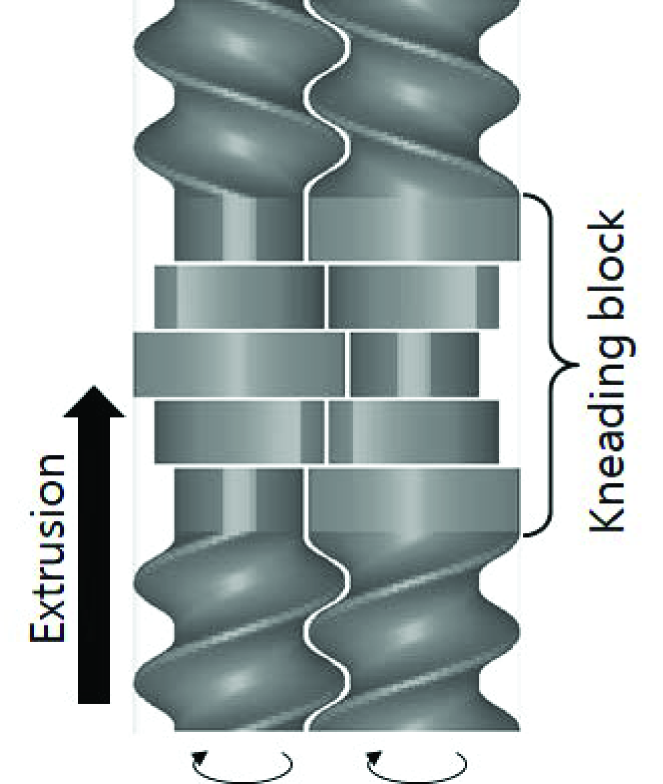
The flow of a polymer melt in the melt-mixing zone of a twin-screw extruder has been numerically solved to allow understanding the relation between the geometric structure of the kneading discs elements, the flow patterns, and the melt-mixing characteristics. The configuration of the screws is shown in Fig. 2. From the inlet, a forward conveying element, kneading block, and a backward conveying element are arranged. The length of the computational domain is . For the kneading block zone, we have set three types of pitched-tip kneading blocks of the described in the section “Geometric structures of pitched-tip kneading discs elements”.
III.2 Working fluid and boundary conditions
We focus on the situation where the material fully fills the channel. The Reynolds number is assumed to be much less than unity, so that inertial effects are neglected. The flow is assumed to be incompressible, and in a pseudo-steady state to the screw rotation, as has often been assumed in polymer flow in twin-screw extruders Ishikawa20003D ; Bravo2004Study ; Malik20053D ; Zhang2009Numerical ; Nakayama2011Meltmixing ; SarhangiFard2013Simulation ; Rathod2013Effect ; Hirata2014Effectiveness . With these assumptions, the governing equations become
| (1) | ||||
| (2) | ||||
| (3) |
where is the velocity, is the pressure, is the deviatoric stress, is the mass density, is the specific heat capacity, is the temperature, is the thermal conductivity, and is the strain-rate tensor in which the superscript T represents tensor transpose.
The fluid is assumed to be a viscous shear-thinning fluid that follows Cross–Arrhenius viscosity Cross1965Rheology ,
| (4) | ||||
| (5) | ||||
| (6) | ||||
| (7) |
whose parameters are obtained by fitting the shear viscosity of a polypropylene melt taken from Ref. Ishikawa20003D , and the values are , , Pas, and K. The mass density, specific heat capacity, and thermal conductivity are taken from Ref. Ishikawa20003D as well, and the values are kg/m3, J/(kgK), and W/(mK).
As operational conditions, the volume flow rate and the screw rotation speed are set to 10 cm3/s ( kg/h) and 200 rpm. The no-slip condition on the velocity at the barrel and screw surfaces is assumed. To circumvent the effects of the inlet and outlet boundary conditions, we set additional flight-less zones before and after the screw region of interest depicted in Fig. 2. The inlet and outlet boundary conditions are imposed at the ends of the flight-less zones. At the inlet plane, the uniform axial velocity was set to a value under the given volume flow rate. The pressure at the outlet boundary was fixed to be a constant value. The temperatures on the barrel surface and at the inlet boundary were set to be a constant value of 473.15 K. The natural boundary conditions for the temperature equation in the exit boundary plane and the screw surface were assigned. Physically, in the upstream flight-less zone, the flow develops before reaching the forward conveying element. The length of the flight-less screw zone was chosen to be 0.071 so that the flow in the kneading block zone does not change.
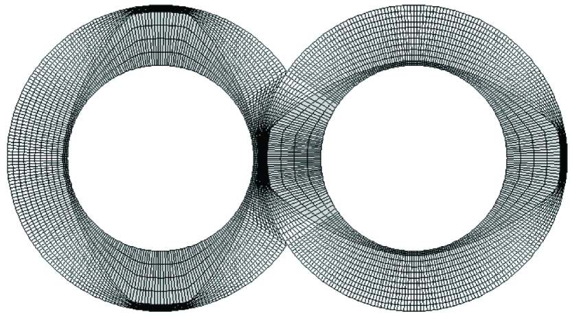
To obtain the pseudo-steady solution along the screw motion, the steady flow was solved at each three degree of the screw rotation. For each angle, the mesh conforming with the screw and barrel surfaces is generated. Fig. 3 shows an example of the meshing used in the numerical analysis.
III.3 Tracer statistics
The set of equations was discretized by the finite volume method and solved by SIMPLE method Versteeg2007Introduction using a commercial software, “R-FLOW” (R-flow Co., Ltd., Saitama, Japan). The trajectories of the passive tracers were calculated by integrating the solved velocity field. The set of tracer trajectories allows us to estimate the statistical distribution of the flow history, from which we can discuss the mixing characteristics in the local region of interest. This analysis was performed using the codes developed by the authors. The Lagrangian average of a quantity over the trajectory of th tracer is defined as
| (8) |
where and are the local residence time of the th tracer in the kneading block zone and the position of the th tracer, respectively, and is the Dirac delta distribution. The statistical distribution of characterizes the overall property of the fluid process in the melt-mixing zone, while the individual trajectories are connected to the local flow. Initially, about 2600 points were uniformly distributed in a certain section in front of the kneading block and were advected until they reached the end of the kneading block.
IV Results and discussion
IV.1 Pumping ability
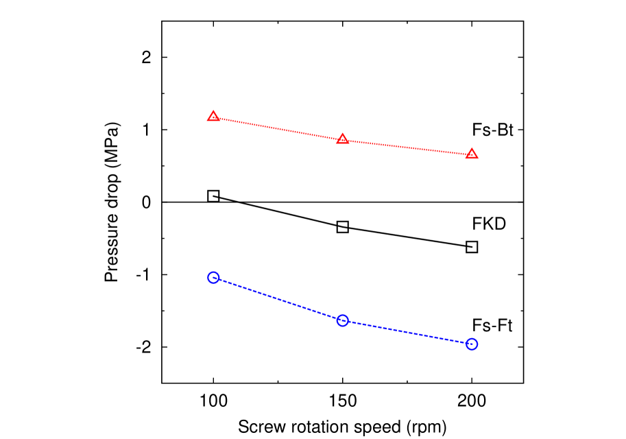
The geometry of a mixing element defines not only the channel geometry, but also the direction and the strength of the pressure flow under a flow rate and a screw rotation speed. The pressure flow combined with the drag flow by the screw rotation determines the flow pattern in the mixing zone. In ptKDs, the pumping ability is mainly determined by the combination of the disc-stagger angle and the tip angle. In Fig. 4, the average pressure drop across the kneading block as a function of the screw rotation speed under a flow rate of cm3/s is drawn for different kneading blocks. In the calculation of the average pressure drop, the pressure at the inlet and outlet sections of the kneading block is averaged spatially over the sections and temporally over one screw rotation. A positive/negative value of the pressure drop indicates that the pressure flow occurs on average in the forward/backward extrusion direction. Figure 4 clearly shows that the pumping ability increases in the order of Fs-Bt ptKD, FKD, and Fs-Ft ptKD, which reflects the forward and backward drags of the Ft and Bt, respectively. In particular, the Fs-Bt ptKD shows a positive pressure drop, indicating a negative pumping ability of Fs-Bt ptKD in contrast to the positive pumping abilities of Fs-Ft ptKD and FKD.
IV.2 Temperature profile
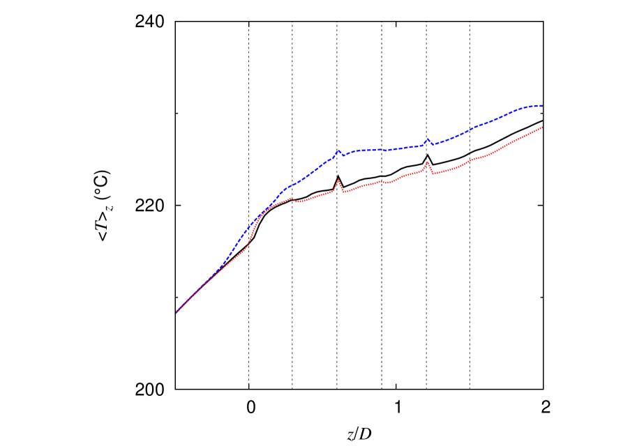
Fig. 5 shows the average temperature profile along the extrusion direction, where represents the average spatially over a section specified by an axial position of and temporally over one screw rotation. For the three different kneading blocks, the average temperature increases with the axial position, which is mainly due to the combined effects of the viscous heating and the mixing, but the variation of through the kneading block zone is rather small. Difference in for different geometries is at most 5 K. From this result, we assume that the temperature does not have a significant effect on the mixing ability.
IV.3 Flow pattern
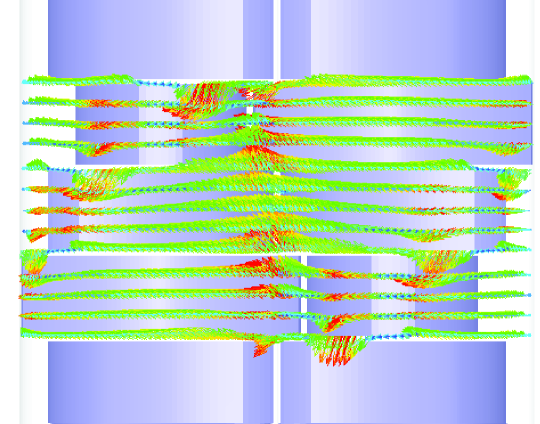
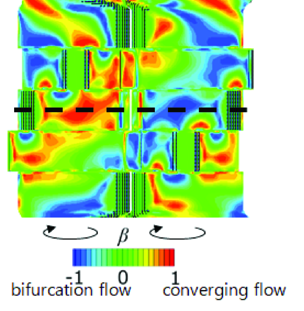
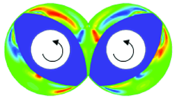
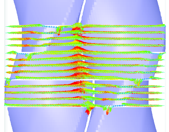
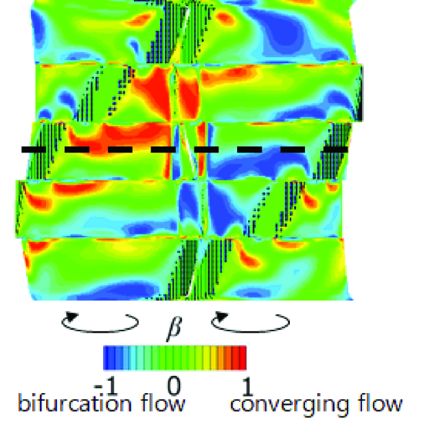
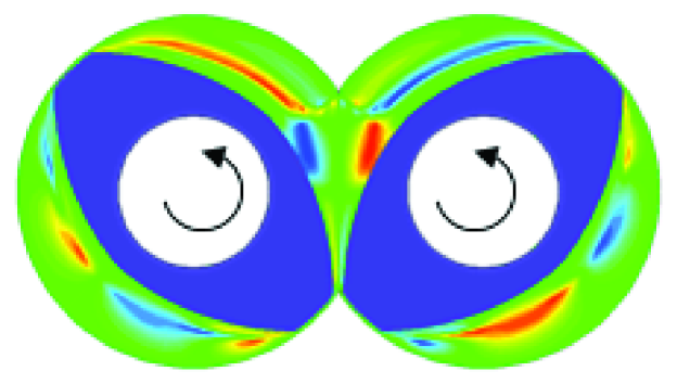
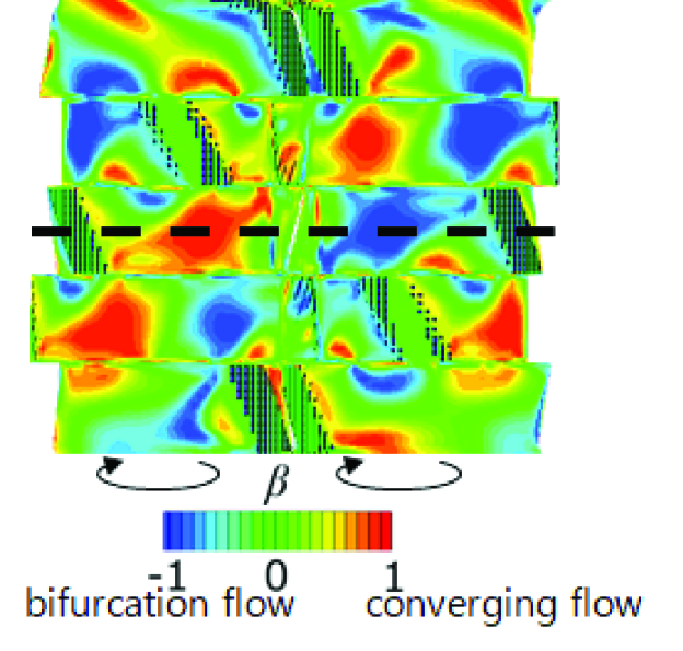
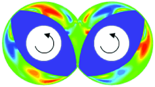
We discuss the flow patterns generated by different KDs. Figure 6(a) shows the velocity field in several axial sections in the kneading block zone of FKD, Fig. 6(b) shows the distribution of the strain-rate state, (Eq. (12)), at a mid-section between the barrel and screw surfaces in the kneading block zone of FKD. This section is specified by a mesh number in -direction shown in Fig. 3 and therefore reflects the shape of the screw surfaces. Fig. 6(c) shows distribution in the axial cross section indicated in Fig. 6(b). The distribution of the strain-rate state reflects the local flow pattern and therefore is useful for discussing the relation between the geometry and the flow pattern Nakayama2016Strain . A brief description of the strain-rate state is given in A.
Basically, as the screws rotate, each disc in the FKD induces a circumferential shear flow (Fig. 6(a)). The distribution of the shear flow is conveniently identified with the strain-rate state of (Figs. 6-8). Since the circumferential shear flow itself is almost unidirectional so that the flow reorientation and line folding rarely works. Then, at the front of the tips, some portion of the fluid elements is pushed out to the neighboring disc regions (Fig. 6(a)), which flow is observed as a bifurcating flow ( in Fig. 6(b)). In contrast, at the back of the tips, the inter-disc leakage flow from neighboring disc region and circumferential flow within the disc converge, which is observed as in Figs. 6(b) and (c). The bifurcating and converging flows cause the flow reorientation and line folding and stretching. Thus, the distribution of them gives an essential insight into the flow pattern and resulting mixing process. We note that the development of the bifurcating and converging flows is observed in the low-strain-rate regions far from the surfaces. This fact demonstrates that the distribution of the bifurcating and converging flows should be responsible for the global flow pattern driven by the geometry of FKD and its resulting mixing ability.
(a)
(b)
(c)
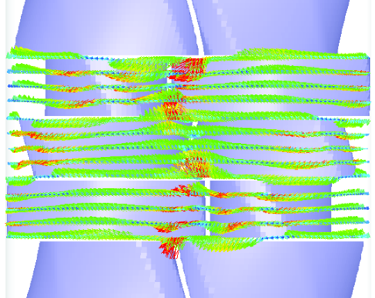
Next, we discuss how the pitched-tips modify the flow pattern in FKD. For Fs-Ft ptKD, the velocity field and the distribution of the strain-rate state are shown in Fig. 7. We observe in Fig. 7(a) that the bifurcating flow through the inter-disc openings is suppressed. In Figs. 7(b) and (c), the volume of the bifurcating and converging flows is reduced compared to FKD. Furthermore, the distribution of within individual disc regions is more asymmetric to the extrusion direction than that for FKD: within each disc region, the converging flow is localized in the downstream region while the bifurcating flow develops in the upstream region. At the same time, the volume of planar shear flow spreads over each disc. These results suggest that in Fs-Ft ptKD, the circumferential shear flow is prevailing, leading to less frequent flow reorientation and line stretching and folding.
(a)
(b)
(c)
For Fs-Bt ptKD, the velocity field and the distribution of the strain-rate state are shown in Fig. 8. In Fig. 8(a), inter-disc leakage flow as well as the circumferential flow in each disc are observed in a similar manner to FKD. Correspondingly, the distribution of the strain-rate state is similar to that for FKD. However, Figs. 8(b) and (c) clearly show that the volume of the non-planar flows becomes larger than that in FKD, indicating more frequent reorientation when fluid elements pass through the kneading block zone of Fs-Bt ptKD compared to FKD.
(a)
(b)
(c)
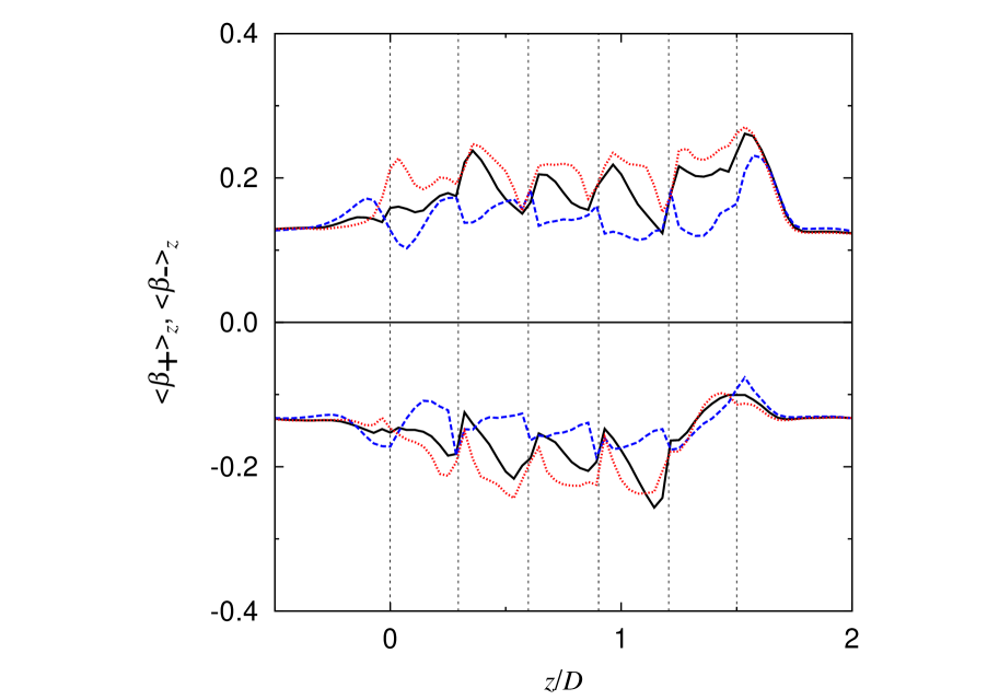
For a more quantitative evaluation of the non-planar flows, we compute the section-average of the strain-rate state as a function of the axial position. To separately evaluate the bifurcating and converging flows, we decompose into the following quantities,
| (9) |
where respectively represents the converging and bifurcating flows, and holds. In Fig. 9, the axial profile of is drawn. Since the flow pattern specific to kneading blocks develops at the inside discs out of the five discs shown in Fig. 1 that are sandwiched between two other discs, we focus on the variation of within the inner three discs region.
For FKD, the converging flow increases at the upstream side within individual disc regions while the bifurcating flow increases at the downstream side. This reflects the asymmetry of with respect to the extrusion direction within a disc observed in Fig. 6(b). For Fs-Ft ptKD, both the converging and bifurcating flows are substantially suppressed compared to FKD. This corresponds to the fact that in Fs-Ft ptKD the planar flow is prevailing and the occurrence of the non-planar flow is relatively suppressed, as observed in Figs. 7(b) and (c), indicating the bifurcating and converging flow from the circumferential flow occurs in limited regions. In contrast, for Fs-Bt ptKD, both the converging and bifurcating flows are enhanced compared to FKD, and their distributions are more extended over each disc, reflecting the observation of the enhanced occurrence of the non-planar flows in Figs. 8(b) and (c), indicating frequent occurrence of the flow reorientation by bifurcating and converging flow. This fact suggests that the flow pattern driven by Fs-Bt ptKD is more effective in distributive mixing than in FKD.
These results show that the geometrical modification by the pitched tips of the conventional FKD significantly affect the flow pattern in the low-strain-rate regions, which is effectively characterized by the distribution of the strain-rate state. The distribution of the converging and bifurcating flows is strongly associated with the channel geometry. We further discuss the effects of the variation of the flow pattern on the mixing and dispersive ability in the following sections.
IV.4 Residence time and mean stress during residence
The distributions of the local residence time and of the mean stress during residence in KD zone are commonly used to discuss the general characteristics of mixing and dispersive abilities in the kneading block zone. The distribution of the local residence time in the kneading block zone reflects the axial mixing ability of the kneading block, while the distribution of the mean stress during residence partly reflects the dispersive ability of the kneading block. The mean stress during the residence of the th tracer, , is calculated by Eq. (8) by inserting , which is a second-order invariant of the shear stress and measures the magnitude of the stress.
Basically, the residence time and Eq. (8) for any are defined for individual trajectories, and naturally they are correlated. Accordingly, simultaneous observation of the residence time and Eq. (8) rather than the separate observation of them can be more useful to understand the properties of the individual trajectories, the ensemble of which constitutes the overall mixing process. For this purpose, we consider the statistical distribution of the two quantities, , which is called a joint probability density function (joint PDF). The joint PDF reflects the correlation between the two quantities considered, and consequently characterizes the overall mixing process. A separate distribution like the residence time distribution, which has been often discussed, is obtained by integrating the other variable of the joint PDF as .
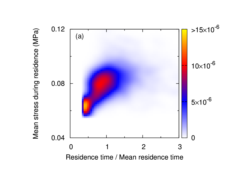
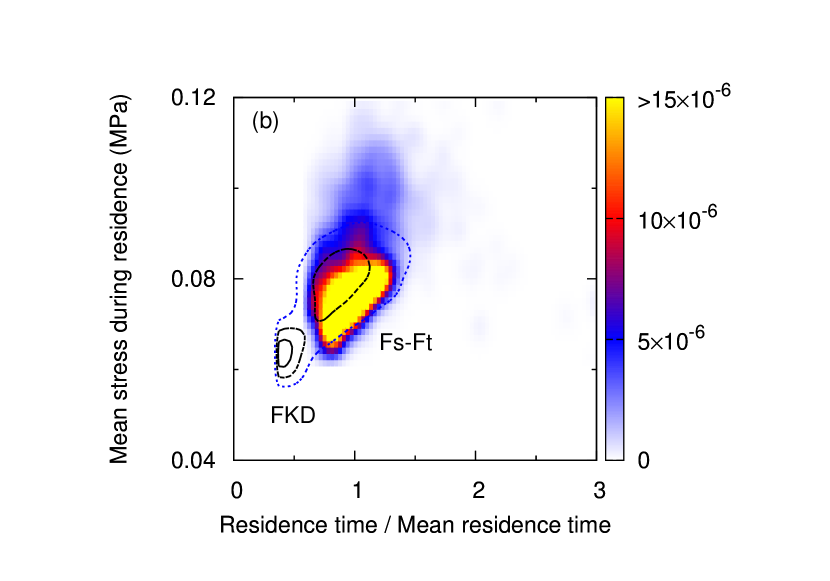
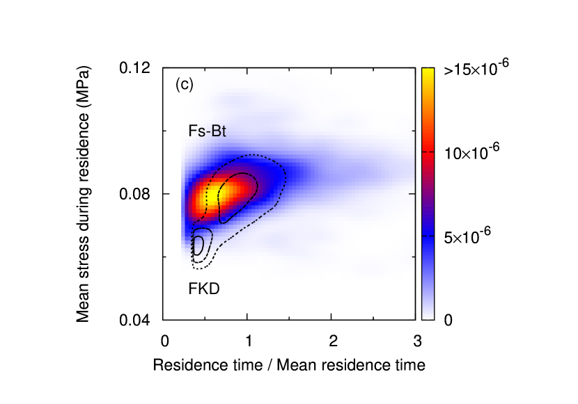
Figure 10 shows the joint PDF of the residence time and in the kneading block zone under a flow rate of 10 cm3/s and a screw rotation speed of 200 rpm. In the case of the FKD shown in Fig. 10(a), when only looking at the residence time distribution, the normalized residence time has a wide distribution between 0.3 to 1.6, indicating a high capability of axial mixing. However, the joint PDF of and for FKD has two peaks, suggesting that the trajectories are classified into two different groups which are not mutually mixed. One group of the shorter residence time takes smaller but another group of the longer residence time takes larger . This fact indicates that although the residence time fluctuation in FKD is broad, the overall mixing by FKD can have a large inhomogeneity.
In contrast, for Fs-Ft and Fs-Bt ptKDs, the joint PDFs of the residence time and are unimodal (Figs. 10(b) and (c)), suggesting that the segregation of the trajectories observed for FKD is suppressed. Quantitatively, the fluctuation of the residence time and the level of are different for Fs-Ft and Fs-Bt ptKDs. For Fs-Ft ptKD, while the mean stress during residence remains almost at the same level as for FKD, the normalized residence time lies between 0.7 to 1.3, so that the fluctuation of the residence time is reduced. For Fs-Bt ptKD, with the same level of residence time fluctuation as observed for FKD, a higher level of the mean stress during residence is achieved. These facts demonstrate that irrespective of the tip angle, the pitched tips on FKD are effective at reducing the inhomogeneity of the trajectories, and that the mixing characteristics can be tunable by the pitched-tip angle as well.
IV.5 Quantification of mixing: Finite-time Lyapunov exponent
Although the residence time distribution has been often used to assess the mixing ability, it only measures the residence time of an individual trajectory, so that it is not a direct measure of the mixing process. In order for mixing to occur, the disappearance of positional correlation with time is a necessary process. For the nonrecurrent dynamics occurring in extrusion, this process can be quantified by the finite-time Lyapunov exponent (FTLE). The FTLE measures the exponential growth rate over a finite time interval of the distance between two initially nearby points, and is defined as
| (10) |
where is the relative position vector between the two points, is the initial time, and is the time interval. When is positive, the disappearance of positional correlation is faster for larger , implying a high mixing ability. But zero or negative indicates the maintenance of the positional correlation, implying a poor mixing ability. It is supposed that The line stretching by elongational flow and reorientation flows are supposed to cause a positive FTLE, whereas unidirectional planar flow is less likely to cause a large FTLE.
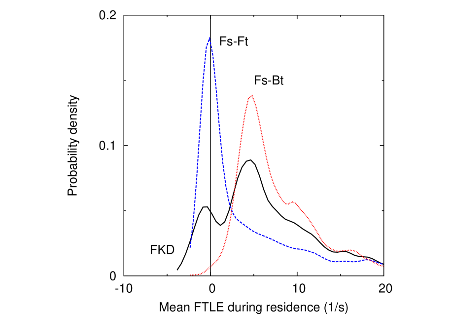
Figure 11 shows the PDF of the time-averaged FTLE during residence in the kneading block zone, , under a flow rate of 10 cm3/s and a screw rotation speed of 200 rpm. The time-averaged FTLE during residence is calculated for each trajectory specified by with Eq. (8) by inserting Eq. (10) into . The individual characterizes the mixing ability along the th trajectory. In order to discuss the overall mixing ability of the kneading block zone, PDF of is calculated. For FKD, we observe a bimodal distribution of , which is composed of a larger fraction of positive FTLE and a smaller fraction of negative FTLE. The large fraction of the trajectories with positive FTLE basically indicates that there is some level of good mixing ability of FKD. However, at the same time, the finite fraction of negative FTLE clearly indicates the existence of some portion with poor mixing ability, which should lead to a large inhomogeneity of the mixing process, and can be a bottleneck in the overall mixing process.
Figures 12 and 13 show typical pathlines of two tracers of initially nearby locations: Fig. 12 is for a case with a negative FTLE and Fig. 13 is for a case with a positive FTLE. In the case with a negative FTLE, the initially nearby two tracers remain close to each other while passing through the kneading block zone. In contrast, for the case with a positive FTLE, the two initially nearby tracers start to move apart at a certain point, and after that they follow completely uncorrelated trajectories.
The trajectories with large positive FTLE are found to move back and forth over discs more frequently than those with negative FTLE (Fig. 13). The back and forth motion between discs is associated with the bifurcating and converging flows observed in Fig.6.
For Fs-Ft and Fs-Bt ptKDs, although the levels of the FTLE are different, the distributions of are almost unimodal. For Fs-Ft ptKD, although the average value of over the ensemble of the trajectories is positive, a large fraction of the trajectories takes a value around zero, indicating that the mixing ability is rather suppressed compared to FKD. For Fs-Bt ptKD, the fraction of negative values of almost vanishes. The average over the trajectory ensemble takes a larger value than that for FKD, suggesting an enhanced mixing ability of Fs-Bt ptKD.
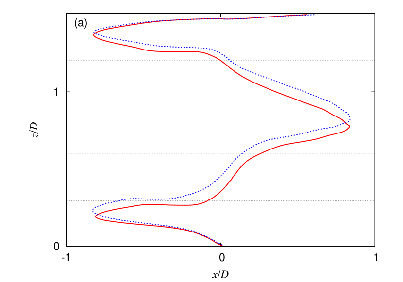

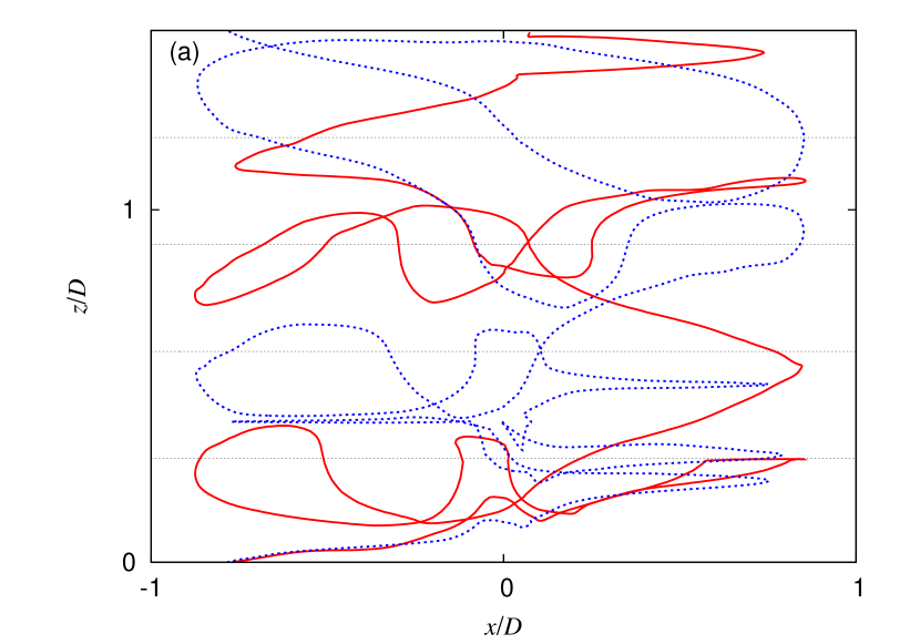

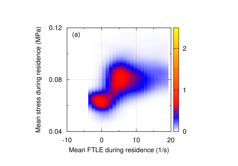
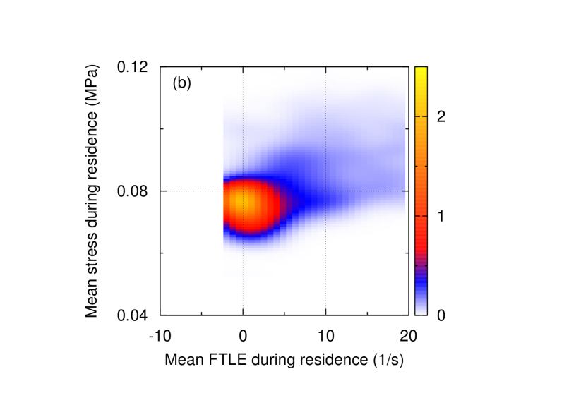
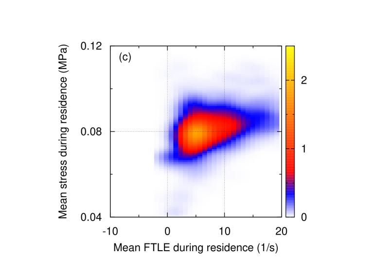
Figure 14 shows the joint PDF of and under a flow rate of 10 cm3/s and a screw rotation speed of 200 rpm. Figure 14(a), for FKD, clearly shows that the trajectories with lower mean stress take negative or positive but small values of FTLE, suggesting that the poor mixing ability of this group causes a large inhomogeneity in the overall mixing by FKD. For Fs-Ft ptKD (Fig. 14(b)) and Fs-Bt ptKD (Fig. 14(c)), the distributions of and are unimodal, so that the mixing processes in these ptKDs are qualitatively rather homogeneous. These results reveal the suppressed mixing in Fs-Ft ptKD and the enhanced mixing in Fs-Bt ptKD compared to FKD. The distribution of the FTLE turns out to be useful to quantify the mixing characteristics of different mixing elements.
IV.6 Quantification of dispersive mixing efficiency
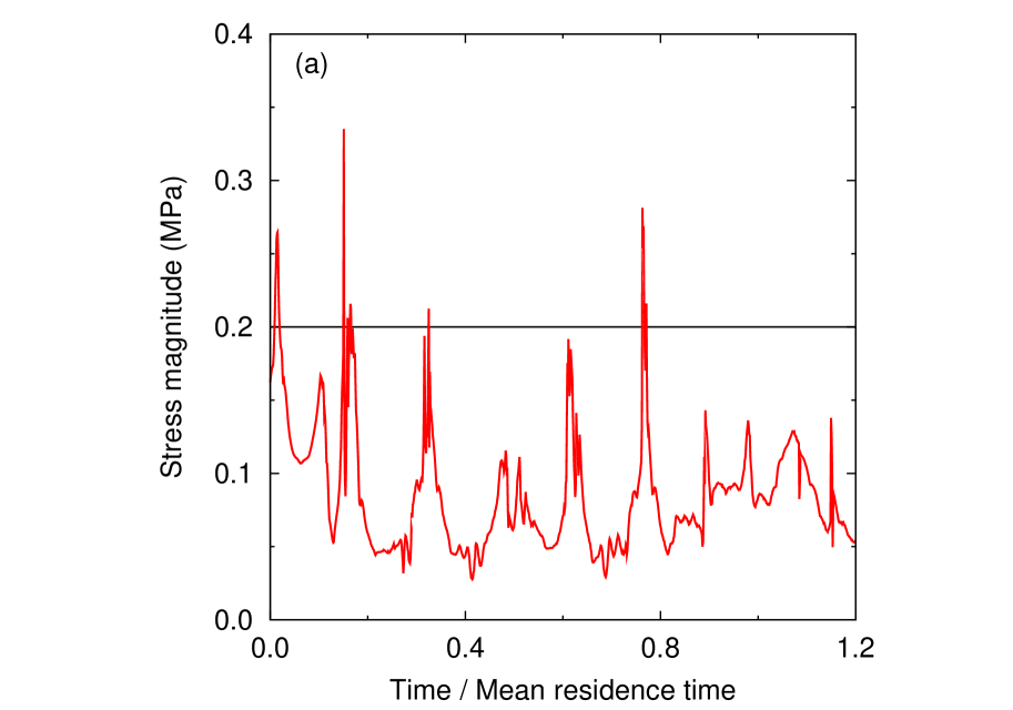
Dispersive mixing is mainly promoted when a fluid element passes through the high-stress regions. In twin-screw mixers, the highest level of the stress is achieved in the small-gap regions, including the tip–barrel clearance and the inter-meshing region, independent of the disc-stagger angle and the pitched-tip angle. Figure 15(a) shows a typical time series of the stress magnitude on a tracer. The impulsive peaks in Fig. 15(a) indicate that the tracer passes through the high-stress region. Although the passage time of the high-stress regions is highly limited in the whole residence time in the kneading block zone, it is a determining factor for dispersion efficiency. Since the passage of the fluid to the high-stress regions depends on the flow pattern in the low-stress regions, it should be directly affected by the geometry of the mixing elements. To quantify the dispersion efficiencies of the different KDs, we computed the passage time in the high-stress regions.
In order to define the high-stress regions, we introduce a threshold value, , for the stress magnitude, which value was arbitrarily set to 0.2 MPa, indicated in Fig. 15(a), to cover both the tip–barrel clearance and the inter-meshing region. Based on this, the passage time in the high-stress regions for the th tracer, , is calculated as
| (11) |
where represents Heaviside step function. The is the summation of the time when exceeds the threshold for the th tracer.
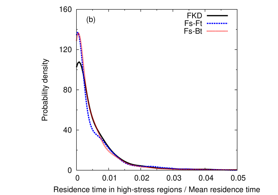
Figure 15(b) shows the PDF of under a flow rate of 10 cm3/s and a screw rotation speed of 200 rpm. For both Fs-Ft and Fs-Bt ptKDs, the fraction of the vanishing passage time in the high-stress regions is slightly larger than for FKD. However, the distribution of the finite time passage of the high-stress regions is almost similar for FKD, Fs-Ft and Fs-Bt ptKDs, suggesting that the dispersion efficiencies for Fs-Ft and Fs-Bt ptKDs are at the same level as for FKD.
V Conclusions
For mixing elements in twin-screw extrusion, we investigated the effects of a geometrical modification by pitched tips of the conventional forward kneading block (FKD) on the flow pattern and the mixing characteristics, employing numerical simulations of the three-dimensional melt flow. Based on the FKD geometry, two different pitched tips, forward and backward pitched-tip angles, were considered, and these two pitched-tip kneading block (ptKD) are respectively called Fs-Ft and Fs-Bt ptKDs. In flow driven by FKD, we found that the trajectories were composed of two qualitatively different groups: poorly mixing ones and highly mixing ones. The poorly mixing group causes a large inhomogeneity of the overall mixing in FKD. In contrast, in flows driven by either ptKD, the mixing characteristics are found to be qualitatively homogeneous.
The mixing characteristics depend on the geometry of the ptKD. Fs-Ft ptKD has a suppressed level of mixing compared to FKD, but has the same level of dispersion ability as FKD. Fs-Bt ptKD has a highly enhanced mixing ability as well as dispersion ability. Our results revealed that the geometrical modification by the pitched tips of the conventional KD is effective at improving, as well as tuning, the mixing characteristics of KD.
In the investigation of the mixing characteristics in this paper, we employed different approaches, including the strain-rate state distribution, the distribution of the finite-time Lyapunov exponent (FTLE), and the passage time in the high-stress region, in addition to the conventional approaches like the residence time distribution. These approaches were found to be useful for clarifying the relations between the channel geometry, the flow pattern, and the mixing characteristics. Understanding the relation between the channel geometry and the flow pattern behind different mixing characteristics of different mixing elements is an essential issue in the optimization and the development of mixing processes. In this direction, our approaches can be applied to other mixing devices, including twin-screw ones as well as single screw ones.
Acknowledgments
The numerical calculations were partly carried out using the computer facilities at the Research Institute for Information Technology at Kyushu University. This work has been supported by Grants-in-Aid for Scientific Research (JSPS KAKENHI) under Grants Nos. JP26400433, and JP15H04175. Financial support from Hosokawa Powder Technology Foundation is also greatfully acknowledged.
Appendix A Strain-rate state and local flow pattern
The local flow pattern is closely related to the distribution of the strain-rate state. For instance, the biaxial elongational flow is associated with the bifurcation of the flow, while the uniaxial elongational (biaxial compression) flow is associated with the convergence of the flow. Since the flow pattern is mainly controlled by the channel geometry, the spatial distribution of the strain-rate state is useful for understanding the relation between the geometry and the structure of the local flow pattern Nakayama2016Strain . The strain-rate state distribution has also been used to discuss the elongational flow distribution in turbulence Lund1994Improved ; Toonder1996Criterion .
We here briefly describe the quantification of the strain-rate state. The strain-rate state is evaluated with the following dimensionless scalar,
| (12) |
which take a value in . is an invariant of since both and are invariants of . For an arbitrary uniaxial elongational flow, takes a positive value, while for an arbitrary biaxial elongational flow, takes a negative value. Special cases are for equibiaxial compression (uniaxial elongational) flow, for equibiaxial elongational flow, and for planar shear flow. Therefore, a positive value of indicates a converging flow, while a negative value of indicates a bifurcating flow.
Literature Cited
- (1) Tadmor Z, Gogos CG. Principles of Polymer Processing. New Jersey: Wiley-Interscience, 2nd ed. 2006.
- (2) Kohlgruber K. Co-Rotating Twin Screw Extruder. Munich: Hanser. 2007.
- (3) White JL, Kim EK. Twin Screw Extrusion Technology and Principles. Munich: Hanser. 2010.
- (4) Aguilera JM, Barbosa-Canovas GV, Simpson R, Welti-Chanes J, Bermudez-Aguirre D, eds. Food Engineering Interfaces. New York: Springer. 2011.
- (5) Rauwendaal C. Polymer Extrusion. Munich: Hanser, 5th ed. 2014.
- (6) Christiano JP. SPE Antec Tech Papers. 1993;39:3386.
- (7) Lawal A, Kalyon DM. Mechanisms of mixing in single and co-rotating twin screw extruders. Polym Eng Sci. 1995;35(17):1325–1338.
- (8) Lawal A, Kalyon DM. Simulation of intensity of segregation distributions using three-dimensional fem analysis: Application to corotating twin screw extrusion processing. J Appl Polym Sci. 1995;58(9):1501–1507.
- (9) Cheng H, Manas-Zloczower I. Study of mixing efficiency in kneading discs of co-rotating twin-screw extruders. Polym Eng Sci. 1997;37(6):1082–1090.
- (10) Carneiro OS, Caldeira G, Covas JA. Flow patterns in twin-screw extruders. J Mater Process Tech. 1999;92-93:309–315.
- (11) Shearer G, Tzoganakis C. Analysis of mixing during melt-melt blending in twin screw extruders using reactive polymer tracers. Polym Eng Sci. 1999;39(9):1584–1596.
- (12) Alsteens B, Legat V, Avalosse T. Parametric Study of the Mixing Efficiency in a Kneading Block Section of a Twin-screw Extruder. Intern Polym Process. 2004;19:207–217.
- (13) Jaffer SA, Bravo VL, Wood PE, Hrymak AN, Wright JD. Experimental validation of numerical simulations of the kneading disc section in a twin screw extruder. Polym Eng Sci. 2000;40(4):892–901.
- (14) Bravo VL, Hrymak AN, Wright JD. Numerical simulation of pressure and velocity profiles in kneading elements of a co-rotating twin screw extruder. Polym Eng Sci. 2000;40(2):525–541.
- (15) Shearer G, Tzoganakis C. The effects of kneading block design and operating conditions on distributive mixing in twin screw extruders. Polym Eng Sci. 2000;40(5):1095–1106.
- (16) Shearer G, Tzoganakis C. Distributive mixing profiles for co-rotating twin-screw extruders. Adv Polym Technol. 2001;20(3):169–190.
- (17) Shearer G, Tzoganakis C. Relationship between local residence time and distributive mixing in sections of a twin-screw extruder. Polym Eng Sci. 2001;41(12):2206–2215.
- (18) Nakayama Y, Takeda E, Shigeishi T, Tomiyama H, Kajiwara T. Melt-mixing by novel pitched-tip kneading disks in a co-rotating twin-screw extruder. Chem Eng Sci. 2011;66(1):103–110.
- (19) Kubik P, Vlcek J, Tzoganakis C, Miller L. Method of analyzing and quantifying the performance of mixing sections. Polym Eng Sci. 2012;52(6):1232–1240.
- (20) Hirata K, Ishida H, Hiragohri M, Nakayama Y, Kajiwara T. Effectiveness of a backward mixing screw element for glass fiber dispersion in a twin-screw extruder. Polym Eng Sci. 2014;54(9):2005–2012.
- (21) Zhang XM, Feng LF, Chen WX, Hu GH. Numerical simulation and experimental validation of mixing performance of kneading discs in a twin screw extruder. Polym Eng Sci. 2009;49(9):1772–1783.
- (22) Sarhangi Fard A, Anderson PD. Simulation of distributive mixing inside mixing elements of co-rotating twin-screw extruders. Comput Fluids. 2013;87:79–91.
- (23) Yamada S, Fukutani K, Yamaguchi K, Funahashi H, Ebata K, Uematsu H, Tanoue S. Dispersive Mixing Performance Evaluation of Special Rotor Segments in an Intermeshing Co-Rotating Twin-Screw Extruder by Using Weighted Probability Distributions. Intern Polym Process. 2015;30(4):451–459.
- (24) Nakayama Y, Kajiwara T, Masaki T. Strain mode of general flow: Characterization and implications for flow pattern structures. AIChE J. 2016;62(7):2563–2569.
- (25) Nakayama Y, Nishihira N, Kajiwara T, Tomiyama H, Takeuchi T, Kimura K. Effects of pitched tips of novel kneading disks on melt mixing in twin-screw extrusion. Nihon Reoroji Gakkaishi (Journal of the Society of Rheology, Japan). 2016;44(5):281–288.
- (26) McCullough TW, Hilton BT. SPE Antec Tech Papers. 1993;39:3372.
- (27) Ishikawa T, Kihara SI, Funatsu K. 3-D numerical simulations of nonisothermal flow in co-rotating twin screw extruders. Polym Eng Sci. 2000;40(2):357–364.
- (28) Bravo VL, Hrymak AN, Wright JD. Study of particle trajectories, residence times and flow behavior in kneading discs of intermeshing co-rotating twin-screw extruders. Polym Eng Sci. 2004;44(4):779–793.
- (29) Malik M, Kalyon DM. 3D Finite Element Simulation of Processing of Generalized Newtonian Fluids in Counter-rotating and Tangential TSE and Die Combination. Intern Polym Process. 2005;20(4):398–409.
- (30) Rathod ML, Kokini JL. Effect of mixer geometry and operating conditions on mixing efficiency of a non-Newtonian fluid in a twin screw mixer. J Food Eng. 2013;118(3):256–265.
- (31) Cross MM. Rheology of non-Newtonian fluids: A new flow equation for pseudoplastic systems. J Colloid Sci. 1965;20(5):417–437.
- (32) Booy ML. Geometry of fully wiped twin-screw equipment. Polym Eng Sci. 1978;18(12):973–984.
- (33) Versteeg H, Malalasekera W. An Introduction to Computational Fluid Dynamics: The Finite Volume Method (2nd Edition). Harlow, England: Prentice Hall, 2nd ed. 2007.
- (34) Lund TS, Rogers MM. An improved measure of strain state probability in turbulent flows. Phys Fluids. 1994;6(5):1838–1847.
- (35) den Toonder JMJ, Kuiken GDC, Nieuwstadt FTM. A criterion for identifying strong flow regions in turbulence. Euro J Mech B. 1996;15:735–753.