Geometrically asymmetric optical cavity for strong atom-photon coupling
Abstract
Optical cavities are widely used to enhance the interaction between atoms and light. Typical designs using a geometrically symmetric structure in the near-concentric regime face a tradeoff between mechanical stability and high single-atom cooperativity. To overcome this limitation, we design and implement a geometrically asymmetric standing-wave cavity. This structure, with mirrors of very different radii of curvature, allows strong atom-light coupling while exhibiting good stability against misalignment. We observe effective cooperativities ranging from to by shifting the location of the atoms in the cavity mode. By loading 171Yb atoms directly from a mirror magneto-optical trap into a one-dimensional optical lattice along the cavity mode, we produce atomic ensembles with collective cooperativities up to . This system opens a way to preparing spin squeezing for an optical lattice clock and to accessing a range of nonclassical collective states.
I Introduction
The interaction between atoms and electromagnetic fields has been studied for more than a century, and has provided many important insights. For an atom at rest, the spectral profile of a single transition is a Lorentzian function. When the atom is so strongly coupled to an electromagnetic mode that its absorption and dispersion appreciably change the mode characteristics, two coupled normal modes with a mixed atom-field character emerge (vacuum Rabi splitting). The strong coupling of an atom to an optical-resonator mode opened the field of cavity quantum electrodynamics (QED) in the optical domain, both for individual atoms Thompson et al. (1992); Münstermann et al. (1999); Nguyen et al. (2017); Reiserer and Rempe (2015) and for atomic ensembles Miller et al. (2005); Tanji-Suzuki et al. (2011a); Chen et al. (2011); Haas et al. (2014); Gupta et al. (2007); Casabone et al. (2013). Notable results include the observation of single-atom vacuum Rabi splitting Thompson et al. (1992) and the associated optical nonlinearity Birnbaum et al. (2005), a single-photon transistor Chen et al. (2013); Hacker et al. (2016); Sun et al. (2018), a photon-atom quantum gate Reiserer et al. (2014), polarization-dependent directional spontaneous photon emission Mitsch et al. (2014), light-induced spin squeezing Hosten et al. (2016); Cox et al. (2016); Leroux et al. (2010); Béguin et al. (2014), preparation of entangled many-atom spin states McConnell et al. (2015); Haas et al. (2014), and photon-induced entanglement between distant particles Northup and Blatt (2014).
The most common structure used in cavity QED experiments is a Fabry-Perot (FP) cavity consisting of two spherical mirrors with equal radii of curvature (ROCs) Miller et al. (2005); Tanji-Suzuki et al. (2011a); Chen et al. (2011); Haas et al. (2014); Gupta et al. (2007). For confocal and shorter cavities, this configuration exhibits good mechanical stability of the optical mode. However, when it comes to increasing the single-atom cooperativity , the structure has certain constraints: to achieve a small mode waist with commercially available super-polished mirrors of centimeter-scale ROCs, the two mirrors need to be very far from each other (near-concentric cavity) Stute et al. (2012), or very close to each other (near-planar cavity) Miller et al. (2005). The near-concentric cavity is very sensitive to alignment errors, while the near-planar cavity offers little optical access. To overcome these difficulties, we instead implemented a geometrically asymmetric cavity, which offers good optical access and a very small mode waist at reasonable mechanical stability. This paper describes the concept and experimental realization of such an asymmetric cavity with high . We observe single-atom cooperativity up to , and collective cooperativity up to with trapped-atom lifetime exceeding several seconds.
II Concept of asymmetric cavity
Cavity QED is a gateway for manipulating single atoms and atomic ensembles using light Kimble (1998); Tanji-Suzuki et al. (2011b). The all-important parameter is the single-atom cooperativity at an antinode , given by
| (1) |
for a standing wave cavity Tanji-Suzuki et al. (2011b). This parameter is a dimensionless constant in cavity QED that describes the strength of atom-light interaction, where is the coupling constant (single-photon Rabi frequency) between an atom and a photon, is the decay rate of a photon in the cavity, is the decay rate of the atomic excited state, is the finesse of the cavity, is the wavenumber, and is the intensity radius of the cavity mode. An important realization in cavity QED is that the ratio of the coupling constant squared and the product of decay rates is purely geometric. Therefore, designing a cavity with , useful for obtaining highly entangled states using light Chen et al. (2015), is reduced to designing a cavity with small beam size and high finesse .
The geometrical relation between the ROCs and positions of two mirrors, and the resulting shape of the cavity mode are well known (e.g. Siegman (1986)). If one uses more than two mirrors, a waist size smaller than that with a conventional two-mirror cavity can be realized Cox et al. (2018), but here we concentrate on a cavity with two mirrors, because it benefits from a simpler mechanical structure and lower optical loss. In the general case, the waist size for a two-mirror cavity is given by Siegman (1986)
| (2) |
where , denote the ROC of the two mirrors, and is the distance between the two mirrors.
In the case of a symmetric cavity ( and thus ), this expression simplifies to , leading to two possible cavity configurations with small : (i) when the two mirrors are very close to each other, , and (ii) when the two mirrors are in a near-concentric configuration, .
The first configuration has good mechanical stability due to a large optical axis length, given by the distance between the centers of curvature of the two mirrors. This is a good configuration for having very high cooperativity, and has been used in many experiments, particularly with single atoms Thompson et al. (1992); Münstermann et al. (1999); Birnbaum et al. (2005); Miller et al. (2005), though the optical access for loading and manipulating atoms is very limited. With additional technical effort, such as a movable magnetic trap Gupta et al. (2007); Colombe et al. (2007); Fortier et al. (2007), it is possible to load large atomic ensembles even into very short cavities.
The near-concentric configuration, on the other hand, offers excellent optical access for loading atoms directly into the cavity mode from a magneto-optical trap (MOT) or any other type of trap. However, in this case, the length of the optical axis is short: . For example, to obtain m with mm, the cavity has m for 556 nm light. This causes difficulties in obtaining and maintaining alignment of the cavity, as well as poor mechanical stability. In this case, higher-order transverse modes are close to the fundamental mode in frequency, which can be problematic for experiments aiming to couple atoms to a single cavity mode. Nevertheless, this type of cavity is used for ions to keep the mirror surfaces far away from the trapped particles Casabone et al. (2013). Some cavities even utilize mirrors with aspheric structure to attain the large numerical aperture required for focusing the beam tightly Durak et al. (2014); Nguyen et al. (2018).
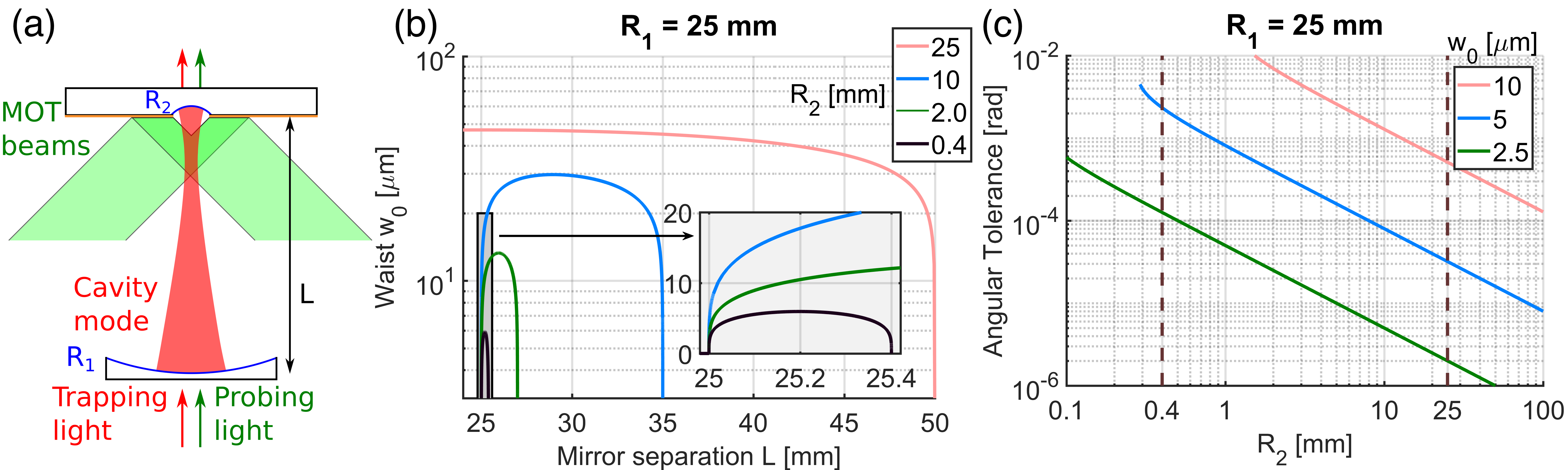
Next, we consider an asymmetric cavity with [see Fig. 1(a)]. In this case, there are two separate stability regions, one with and the other with . Figure 1(b) shows the waist size in the long stability region with . As shrinks, so does the maximum mode waist . When and are fixed, larger gives a larger angular tolerance , which is the sensitivity of the optical axis alignment to any tilt in the cavity mounting hardware. When a target is set and is varied, smaller gives larger angular tolerance , as shown in Fig. 1(c). This motivates the construction of an asymmetric cavity consisting of a standard super-polished mirror of mm and a micromirror of m, which is manufactured by ablation with a CO2 laser pulse Hunger et al. (2010), to simultaneously achieve high cooperativity, large distance between the two mirrors, and large angular tolerance . Compared to a symmetric cavity with mm, this setup is 60 times more stable with respect to angular misalignment [see Fig. 1(c)].
III Cavity properties
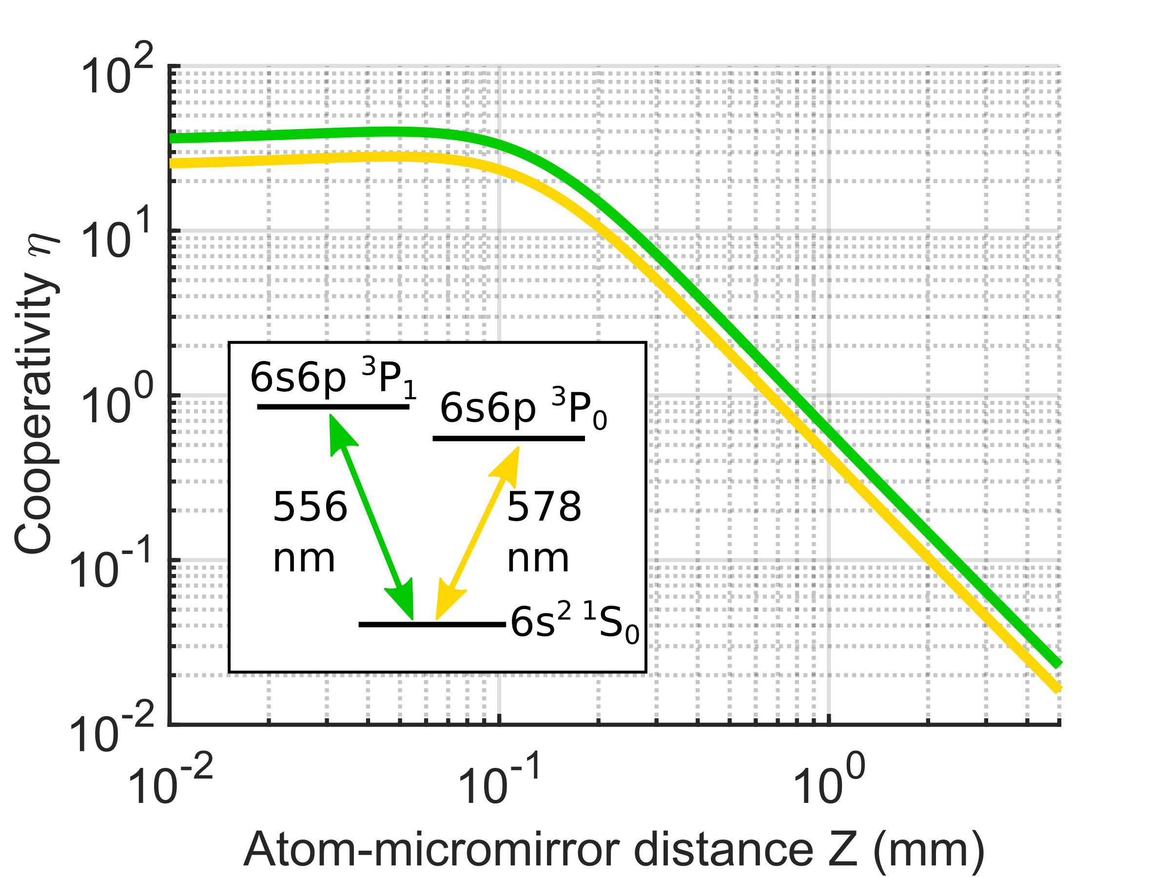
We built an asymmetric cavity with a slightly elliptical micromirror ( m, m Braverman (2018)) on a flat substrate and a standard super-polished mirror ( mm, see Appendixes for the mechanical details and the procedure of construction). The mirrors have high reflectivity coatings for 556 nm and 759 nm light at normal incidence. The mirrors also reflect 99 % of the 399 nm and 556 nm light at 45∘ angle of incidence to enable the operation of a mirror MOT with ytterbium, as shown in Fig. 1(a). Prior to fixing the mirror distance, the finesse is measured for different separations between the two mirrors. A constant is observed in the region of mm, and it decreases at larger , which may be caused by extra loss due to the large mode size on the nonspherical micromirror Benedikter et al. (2015). The inter-mirror distance is fixed at mm, which is calibrated by the disappearance of the cavity mode when and a known shift by a micrometer stage. Note that this distance is different from mm derived from the measured free spectral range (FSR) of 5970.04(4) MHz, which potentially implies the breakdown of the simple relation between the FSR and cavity length at small waist size, where the paraxial approximation no longer holds (see Appendix B for more discussion). The expected cooperativity for different atom position , defined as the distance of the atoms from the micromirror, is calculated based on the mode geometry and . The single-atom cooperativity and other QED parameters are summarized in Table 1 and Fig. 2. In addition to the transition at 556 nm, the cavity also has a high finesse for the clock transition at 578 nm. The single-atom cooperativity for 556 nm light can be tuned from the maximum of 40 to less than 0.1 by changing the position of the atoms by a few millimeters, as shown in Fig. 2.
| wavelength | 556 nm | 578 nm | 759 nm |
|---|---|---|---|
| 60(2) ppm | 80(5) ppm | 1000(50) ppm | |
| 390(10) ppm | 580(20) ppm | 1000(50) ppm | |
| 184(1) kHz | 7.0(2) mHz | - | |
| 426(2) kHz | 628(4) kHz | 1.90(4) MHz | |
| 885(5) kHz | 176(1) Hz | - | |
| 40.0 | 28.2 | - | |
| 4.60 m | 4.70 m | 5.38 m |
IV Atom trapping in the cavity mode
To measure the single-atom cooperativity with atoms, a mirror MOT Reichel et al. (1999) is operated with 171Yb [see also Fig. 1(a)]. The atoms are first loaded into a two-color MOT Kawasaki et al. (2015). Subsequently, the 399 nm cooling light on the transition is turned off, the detuning of the 556 nm MOT light is reduced from MHz to kHz (the linewidth of the transition is kHz), and a bias magnetic field is added to move the atoms to the desired location along the cavity axis. Typically around 171Yb atoms are trapped in the MOT by 556 nm light at a temperature of 15 K, with a rms cloud radius of 60 m along the vertical cavity axis.
To trap the atoms in the cavity mode, a one-dimensional optical lattice near the magic wavelength of 759 nm for the clock transition is generated inside the cavity. With a typical circulating power of 1.2 W, the trap depth at a distance of mm from the micromirror is MHz, with trapping frequencies 142(3) kHz axially and 1.39(10) kHz radially. To load the atoms into the optical lattice, the detuning of the 556 nm MOT light is increased from kHz to kHz, and the intensity per beam is lowered to 0.05 mW/cm2 (the saturation intensity of the transition is 0.14 mW/cm2) for 20 ms before the MOT light is extinguished. The lifetime of the atoms in the optical lattice is typically a few seconds, limited by intensity noise in the lattice, and approaching the limit set by background gas collisions.
V Single-atom and collective cooperativity measurement
A cavity-QED system with atoms in the cavity mode is typically characterized by the single-atom cooperativity and the collective cooperativity , where is the atom number. The single-atom cooperativity determines the strength of the interaction between atoms and light, while the collective cooperativity sets some limits for the manipulation of the quantum system, such as the amount of attainable spin squeezing (e.g., Schleier-Smith et al. (2010); Chen et al. (2014)). This is because determines the ratio of useful collective light scattering by the ensemble into the cavity relative to the scattering of light into free space, which results in decoherence Tanji-Suzuki et al. (2011b).
V.1 Single-atom cooperativity
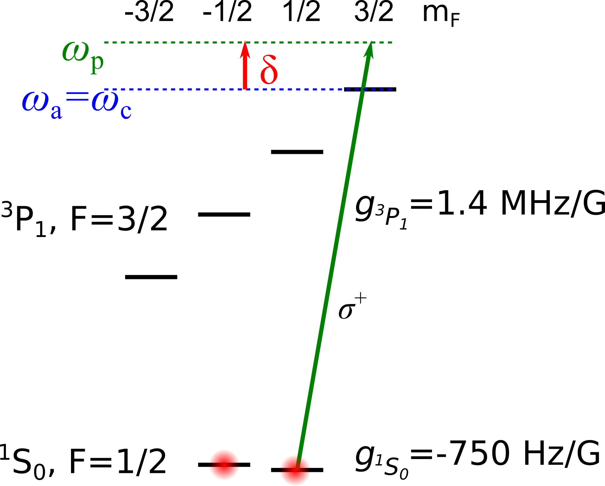
The single-atom cooperativity can be experimentally determined as the effective single-atom cooperativity by measuring the atomic phase shift induced by off-resonant probing light Tanji-Suzuki et al. (2011b). The measured value of equals , assuming a uniform distribution of atoms along the cavity mode Hu et al. (2015). To perform the measurement, atoms are optically pumped into the state, with a bias magnetic field G parallel to the cavity axis applied to generate an energy difference of kHz between the states, where is the Planck constant (see Fig. 3 for the detailed energy level structure of the system). The cavity resonance frequency is set equal to the atomic resonance frequency for the transition, and the probing light is detuned by from both resonances. After applying a pulse to the atoms resonant with the Zeeman splitting of the ground state, a probing laser pulse is sent into the cavity mode, which shifts the phase between the states by an amount
| (3) |
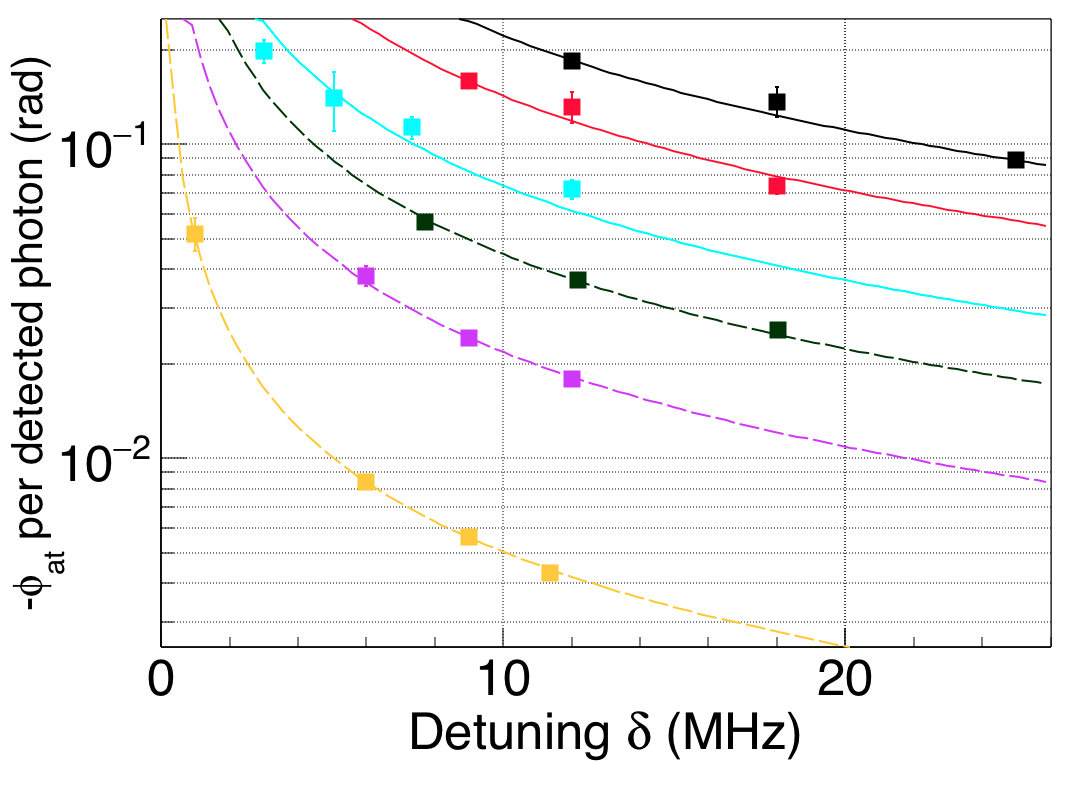
per detected photon. The system quantum efficiency is defined as , where and are the transmission of the input- and output-side mirrors, and are the loss at the input- and output-side mirrors, and is the loss between the output-side mirror and the photodetector including the detector’s quantum efficiency. Braverman (2018); Tanji-Suzuki et al. (2011b). The phase is measured as a population difference between the states after another pulse. Figure 4 shows the result of the phase measurements, including the small additional phase shift from the transition. The measurements at different detunings are fitted reasonably well by Eq. (3) with as the only fitting parameter. From these fits, the cooperativity at different atom positions is calculated, assuming the overall detection efficiency of an intracavity photon is 0.175(30), obtained from independent measurements of the cavity and photodetector properties. Note that the uncertainty of propagates into the estimate of as a systematic error.
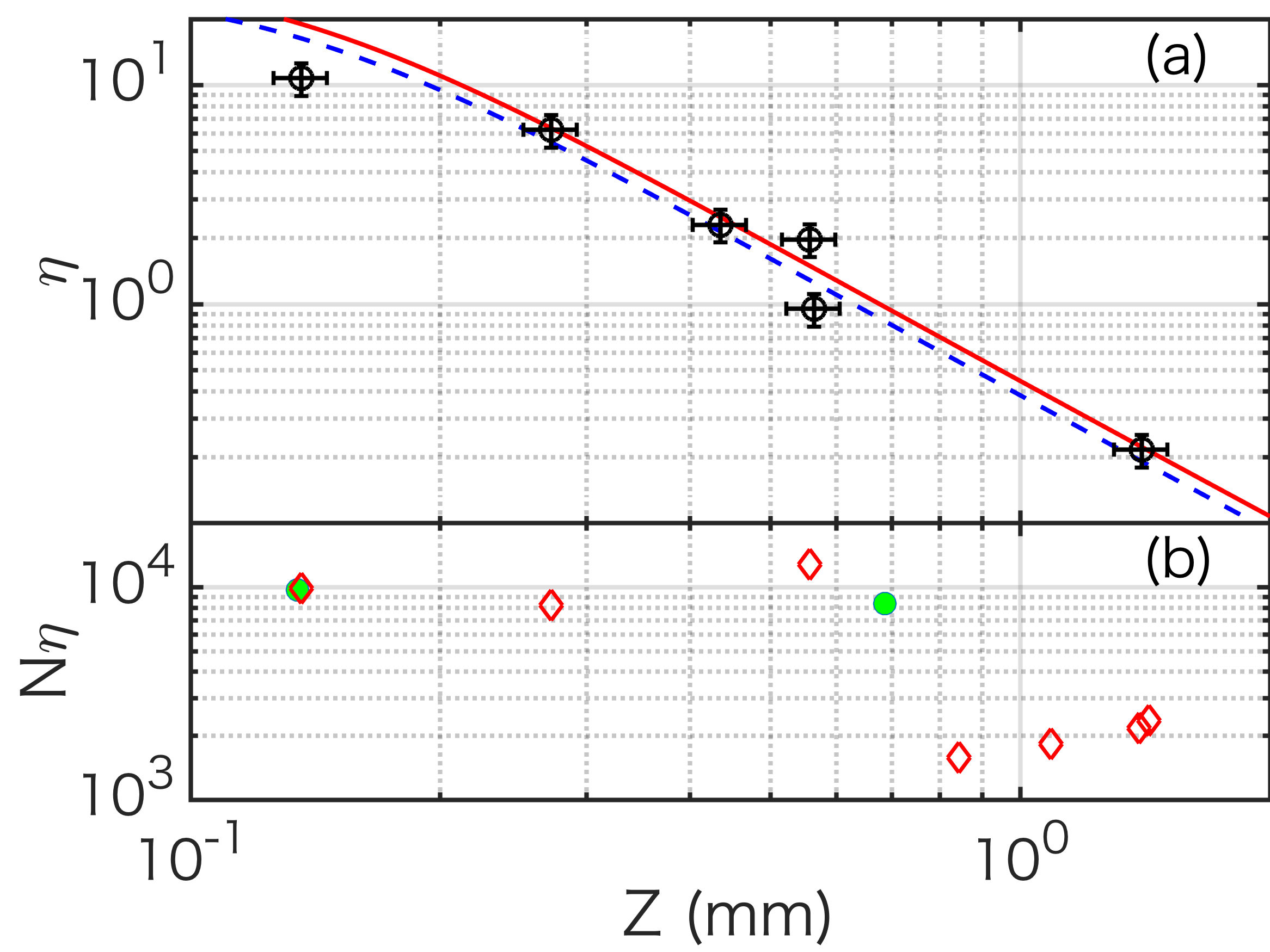
The measured effective single-atom cooperativity in this system ranges from to for atom-micromirror distances between mm and mm as shown in Fig. 5. The value of has systematic uncertainty of 7% due to uncertainty in the magnification of the imaging system. The measured effective cooperativity matches well with the calculated value, as shown in Fig. 5.
V.2 Collective cooperativity
To measure the collective cooperativity after trapping the atoms inside the cavity, we measure the vacuum Rabi splitting of the cavity resonance . is given by Tanji-Suzuki et al. (2011b)
| (4) |
For the measurement of , the atomic and cavity resonances are set to the same frequency , and a probing laser at 556 nm is sent into the system. The vacuum Rabi splitting is obtained by the phase and the power measurement of the transmitted probing laser whose frequency is scanned over the resonance peak. The scanning is performed by two sidebands to cancel the effect of the fluctuation of the cavity resonance frequency under the condition of , where the chirping frequency increases linearly in time.
Alternatively, one can also measure by measuring the dispersive shift of cavity resonance frequency , according to the following equation:
| (5) |
To perform this frequency shift measurement, is fixed as and the relative transmission through the cavity is measured. The values of derived from both methods agree with each other. Fig. 5(b) shows that collective cooperativities up to are observed for a wide range of atom positions . The observed values of are sufficiently large to permit significant cavity-feedback or measurement-based spin squeezing Schleier-Smith et al. (2010); Kawasaki (2017); Braverman (2018) in future experiments. The details of atom trapping to a small optical lattice are discussed elsewhere Braverman et al. .
VI Summary
We have constructed an asymmetric cavity reaching the single-atom strong-coupling regime, and have measured a cooperativity up to for 171Yb atoms on the transition. The asymmetric structure with a standard mirror and a micromirror ensures both large single-atom cooperativity and mechanical stability, as well as easy tuning of cooperativity by changing the atom position. Atom trapping is performed by a mirror MOT, and collective cooperativities in excess of are reached at atom-micromirror distances mm in a one-dimensional optical lattice with a lifetime exceeding 1 s. The measured single-atom cooperativity ranges from to , in agreement with the value expected from the cavity geometry and finesse. The large collective cooperativity we observe will enable spin squeezing in the ground-state manifold, which can then be mapped onto the atomic clock transition, as well as preparation of non-classical collective states Pezzè et al. (2018).
Acknowledgements.
This work is supported by DARPA Grant No. W911NF-11-1-0202, NSF Grants No. PHY-1505862 and No. PHY-1806765, NSF CUA Grant No. PHY-1734011, ONR Grant No. N00014-17-1-2254, and AFOSR MURI Grant No. FA9550-16-1-0323. B.B. acknowledges support from the National Science and Engineering Research Council of Canada. A.K. and B.B. contributed equally to this work.Appendix A How to assemble the asymmetric cavity with micromirror
The construction of the asymmetric cavity with a micromirror has to follow a specific procedure Braverman (2018), since the center of the large-ROC mirror has to be precisely aligned into a cone of 100 m diameter and 300 m height consisting of the micromirror and its center of curvature.
First, without the micromirror, the large-ROC mirror is aligned to the light that is sent from the micromirror side. The alignment is performed by matching the retroreflected light to the path of the incident laser beam. This aligns the large-ROC mirror to the optical axis of the cavity set by the input beam. Next, the micromirror is inserted. To do this, the flat part of the micromirror substrate is first used to make a cavity with the large-ROC mirror (flat-large ROC cavity), with transmission monitored by a CCD camera. If a cavity is formed, discrete transmission peaks corresponding to different transverse Hermite-Gaussian modes are observed. After the input light is aligned to couple mainly to the fundamental mode, the micromirror substrate is moved farther and farther from the large ROC mirror, until the cavity mode disappears. This ensures that the distance between the two mirrors is exactly the same as the ROC of the large-ROC mirror.
The third step is to align the transverse position of the micromirror substrate. This is performed simply by translating the substrate until strong scattered light from the micromirror is observed. At this point, the transmission often has two spots, corresponding to the cavity mode in a V-shaped configuration, with two points of reflection on the micromirror substrate. The goal is to merge these two spots into one, and this is the situation where a good cavity mode is formed for the asymmetric cavity.
Appendix B Details of the mechanical structure of the asymmetric cavity
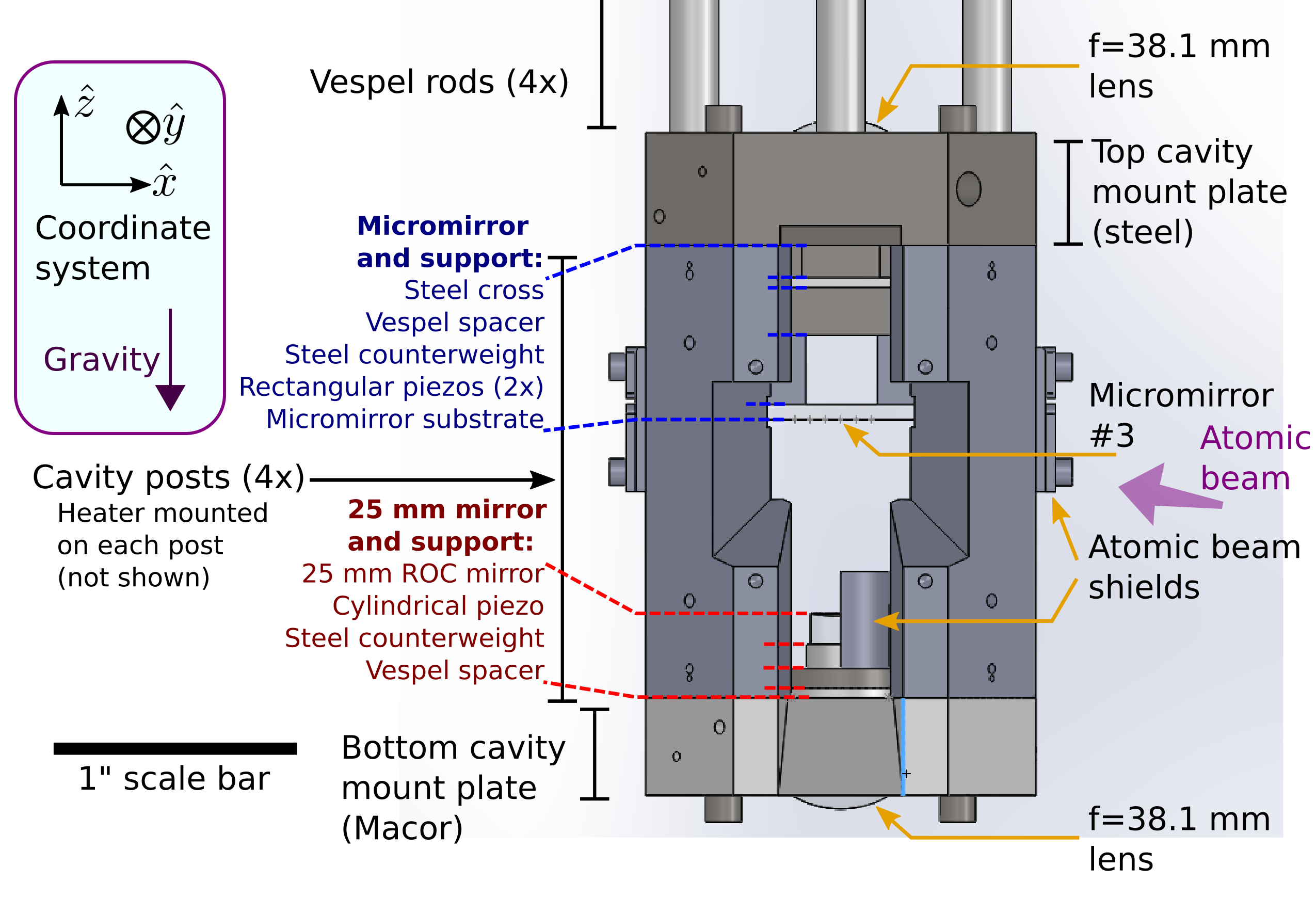
The mechanical structure supporting the cavity is shown in Fig. 6. Its main part consists of mounting plates for the micromirror (top) and the 25-mm-ROC mirror (bottom), connected by four posts. The structure is made of type 316 stainless steel for mechanical strength and small magnetization, except for the bottom mount plate made of macor glass-ceramic to prevent eddy currents over the whole structure when the magnetic field is switched. The posts are designed to be as thick as possible to have stiff connections between top and bottom mount plates, with openings to ensure a large enough optical access to the atoms. The cavity mirrors are mounted on piezoelectric actuators (PZTs). The 25 mm ROC mirror has a 0.125 in. long single-layer PZT (Channel Industries material C5700) for fast tuning, and the micromirror substrate is attached to two 6.5 m travel range, 9 mm long multistack PZTs (PI P-885.11) for slow but long-range tuning. Between each PZT and its mounting plate, a counterweight made of stainless steel and a damping layer made of polyimide-based plastic (VESPEL) is located to fully utilize the tuning of PZT for moving mirrors, without transmitting vibrations to the mounting structure. The top mount plate is suspended by thin VESPEL rods, in the middle of which stainless steel 4-40 screws tighten the cavity structure onto an adapter to a reducing flange, to dampen the vibrations from the environment through the adapter.
The 556 and 759 nm light is sent to the cavity from the bottom side, after proper mode shaping. The cavity length is tuned over short distances by the PZTs, and over long distances by adjusting the temperature of the whole cavity mount, which is stabilized by a servo circuit. Each pillar has its own heater, and heaters can be controlled independently. This large tuning is important to have the cavity simultaneously resonant for 556 nm light on the transition and 759 nm light close to the magic wavelength for the 578 nm clock transition. In addition, the independent control of the four heaters enables the fine tuning of the tilt between two mirrors, which plays an essential role in maximizing the finesse of the cavity at a given .
The cavity is locked to the 759 nm laser by Pound-Drever-Hall (PDH) locking Drever et al. (1983). To perform the frequency stabilization of the cavity, feedback is applied to the short PZT, which has a bandwidth of 6 kHz, limited by a mechanical resonance of the cavity holding structure. To complement the small tuning range of the short PZT, the long PZT is tuned by another servo circuit with a Hz bandwidth to compensate for the long term cavity length drift, in excess of the length tuning possible by the short PZT. The cavity resonance frequency near 556 nm is tuned into resonance with the atomic transition by adjusting the 759 nm light frequency. To trap atoms for a long time Savard et al. (1997), the intra cavity 759 nm light is intensity stabilized with a bandwidth of MHz. This provides dB suppression of the intensity noise of the intra-cavity light at kHz.
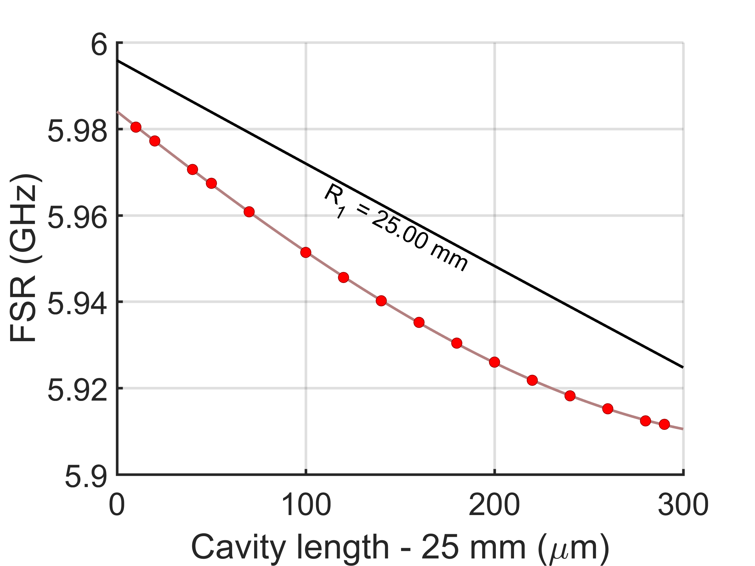
As mentioned in Section III, different measurement methods yield different distances between two mirrors of the asymmetric cavity. When the mirror distance of 25 mm (equal to , independently measured to equal mm) is calibrated by the disappearance of the stable cavity mode of the flat-large ROC cavity described in Appendix A, and then the micromirror is moved by a specific amount by a translational stage with a precision of 1 m (Thorlabs MBT616D), the mirror distance is recorded as mm. On the other hand, the measurement of FSR of 5970.04(4) MHz suggests mm. Figure 7 shows this discrepancy in terms of the measured FSR as a function of the distance between the two mirrors. The graph shows nonlinearity in the relation between the FSR and the cavity length, which clearly shows the deviation from the standard formula of . The tight waist exhibited by the asymmetric cavity leads to deviations from the paraxial approximation, which could cause corrections to the relationship between the cavity length and the FSR. However, we expect these corrections to be largest when the waist is small, i.e. and mm. The measurements (Fig. 7) produce the opposite behavior, leaving this phenomenon currently unexplained.
References
- Thompson et al. (1992) R. J. Thompson, G. Rempe, and H. J. Kimble, Phys. Rev. Lett. 68, 1132 (1992).
- Münstermann et al. (1999) P. Münstermann, T. Fischer, P. Maunz, P. W. H. Pinkse, and G. Rempe, Phys. Rev. Lett. 82, 3791 (1999).
- Nguyen et al. (2017) C. H. Nguyen, A. N. Utama, N. Lewty, K. Durak, G. Maslennikov, S. Straupe, M. Steiner, and C. Kurtsiefer, Phys. Rev. A 96, 031802 (2017).
- Reiserer and Rempe (2015) A. Reiserer and G. Rempe, Rev. Mod. Phys. 87, 1379 (2015).
- Miller et al. (2005) R. Miller, T. E. Northup, K. M. Birnbaum, A. Boca, A. D. Boozer, and H. J. Kimble, Journal of Physics B: Atomic, Molecular and Optical Physics 38, S551 (2005).
- Tanji-Suzuki et al. (2011a) H. Tanji-Suzuki, W. Chen, R. Landig, J. Simon, and V. Vuletić, Science 333, 1266 (2011a).
- Chen et al. (2011) Z. Chen, J. G. Bohnet, S. R. Sankar, J. Dai, and J. K. Thompson, Phys. Rev. Lett. 106, 133601 (2011).
- Haas et al. (2014) F. Haas, J. Volz, R. Gehr, J. Reichel, and J. Estève, Science 344, 180 (2014).
- Gupta et al. (2007) S. Gupta, K. L. Moore, K. W. Murch, and D. M. Stamper-Kurn, Phys. Rev. Lett. 99, 213601 (2007).
- Casabone et al. (2013) B. Casabone, A. Stute, K. Friebe, B. Brandstätter, K. Schüppert, R. Blatt, and T. E. Northup, Phys. Rev. Lett. 111, 100505 (2013).
- Birnbaum et al. (2005) K. M. Birnbaum, A. Boca, R. Miller, A. D. Boozer, T. E. Northup, and H. J. Kimble, Nature 436, 87 (2005).
- Chen et al. (2013) W. Chen, K. M. Beck, R. Bücker, M. Gullans, M. D. Lukin, H. Tanji-Suzuki, and V. Vuletić, Science 341, 768 (2013).
- Hacker et al. (2016) B. Hacker, S. Welte, G. Rempe, and S. Ritter, Nature 536, 193 (2016).
- Sun et al. (2018) S. Sun, H. Kim, Z. Luo, G. S. Solomon, and E. Waks, Science 361, 57 (2018).
- Reiserer et al. (2014) A. Reiserer, N. Kalb, G. Rempe, and S. Ritter, Nature 508, 237 (2014).
- Mitsch et al. (2014) R. Mitsch, C. Sayrin, B. Albrecht, P. Schneeweiss, and A. Rauschenbeutel, Nature Communications 5, 5713 (2014).
- Hosten et al. (2016) O. Hosten, N. J. Engelsen, R. Krishnakumar, and M. A. Kasevich, Nature 529, 505 (2016).
- Cox et al. (2016) K. C. Cox, G. P. Greve, J. M. Weiner, and J. K. Thompson, Phys. Rev. Lett. 116, 093602 (2016).
- Leroux et al. (2010) I. D. Leroux, M. H. Schleier-Smith, and V. Vuletić, Phys. Rev. Lett. 104, 073602 (2010).
- Béguin et al. (2014) J.-B. Béguin, E. M. Bookjans, S. L. Christensen, H. L. Sørensen, J. H. Müller, E. S. Polzik, and J. Appel, Phys. Rev. Lett. 113, 263603 (2014).
- McConnell et al. (2015) R. McConnell, H. Zhang, J. Hu, S. Ćuk, and V. Vuletić, Nature 519, 439 (2015).
- Northup and Blatt (2014) T. E. Northup and R. Blatt, Nature Photonics 8, 356 (2014).
- Stute et al. (2012) A. Stute, B. Casabone, B. Brandstätter, D. Habicher, H. G. Barros, P. O. Schmidt, T. E. Northup, and R. Blatt, Applied Physics B 107, 1145 (2012).
- Kimble (1998) H. J. Kimble, Physica Scripta 1998, 127 (1998).
- Tanji-Suzuki et al. (2011b) H. Tanji-Suzuki, I. D. Leroux, M. H. Schleier-Smith, M. Cetina, A. T. Grier, J. Simon, and V. Vuletić, in Advances in Atomic, Molecular, and Optical Physics, Advances In Atomic, Molecular, and Optical Physics, Vol. 60, edited by E. Arimondo, P. Berman, and C. Lin (Academic Press, 2011) pp. 201 – 237.
- Chen et al. (2015) W. Chen, J. Hu, Y. Duan, B. Braverman, H. Zhang, and V. Vuletić, Phys. Rev. Lett. 115, 250502 (2015).
- Siegman (1986) E. A. Siegman, Lasers (University Science Book, 1986).
- Cox et al. (2018) K. C. Cox, D. H. Meyer, N. A. Schine, F. K. Fatemi, and P. D. Kunz, Journal of Physics B: Atomic, Molecular and Optical Physics 51, 195002 (2018).
- Colombe et al. (2007) Y. Colombe, T. Steinmetz, G. Dubois, F. Linke, D. Hunger, and J. Reichel, Nature 450, 272 (2007).
- Fortier et al. (2007) K. M. Fortier, S. Y. Kim, M. J. Gibbons, P. Ahmadi, and M. S. Chapman, Phys. Rev. Lett. 98, 233601 (2007).
- Durak et al. (2014) K. Durak, C. H. Nguyen, V. Leong, S. Straupe, and C. Kurtsiefer, New Journal of Physics 16, 103002 (2014).
- Nguyen et al. (2018) C. Nguyen, A. N. Utama, N. Lewty, and C. Kurtsiefer, arXiv , 1806.03038 (2018).
- Hunger et al. (2010) D. Hunger, T. Steinmetz, Y. Colombe, C. Deutsch, T. W. Hänsch, and J. Reichel, New Journal of Physics 12, 065038 (2010).
- Braverman (2018) B. Braverman, Ph.D. Thesis in Physics, Massachusetts Institute of Technology (2018).
- Benedikter et al. (2015) J. Benedikter, T. Hümmer, M. Mader, B. Schlederer, J. Reichel, T. W. Hänsch, and D. Hunger, New Journal of Physics 17, 053051 (2015).
- Reichel et al. (1999) J. Reichel, W. Hänsel, and T. W. Hänsch, Phys. Rev. Lett. 83, 3398 (1999).
- Kawasaki et al. (2015) A. Kawasaki, B. Braverman, Q. Yu, and V. Vuletić, Journal of Physics B: Atomic, Molecular and Optical Physics 48, 155302 (2015).
- Schleier-Smith et al. (2010) M. H. Schleier-Smith, I. D. Leroux, and V. Vuletić, Phys. Rev. A 81, 021804 (2010).
- Chen et al. (2014) Z. Chen, J. G. Bohnet, J. M. Weiner, K. C. Cox, and J. K. Thompson, Phys. Rev. A 89, 043837 (2014).
- Hu et al. (2015) J. Hu, W. Chen, Z. Vendeiro, H. Zhang, and V. Vuletić, Phys. Rev. A 92, 063816 (2015).
- Kawasaki (2017) A. Kawasaki, Ph.D. Thesis in Physics, Massachusetts Institute of Technology (2017).
- (42) B. Braverman, A. Kawasaki, E. Pedrozo, C. Shu, S. Colombo, Z. Li, and V. Vuleti, Manuscript in preparation .
- Pezzè et al. (2018) L. Pezzè, A. Smerzi, M. K. Oberthaler, R. Schmied, and P. Treutlein, Rev. Mod. Phys. 90, 035005 (2018).
- Drever et al. (1983) R. W. P. Drever, J. L. Hall, F. V. Kowalski, J. Hough, G. M. Ford, A. J. Munley, and H. Ward, Applied Physics B 31, 97 (1983).
- Savard et al. (1997) T. A. Savard, K. M. O’Hara, and J. E. Thomas, Phys. Rev. A 56, R1095 (1997).