Experimental realization of a fast controlled-Z gate via a shortcut-to-adiabaticity
Abstract
For a frequency-tunable two-qubit system, a controlled-Z (CZ) gate can be realized by adiabatically driving the qubit system through an avoided level crossing between an auxiliary state and computational levels. Here, we theoretically propose a fast CZ gate using a shortcut-to-adiabaticity (STA). Experimentally, the STA CZ gate is implemented with a 52 ns control pulse for two coupled superconducting Xmon qubits. Measured fidelity of the STA CZ gate is higher than 96.0%, in both quantum process tomography and randomized benchmarking. The protocol allows a flexible design of the evolution time and control waveform. We suggest that this ‘fast adiabatic’ CZ gate can be directly applied to other multi-qubit quantum systems.
I I. Introduction
Quantum logic gates are the building blocks of quantum circuits in quantum computation ChuangBook ; LaddNat10 . The gate-based quantum computation requires a combination of single-qubit gates and a two-qubit entangling gate. Especially, the two-qubit gate is the foremost element in complex quantum algorithms. A controlled-Z (CZ) gate is a relatively common two qubit entangling gates, from which a controlled-NOT gate can also be generated WendinRep17 . Among different physical quantum systems, Superconducting qubit system has been one of the most promising candidates for quantum computation LaddNat10 ; WendinRep17 . Due to the lack of a ‘ZZ’ coupling DiCarloNat09 ; GhoshPRA13 ; MartinisPRA14 ; BarendsNat14 in superconducting transmon or Xmon qubits, it is difficult to realize the CZ gate directly in computational levels of each qubit (the ground and excited states). Instead, a CZ gate has been proposed to use non-computational energy levels (the second excited state) StrauchPRL03 . Driven adiabatically near the avoided level crossing between the two-qubit state and , the state can acquire a state-dependent phase, with other computational states unchanged. If the phase is designed as , a controlled -phase gate or the CZ gate can be realized.
However, a long time is required in the adiabatic evolution. Inevitable errors are introduced within the long procedure, due to the qubit decoherence and non-adiabatic leakage. In order to suppress such errors, Martinis et al. propose and realize a ‘fast adiabatic’ protocol of CZ gate, where a fast and specially designed drive reduces non-adiabatic errors as much as possible MartinisPRA14 ; BarendsNat14 . Another ‘fast adiabatic’ method is to use a shortcut-to-adiabaticity (STA) to completely eliminate non-adiabatic transitions DemirplakJPCA03 ; BerryJPhysA09 ; XChenPRL2010 ; MasudaPRS10 ; Torrontegui13AAMOPhy ; CampoPRL12 ; CampoPRL13 ; TongSR15 ; SantosSR15 . By introducing a counter-dibatic (CD) field, the STA protocol can force the quantum state to remain in the instantaneous eigenstate of the reference Hamiltonian. The STA protocol has been extensively applied to control the state evolution of a single qubit, in cold atoms BasonNatPhy11 ; DuYXNatCommu16 , NV centers JFZhangPRL13 ; ZhouNatPhys16 , trapped-ion AnNatCommu16 and superconducting qubits ZZXPRA17 ; SCPMA2018 ; WangNJP2018 ; ZZXNJP2018 . Applying the STA protocol in a multi-qubit system is yet a nontrivial task.
In this paper, we propose and implement a CZ gate for two coupled superconducting Xmon qubits, using a STA protocol. In the subspace of and states, the STA protocol is directly applied to derive a ‘fast adiabatic’ waveform. A practical problem is that this drive requires a variable complex coupling between qubits, instead of a fixed coupling in the real system. The problem is resolved by introducing a representation transformation and a rescaling method. Following the theoretical model, the protocol is experimentally realized in our Xmon qubit system. The measurement fidelity are over 96% for both the quantum process tomography (QPT) and the randomized benchmark (RB). An interleaved RB is also implemented with a fidelity about 94%. The fidelity can be further improved, with a better multi-qubit system in the future.
II II. Theoretical Protocol
For two coupled Xmon qubits, the system Hamiltonian is
| (1) |
where is the single qubit Hamiltonian, and is the coupling term. With lowest three levels of a Xmon considered, the single qubit Hamiltonian can be expressed as
| (2) |
where is the reduced Planck constant, is the energy difference between the ground and excited states of the qubit QA(B), and is the anharmonicity for both Xmons. The coupling term is expressed as
| (3) |
where is the coupling strength, is the lowering operator for a three level system, and H.c. stands for the Hermitian conjugate.
II.1 A. Adiabatic evolution in subspace
We consider a subspace including two-qubit states and . In both states, the 1st and 2nd numbers represent the qubit state of QA and QB, respectively. The energy of is , while the energy of is . In our system, the difference between two qubit frequencies is initially set at MHz. With the anharmonicity MHz, the energy of is initially much larger than that of .
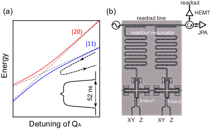
If we fix and slowly lower , the energy difference between and will decrease correspondingly. As shown in the energy level diagram (Fig. 1(a)), this detuning will gradually bring into an avoided level crossing with . Following a designed adiabatic trajectory (black dashed line in Fig. 1(a)), an initialized state will adiabatically evolve along the instantaneous eigenstate (solid blue line) and be brought back to the state. Without a non-adiabatic leakage, a dynamic phase is accumulated in the final state . The dynamic phase , including an extra phase in addition to the trivial dynamic phase of single Xmons. Because the subspace Hamiltonian can be written as
| (4) |
we obtain the extra phase , where is the polar angle with , and is the frequency difference between and .
For a state initialized at , , or , the same detuning procedure will not induce extra dynamic phase because these states are off-resonance with both avoided-level crossings. Then the total unitary operator for the computational level can be written as
| (5) |
Removing the trivial dynamic phase of single Xmons, the unitary operator reduces to
| (6) |
where is the control phase. By adjusting the evolution path of , we can implement an arbitrary two-qubit control phase gate.
II.2 B. STA protocol and rescaled Hamiltonian
In general, a time-dependent Hamiltonian can be expanded in its instantaneous eigen basis, i.e., , where is the -th eigenenergy and is the -th eigenstate. According to the STA protocol, a counter-diabatic Hamiltonian is formally written as BerryJPhysA09
| (7) |
When the system is driven with a total Hamiltonian of , the non-adiabatic transition can be suppressed within a short operation time. In the subspace of and , we apply the STA protocol to the previous adiabatic trajectory. The counter-diabatic Hamiltonian is calculated as }. Practically, we can not physically generate an imaginary coupling term in the subspace. To remove the imaginary coupling, we introduce an unitary transformation . After shifting the diagonal energy, the subspace Hamiltonian is rewritten as IbanezPRL12
| (8) |
where , and is the azimuth angle in the Hamiltonian of with . In , the off-diagnoal term is time-dependent, which can be realized if is a tunable coupling between two qubits ChenPRl14 ; RoushanNatPhys17 ; RoushanSci17 . In our Xmon sample, the capacitive coupling is fixed between neighboring qubits, resulting in a fixed off-diagonal term of in the subspace Hamiltonian. Then we need to find a new rescaled Hamiltonian to realize the same function as with .
We divide the original to segments, each of duration . With a sufficiently large , the unitary operator for the -th duration is
| (9) |
To acquire a constant off-diagonal term, the new rescaled Hamiltonian of the -th segment can be defined as
| (10) |
and the duration time for the -th segment is rescaled as
| (11) |
The unitary operator is kept the same as before for each segment, although the time is rescaled to fix the off-diagonal term of the subspace Hamiltonian. Correspondingly, the time-dependent form of is rewritten as . Combining the unitary transformation IbanezPRL12 and the rescaling approach JFZhangPRL13 , we apply the STA protocol in the coupled Xmon qubit system to implement a fast control phase gate.
III III. Experimental Setup
Figure 1(b) displays an optical micrograph of two coupled Xmon qubits on a chip sample. The fabrication of the chip is the same as described before WangNJP2018 . The qubit chip is mounted in an aluminum sample box and cooled in a dilution refrigerator whose base temperature is about 10 mK. For each Xmon, four arms of the cross are connected to a readout resonator (top), control lines (bottom) and neighboring Xmons. Through the control line, a flux current is supplied to bias the Xmon qubit at an operation frequency. In our experiment, two Xmon qubits are initially biased at GHz and GHz, respectively. The qubit anharmonicity is MHz for both Xmons. At these operation points, the energy relaxation time are 14.4 s and 12.9 s, and the pure decoherence time are 12.3 s and 3.5 s for QA and QB respectively. The second qubit is biased far away from the sweet point, resulting in a relative shorter decoherence time. The control line provides a microwave drive signal to the qubit to manipulate the qubit state.
At the end of any qubit manipulation, the qubit state is encoded in a coupled readout resonator, and can be detected by a dispersive readout. The bare frequency of readout resonators are GHz and GHz for QA and QB, respectively. In the dispersive readout, a microwave measurement signal is sent through the readout line, interacting with the readout resonator. After amplified by a Josephson parametric amplifier (JPA) RoyAPL15 and a high electron mobility transistor (HEMT), the readout signal is finally collected. The readout fidelity of the ground state and excited state are , and , for QA and QB respectively. In addition, the on chip wire-bonding is applied across the control line to reduce the crosstalk. The measured crosstalk coefficients are -6%(QQA) and 4%(QQB) BarendsNat14 .
IV IV. Results
To obtain accurate parameters of the coupled two qubits, we measure a swap spectroscopy between and states. In Fig. 2(a), we show a schematic pulse sequence of the swap spectroscopy. By applying a -pulse to each qubit, two qubits are initially prepared in the state. Then a rectangle detuning pulse is applied to QA to lower its frequency . When equals , the state will resonate with . The states of two qubits are finally measured simultaneously, with a dispersive readout. In Fig. 2(b), we plot the measured probability versus the detuning time and the detuned . A typical chevron pattern can be observed, which reveals a quantum state oscillates between and . Theoretically, the probability oscillates with a swap frequency . For a specific , we take the fourier transform of the oscillation, from which is extracted. In Fig. 2(c), we plot the extracted oscillation frequency as a function of , and make a curve fitting with the theoretical formula of . The fitting result leads to an accurate estimation of the coupling strength MHz and the resonant frequency GHz. These two parameters facilitate the following design of a STA waveform for the CZ gate.
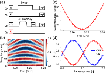
In principle, the control pulse can be designed with different functions, whenever they are compatible with the theoretical protocol. In this work, we select a Hanning-Window function for , i.e., , with for the first half of the trajectory. The polar angle is the initial polar angle in our system, and is the maximum polar angle in the trajectory. For the CZ gate, the control phase is , leading to a maximum polar angle . After reaches the maximum angle , the 2nd half of the trajectory is applied immediately, as (). The total time is chosen to be 40 ns in our design. For the whole trajectory, the function of is given by . This control function gives , which allows a smooth change of at the start and end of the sequence. Finally, the rescaled can be obtained with Eq. 10 and Eq. 11. The total evolution time is about 52 ns after rescaling. The rescaled pulse for the CZ gate is shown in the inset of Fig. 1(a), where an obvious protuberance can be observed in the middle.
Before applying the designed pulse to implement a CZ gate, we need to determine the additional dynamic phase accumulated in a single qubit, which is measured in the following Ramsey fringe experiment YamamotoPRB10 . A -pulse is initially applied to QA to create a superposition state of . A CZ pulse is then applied. The detuning of induces an extra dynamic phase for QA. A second -pulse is finally applied to complete the Ramsey fringe process. If there is no CZ pulse in the middle between two pulses, QA will be brought to the first excited state . If the second -pulse is applied with a variable phase (Ramsey phase), QA state will project to with a cosinusoid probability. The additional dynamic phase will, however, shift the phase of the cosinusoid function. Figure 2(d) presents the final probability of versus the Ramsey phase. We could observe that the maximum appears at a finite phase, instead of the zero phase. This shifted phase equals the accumulated dynamic phase we need. A cosinusoid fitting gives us an accurate phase value to compensate the additional dynamical phase during CZ gate. Furthermore, to confirm the operation of CZ gate, we compare the Ramsey fringe experiment with QB initialized in or . If QB is initially excited to , QA will acquire an extra controlled phase, compared to the previous Ramsey fringe experiment. In Fig. 2(d), we plot the results of two Ramsey fringe experiments, with QB initialized in or . A phase difference can be clearly observed, which verifies the operation of our CZ gate.
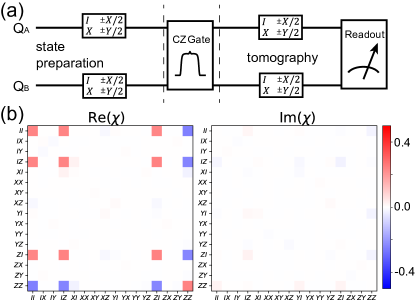
To quantify the CZ gate fidelity, we perform a quantum process tomography (QPT) of the CZ gate. In the QPT procedure, the output state is obtained through a map of the input state ChuangBook , i.e.,
| (12) |
where the initial density matrix of the two-qubit system. Each linear operators can be expanded by a fixed set of operators , giving . The operator basis can be acquired from the Kronecker product of pauli operators of each qubit. The output density matrix can then be rewritten as
| (13) |
with . The matrix thus completely characterizes the behavior of a specific gate, although including errors in the state preparation and measurement.
Figure 3(a) shows the pulse sequence for the QPT. Different input states are initially prepared, from the set for each qubit BialczakNatPhys10 ; YamamotoPRB10 ; ChuangBook . A CZ pulse is then applied. Afterwards, the output state is measured by the quantum state tomography (QST). The matrix is numerically calculated by solving Eq. (13). The experimental result of the matrix is plotted in Figs. 3(b). Consistent with the theoretical prediction of a matrix for an ideal CZ gate, the dominant elements are the operator of and . To quantify the fidelity of the whole quantum process, we calculate the process fidelity using ChuangBook , with a result of . To figure out the error source, we compare our result with a numerical calculation. Without decoherence, the calculated process fidelity is 99.94%, which means that our STA protocol can realize a CZ gate with very high fidelity in the ideal situation. With decoherence parameters considered, the numerical simulation gives a process fidelity of 98.43%. Compared with our experimental result, we could presume that the qubit decoherence is one of the main loss sources of the process fidelity, together with some other residual control errors.
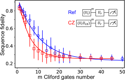
In the above QPT measurement, the errors of state preparation and readout are mixed with the error of a quantum gate operation. To separately extract the gate fidelity, we perform a Clifford-based RB measurement KnillPRA08 ; MagesanPRL12_RB ; ChowPRL09 ; BarendsNat14 ; SheldonPRA16 . For a two-qubit system, the Clifford group consists of 11520 gate operations. In principle, each Clifford gate can be realized by a combination from the set of single qubit gates and CZ gate. As shown in the pulse sequence in the inset of Fig. 4, two qubits are initially prepared at the state, and then driven by a sequence of randomly selected Clifford gates. A unitary matrix, , describes the combined operation. still belongs to the closed set of Clifford group. The -th step reverses the previous combined operations, and the total quantum operation can be expressed as . At the end we measure the remaining population of the initial state. This whole process has been repeated for (= 40 in our experiment) times, and we calculate the average result of as a function of the Clifford gate numbers . In Fig. 4, this sequence fidelity has been fitted by a power-law decaying function MagesanPRL12_RB , , in which is a reference depolarizing parameter, and and include errors in state preparation and readout. With the depolarizing parameter, the average error over randomized Clifford gates is calculated as , where is the Hilbert space dimension for the two-qubit system. The average error consists of single gates error and CZ gate error, . In our experiment, the average error and single qubit error are and , respectively. The average CZ gate fidelity is calculated to be .
We also make an interleaved operation MagesanPRL12_RB to extract the CZ gate fidelity. The pulse sequence is also shown in the inset of Fig. 4, in which the CZ gate is interleaved in the randomly select Clifford operator. With the product operator for each step, , and the -th operator of , we describe the total operation as BarendsNat14 ; MagesanPRL12_RB . The sequence fidelity is similarly measured. As shown by the red circle in Fig. 4, can also be fitted by a power-law decaying function, giving a new depolarizing parameter . Then we calculate the CZ gate fidelity by
| (14) |
In this interleaving RB measurement, the CZ gate fidelity is , which is smaller than the above average fidelity. This difference may be from the imperfect Z control.
V V. Summary
We propose a method to realize a fast CZ gate using the STA protocol. Through a representation transformation and a rescaled Hamiltonian, we achieve a ‘fast adiabatic’ evolution with only qubit frequency control. In the absence of the qubit decoherence, the QPT fidelity of numerical calculation is over 99.9%, proven to be a high fidelity CZ gate in the ideal situation. As an example, we experimentally implement this CZ gate in two coupled superconducting Xmon qubits. Experimental parameters are acquired from the swap spectroscopy and Ramsey fringe experiment. From the QPT and RB measurement, the CZ gate fidelities are confirmed to be above 96%. An interleaved RB experiment is also performed to give a fidelity of about 94%, suggesting a control error from the residue settling in Z pulse. Our protocol provides a feasible ‘fast adiabatic’ method of CZ gate. In principle, the protocol allows a large flexibility in the evolution time and control waveform, and can be directly applied in other quantum systems. The fidelity can be further increased, with the sample quality and control accuracy improved in the future.
VI acknowledgements
Acknowledgements.
The work reported here is supported by the National Basic Research Program of China (2014CB921203, 2015CB921004), the National Key Research and Development Program of China (2016YFA0301700), the National Natural Science Foundation of China (NSFC-21573195, 11625419), the Fundamental Research Funds for the Central Universities in China, and the Anhui Initiative in Quantum Information Technologies (AHY080000). This work was partially carried out at the University of Science and Technology of China Center for Micro and Nanoscale Research and Fabrication.References
- (1) M. A. Nielsen and I. Chuang, Quantum computation and quantum information, (2002).
- (2) T. D. Ladd, F. Jelezko, R. Laflamme, Y. Nakamura, C. Monroe, and J. L. OBrien,Quantum computers, Nature 464, 45 (2010).
- (3) G. Wendin, Quantum information processing with superconducting circuits: a review, Reports on Progress in Physics 80, 106001 (2017).
- (4) L. DiCarlo, J. Chow, J. Gambetta, L. S. Bishop, B. Johnson, D. Schuster, J. Majer, A. Blais, L. Frunzio, S. Girvin, et al., Demonstration of two-qubit algorithms with a superconducting quantum processor, Nature 460, 240 (2009).
- (5) J. Ghosh, A. Galiautdinov, Z. Zhou, A. N. Korotkov, J. M. Martinis, and M. R. Geller, High-fidelity controlled- gate for resonator-based superconducting quantum computers, Phys. Rev. A 87, 022309 (2013).
- (6) J. M. Martinis and M. R. Geller, Fast adiabatic qubit gates using only control, Phys. Rev. A 90, 022307 (2014).
- (7) R. Barends, J. Kelly, A. Megrant, A. Veitia, D. Sank, E. Jeffrey, T. C. White, J. Mutus, A. G. Fowler, B. Campbell, et al., Superconducting quantum circuits at the surface code threshold for fault tolerance, Nature 508, 500 (2014).
- (8) F. W. Strauch, P. R. Johnson, A. J. Dragt, C. J. Lobb, J. R. Anderson and F. C. Wellstood, Quantum Logic Gates for Coupled Superconducting Phase Qubits, Phys. Rev. Lett. 91, 167005 (2003).
- (9) M. Demirplak and S. A. Rice, Adiabatic population transfer with control fields, The Journal of Physical Chemistry A 107, 9937 (2003).
- (10) M. Berry, Transitionless quantum driving, Journal of Physics A: Mathematical and Theoretical 42, 365303 (2009).
- (11) X. Chen, I. Lizuain, A. Ruschhaupt, D. Guéry-Odelin and J. Muga, Shortcut to adiabatic passage in two-and three-level atoms, Phys. Rev. Lett. 105, 123003 (2010).
- (12) S. Masuda and K. Nakamura, Fast-forward of adiabatic dynamics in quantum mechanics, in Proceedings of the Royal Society of London A: Mathematical, Physical and Engineering Sciences, Vol. 466 (The Royal Society, 2010) pp.1135 C1154.
- (13) E. Torrontegui, S. Ibáñez, S. Martínez-Garaot, M. Modugno, del Campo A, D. Guéry-Odelin , A. Ruschhaupt, X. Chen and J. Muga, Shortcuts to adiabaticity, in Advances in atomic, molecular, and optical physics, Vol. 62 (Elsevier, 2013) pp. 117 C169.
- (14) del Campo A, M. M. Rams and W. H. Zurek, Assisted finite-rate adiabatic passage across a quantum critical point: exact solution for the quantum Ising model, Phys. Rev. Lett. 109, 115703 (2012).
- (15) del Campo A, Shortcuts to adiabaticity by counterdiabatic driving, Phys. Rev. Lett. 111, 100502 (2013).
- (16) J. Zhang, T. H. Kyaw, D. M. Tong, E. Sjöqvist and L. C. Kwek, Fast non-Abelian geometric gates via transitionless quantum driving, Sci. Rep. 5, 18414 (2015).
- (17) A. C. Santos and M. S. Sarandy, Superadiabatic Controlled Evolutions and Universal Quantum Computation, Sci. Rep. 5, 15775 (2015).
- (18) M. G. Bason, M. Viteau, N. Malossi, P. Huillery, E. Arimondo, D. Ciampini, R. Fazio, V. Giovannetti, R. Mannella and O. Morsch, High-fidelity quantum driving, Nat. Phys. 8, 147 (2012).
- (19) Y. X. Du, Z. T. Liang, Y. C. Li, X. X. Yue, Q. X. Lv, W. Huang, X. Chen, H. Yan and S. L. Zhu, Experimental realization of stimulated Raman shortcut-to-adiabatic passage with cold atoms, Nat. Commun. 7, 12479 (2016).
- (20) J. Zhang, J. H. Shim, I. Niemeyer, T. Taniguchi, T. Teraji, H. Abe, S. Onoda, T. Yamamoto, T. Ohshima, J. Isoya, et al., Experimental implementation of assisted quantum adiabatic passage in a single spin, Phys. Rev. Lett. 110, 240501 (2013).
- (21) B. B. Zhou, A. Baksic, H. Ribeiro, C. G. Yale, F. J. Heremans, P. C. Jerger, A. Auer, G. Burkard, A. A. Clerk and D. D. Awschalom, Accelerated quantum control using superadiabatic dynamics in a solid-state lambda system, Nat. Phys. 13, 330 (2017).
- (22) S. M. An, D. S. Lv, del Campo A and K. Kim, Shortcuts to adiabaticity by counterdiabatic driving for trapped-ion displacement in phase space, Nat. Commun. 7, 12999 (2016).
- (23) Z. Zhang, T. Wang, L. Xiang, J. Yao, J. Wu and Y. Yin, Measuring the Berry phase in a superconducting phase qubit by a shortcut to adiabaticity, Phys. Rev. A 95, 042345 (2017).
- (24) T. Wang, Z. Zhang, L. Xiang, Z. Gong, J. Wu and Y. Yin, Simulating a topological transition in a superconducting phase qubit by fast adiabatic trajectories, Sci. China Phys. Mech. 61, 047411 (2018).
- (25) Z. Zhang, T. Wang, L. Xiang, Z. Jia, P. Duan, W. Cai, Z. Zhan, Z. Zong, J. Wu, L. Sun, Y. Yin and G. Guo, Experimental demonstration of work fluctuations along a shortcut to adiabaticity with a superconducting Xmon qubit, New J. Phys. 20, 085001 (2018).
- (26) T. Wang, Z. Zhang, L. Xiang, Z. Jia, P. Duan, W. Cai, Z. Gong, Z. Zong, M. Wu, J. Wu, et al., The experimental realization of high-fidelity shortcut-to-adiabaticity quantum gates in a superconducting Xmon qubit, New J. Phys. 20, 065003 (2018).
- (27) S. Ibáñez, X. Chen, E. Torrontegui, J. Muga and A. Ruschhaupt, Multiple Schrödinger pictures and dynamics in shortcuts to adiabaticity, Phys. Rev. Lett. 109, 100403 (2012).
- (28) Y. Chen, C. Neill, P. Roushan, N. Leung, M. Fang, R. Barends, J. Kelly, B. Campbell, Z. Chen, B. Chiaro, et al., Coherent Josephson qubit suitable for scalable quantum integrated circuits, Phys. Rev. Lett. 113, 220502 (2014).
- (29) P. Roushan, C. Neill, A. Megrant, Y. Chen, R. Babbush, R. Barends, B. Campbell, Z. Chen, B. Chiaro, A. Dunsworth, A. Fowler, et al., Chiral ground-state currents of interacting photons in a synthetic magnetic field, Nat. Phys. 13, 146 (2017).
- (30) P. Roushan, C. Neill, J. Tangpanitanon, V. M. Bastidas, A. Megrant, R. Barends, Y. Chen, Z. Chen, B. Chiaro, A. Dunsworth, et al., Spectroscopic signatures of localization with interacting photons in superconducting qubits, Science, 358 (6367), 1175-1179 (2017).
- (31) T. Roy, S. Kundu, M. Chand, A. Vadiraj, A. Ranadive, N. Nehra, M. P. Patankar, J. Aumentado, A. Clerk, and R. Vijay, Broadband parametric amplification with impedance engineering: Beyond the gain-bandwidth product, Appl. Phys. Lett. 107, 262601 (2015).
- (32) T. Yamamoto, M. Neeley, E. Lucero, R. Bialczak, J. Kelly, M. Lenander, M. Mariantoni, A. OConnell, D. Sank, H. Wang, et al., Quantum process tomography of two-qubit controlled-Z and controlled-NOT gates using superconducting phase qubits, Phys. Rev. B 82, 184515 (2010).
- (33) R. C. Bialczak, M. Ansmann, M. Hofheinz, E. Lucero, M. Neeley, A. OConnell, D. Sank, H. Wang, J. Wenner, M. Steffen, et al., Quantum process tomography of a universal entangling gate implemented with Josephson phase qubits, Nat. Phys. 6, 409 (2010).
- (34) E. Knill, D. Leibfried, R. Reichle, J.Britton, R. Blakestad, J. D. Jost, C. Langer, R. Ozeri, S. Seidelin, and D. J. Wineland, Randomized benchmarking of quantum gates, Phys. Rev. A 77, 012307 (2008).
- (35) E. Magesan, J. M. Gambetta, B. R. Johnson, C. A. Ryan, J. M. Chow, S. T. Merkel, M. P. Da Silva, G. A. Keefe, M. B. Rothwell, T. A. Ohki, et al., Efficient measurement of quantum gate error by interleaved randomized benchmarking, Phys. Rev. Lett. 109, 080505 (2012).
- (36) J. Chow, J. M. Gambetta, L. Tornberg, J. Koch, L. S. Bishop, A. A. Houck, B. Johnson, L. Frunzio, S. M. Girvin, and R. J. Schoelkopf, Randomized benchmarking and process tomography for gate errors in a solid-state qubit, Phys. Rev. Lett. 102, 090502 (2009).
- (37) S. Sheldon, L. S. Bishop, E. Magesan, S. Filipp, J. M. Chow, and J. M. Gambetta, Characterizing errors on qubit operations via iterative randomized benchmarking, Phys. Rev. A 93, 012301 (2016).