|
|
Microfluidic probing of the complex interfacial rheology of multilayer capsules. |
| Corentin Trégouëtab, Thomas Salez cd, Cécile Monteux bd and Mathilde Reyssat a | |
|
|
Encapsulation of chemicals using polymer membranes enables to control their transport and delivery for applications such as agrochemistry or detergency. To rationalize the design of polymer capsules, it is necessary to understand how the membranes’ mechanical properties control the transport and release of the cargo. In this article, we use microfluidics to produce model polymer capsules and study in situ their behavior in controlled elongational flows. Our model capsules are obtained by assembling polymer mono and hydrogen-bonded bilayers at the surface of an oil droplet in water. We also use microfluidics to probe in situ the mechanical properties of the membranes in a controlled elongational flow generated by introducing the capsules through a constriction and then in a larger chamber. The deformation and relaxation of the capsules depend on their composition and especially on the molecular interactions between the polymer chains that form the membranes and the anchoring energy of the first layer. We develop a model and perform numerical simulations to extract the main interfacial properties of the capsules from the measurement of their deformations in the microchannels. |
1 Introduction
Droplets with valuable content can be protected from their environment by a membrane, usually elastic, which turns them into capsules. Encapsulation of droplets allows a better control on the delivery of the droplet content. Capsules are used in a very broad range of applications such as food industry 1, drug delivery 2, 3, material science 4 or cosmetics 5. Various types of processes have been developed in the last decades to produce capsules, especially thanks to the development of microfluidic technics 6, 7, 8, 9, 10, 11, 12, 13.
To rationalize the formulation of capsules it is necessary to understand the link between the composition of the protecting membrane, its mechanical properties and the performances of the capsules, which requires model polymer membranes as well as experimental techniques to determine capsule mechanical properties. New experimental techniques have been developed to characterize elastic polymer membranes at liquid interfaces 14, 15, 16, 17, 18. The rheology of such membranes has been studied in model geometries 19, 20, 21, 22, 17, 23, 15 and also on real capsules in viscous flows to mimic real conditions of fabrication and use, through various experiments 24, 25, 26, 23, 16, theories 27, 28, 29 and simulations 30, 31, 32. From this perspective, microfluidics is an ideal tool which allows to integrate measurement units directly in situ in the devices and to perform automated measurements on a large number of capsules.
The use of extensional flows to measure the surface properties of droplets has been first developed by Taylor 33 with the so-called four-roller apparatus. Since then, this method has been adapted in microfluidics by imposing an extensional flow field to droplets at a transition between a narrow channel and a larger chamber, and has been firstly employed to measure interfacial tensions 34, 35. In our previous work 35, by simulating the flow field in the large chamber we were able to determine the shear forces applying on the capsules. Assuming a competition between the viscous forces deforming the capsules and the interfacial tension force restoring its shape, we were then able to predict the shape of the droplet as a function of its position in the channel for a given interfacial tension. Inversely, the fit of our experimental data with the model enabled to deduce the interfacial tension of the droplets.
Recently, similar design has been used to measure the elastic modulus of capsules 36, 37, 38. However, for intermediate situations where several interfacial components can interfere (for example in the case of visco-elastic capsules for which the interfacial tension force is not negligible), there is no model which can rationalize the evolution of the capsules deformation over time by accounting for the relative importances of membrane viscoelastic properties and interfacial tension.
In previous studies published in our group 5, 39, 40, we have designed model polymer membranes with controlled interfacial properties. These membranes are obtained by assembling polymer multilayers at oil water interfaces through hydrogen bonds. We have shown that the hydrophobicity of the polymers enables to control the interaction energy of the assembled layers by an interplay of hydrogen bonds and hydrophobic interactions, which tunes the shear moduli of the membrane. Moreover, controlling the anchoring energy of the chains by adding hydrophobic anchors on the chains enables to control the compression moduli of the adsorbed layers.
In the present article, our goal is to study the relation between the composition of the polymer membranes protecting the droplets and the deformation of capsules in a controlled flow field. We produce, using microfluidics, monodisperse populations of oil droplets covered by polymer multilayers of various compositions described above and we study their deformation in microfluidic extensional flows, obtained by the combination of a constriction followed by a larger chamber. We find that the dynamics of the capsules under this extensional flow strongly depends on the composition of the multilayers. We propose a coarse-grained model to extract the different characteristic properties of each polymer membrane, and evaluate the relative importances of the various factors ruling the capsule’s deformation.
2 Materials and methods
Oil droplets in aqueous solutions are covered with polymers in a microfluidic chip, and directed through an extensional flow to measure their deformation and relaxation.
2.1 Materials
2.1.1 Liquids and polymers
The droplets consist of mineral oil (Sigma Aldrich, Mineral Oil Rotational Viscosity Standard of viscosity at ) flowing in different polymer solutions, prepared at and adjusted at pH with molar solutions of HCl or NaOH.
In recent articles 5, 39 we have studied the interfacial rheological properties of polymer multi layers assembled at oil water interfaces by hydrogen bonds.
The polymers used to obtain the multilayers are:
-
•
poly(methacrylic acid), (PMAA) provided by Polysciences, ,
-
•
poly(vinyl pyrrolidone), (PVP) provided by Fluka, ,
-
•
covalently randomly hydrophobically modified poly(acrylic acid) PAA--C12 and PAA--C8: respectively and of the monomers are grafted to an alkyl chain of 12 and 8 carbons respectively, the backbone being provided by Polysciences Inc., . We prepared these polymers by following the protocol of Wang et al.41. The grafting density has been measured by proton NMR.
The droplets are characterized in the polymer solution leading to the last adsorbed layer.
2.1.2 Microfluidic chips
The droplets are produced by microfluidics using a standard flow-focusing device made of poly(dimethyl siloxane) (PDMS) in the production chip 35. Such a setup provides a very monodisperse collection of droplets, tunable from 50 to 70 in diameter depending on the experimental conditions. As described in the following, we design specific connections to add a second polymer layer. The production chip is further connected to a characterization chip realized with a photosensitive adhesive provided by Norland (NOA 81). This microfabrication technique is a way to build rigid channels confined between two glass surfaces, and able to sustain large flow rates without being deformed 42. The inlet of the chip is connected to the droplet-production chip by a silicon tubing (Tygon) of inner diameter , coated with a solution of Bovine Serum Albumine (BSA) (Sigma Aldrich) to prevent adhesion of the droplets inside the tubing (incubation at solution during at room temperature), whereas its outlet is connected to a Peek tubing of inner diameter .
2.2 Methods
2.2.1 Fabrication of multilayers
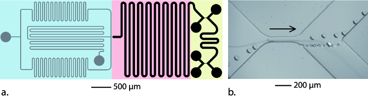
The set-up is sketched in Figure 1. Our first objective is to build capsules with a multilayer membrane. Once the droplets are produced 35, they are forced to circulate into a long serpentine to let the first polymer adsorb at their surfaces 8. The addition of a second polymer layer is done in two steps. First, the droplets are transferred to a solution of HCl (pH 3) through a pinched-flow fractionation as described by Yamada et al.43 and illustrated in Figure 1 b. Secondly, using the same method, the droplets are transferred from the HCl solution to a second polymer solution.
2.2.2 Capsule deformation
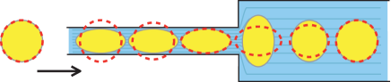
The principles of capsule deformation and observation were described previously 35. Briefly, the characterization chip (Figure 2) consists in a sharp transition between a narrow channel (of width ) and a wide chamber (of width ), similar to the chip used by Polenz et al. 37. The height of the chamber (in the -direction) is : the droplets of diameter comprised between 50 and 70 are therefore not confined vertically in the chamber.
The divergent flow at the entrance of the wide channel imposes a high viscous stress on the capsules that elongate perpendicularly to the main direction of the flow. The entrance is therefore the region where we measure the deformation and the relaxation of the capsules. The flow is controlled by a pressure controller Fluigent.

The droplet deformation is defined as a dimensionless number calculated from the -axis width and the -axis height of the droplet, through:
| (1) |
The deformation and speed are measured for a large number of identical capsules at different positions, which correspond to different times. Such a process allows for a precise measurement thanks to statistical analysis. Indeed, for each set, we measure about points per capsule, for about capsules.
The experimental evolution of the deformation as a function of time is then interpreted through simulations and a theoretical model which enable the extraction of the interfacial rheological properties. These properties are finally compared with values obtained from independent techniques: the pendant drop method and the interfacial shear rheometer.
2.2.3 Simulations
The details of the simulations used to calculate the shear stress applied by the surrounding fluid on the capsule are provided in a previous article 35. Briefly, using COMSOL we simulate the laminar flow in the chamber for several, fixed, positions of the capsule. The boundary condition at the interface is chosen such that the fluid velocity matches the experimentally-measured capsule velocity. The viscous stress around the capsule is then calculated and its main components are averaged on all the points in the close vicinity of the interface.
2.2.4 Pendant drop
To determine independently the surface tension of the droplets, we use the pendant-drop method (Tracker apparatus, Teclis, France). Details concerning the principle of this technique can be found in an article from Rotenberg et al. 44. Briefly, a fresh millimetric oil drop is formed in the polymer solution and the surface tension is then obtained through the analysis of its shape.
3 Results and discussion
3.1 Experimental results
We observe that all the capsules are initially negatively deformed () as they exit the constriction due to the lateral confinement of the narrow channel. As they progress in the large chamber, their behavior depends on the nature of the interface. We stress that, in the following, the positions along the transport axis () and time () are equivalent, since the capsules’ trajectories are recorded.
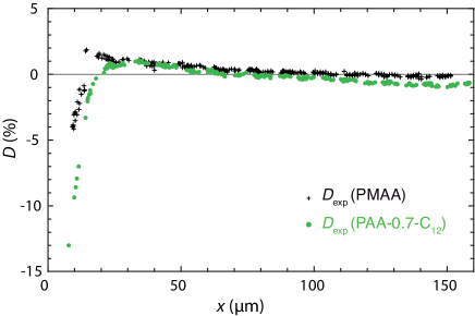
The case of the PMAA monolayers (Figure 3(a)) was already presented and analyzed theoretically in a previous article 35. In this case, the deformation quickly becomes positive at the constriction exit because of the elongational flow and then relaxes toward zero when the elongational stress decreases.
In the case of the monolayers of PAA--C12, the deformation initially negative becomes positive, reaches a maximum, before becoming negative again (Figure 3(a)), unlike the PMAA monolayers.
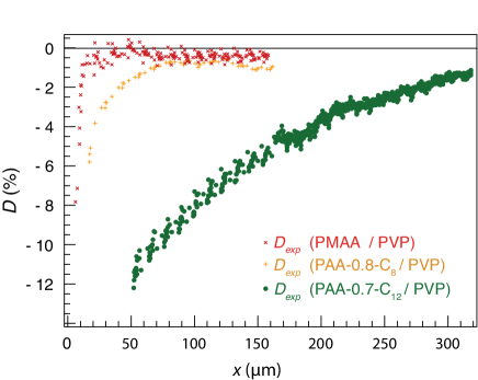
We observe more pronounced qualitative differences for the two other types of membrane, as shown in Figure 3(b): the deformation remains negative all along the trajectory and shows no maximum for the bilayers PMAA/PVP, PAA--C12/PVP and PAA--C8/PVP. In addition, we observe that PAA--C12/PVP capsules relax significantly more slowly than all the other systems.
3.2 Theoretical Analysis
3.2.1 Capillary model
In a given flow field, a droplet adopts a steady deformation, which was shown by Barthès-Biesel et al. 45 to depend on the viscosity ratio between the droplet and the surrounding phase , the radius of the droplet , and the interfacial tension between the two phases as follows45 :
| (2) |
where and are the eigenvalues of the deformation-rate tensor.
The same authors also described the transient regime leading to this steady deformation as a first-order relaxation in time 45. The derivative of the deformation with respect to time thus depends on the steady deformation and the actual deformation, through:
| (3) |
with a relaxation time defined as follows 45:
| (4) |
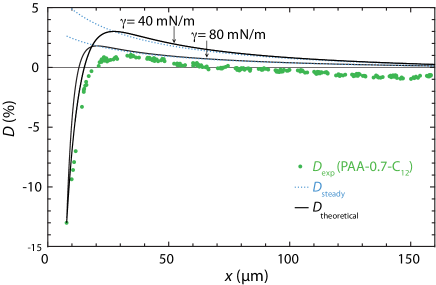
We showed in our previous article that this model fits well the data obtained for the PMAA monolayer droplets35. However, as shown in Figure 4, this simple capillary model can not fit the data obtained for the PAA--C12 capsules. More precisely, this model predicts that the deformation reaches positive values before returning to zero deformation. However the PAA--C12 returns to negative deformations at longer times. For the same reasons, the bilayer cases presented in Figure 3(b) can not be properly fitted (not shown) by the capillary model as they do not reach positive values of deformation. This means that, except for PMAA monolayers, our capsules cannot be considered as simple droplets with a homogeneous and constant interfacial tension.
However, we have several evidences that a capillary model is probably not sufficient to describe such membranes. Indeed, measuring the interfacial tension of PAA--C12 layers using the pendant-drop method and varying the area of the drops (by deflating them), we found 40 that the surface tension decreases as the area decreases, similarly to the case of interfaces with insoluble surfactants 46. It is likely that the surface tension is not constant and homogeneous at the droplet interface as it is deformed. Such a membrane can be described by a surface dilational elastic modulus: 47.
In the case of the PMAA/PVP, we found that these bilayers exhibit both shear and dilational moduli on the order of the surface tension value according to pendant-drop and shear-rheometer experiments39.
In order to take into account these considerations, we alternatively consider these membranes as purely elastic ones.
3.2.2 Elastic model
In the case of purely elastic membranes, i.e. in the absence of capillary effects and membrane viscosity, Barthes-Biesel and Rallison 27 proposed a model to describe the relaxation of a slightly deformed capsule toward its spherical shape. In such a case, the exponentional relaxation occurs in a steady liquid and is driven by the elasticity of the membrane, while the bulk viscosity of the droplet tends to slow down the dynamics. In a more general case, the deformation relaxes toward a reference deformation following the equation:
| (5) |
where the introduced time scale can take the two (note the possible signs) following values:
| (6) |
with the 2D shear elastic modulus (homogeneous to an energy per unit surface) of the membrane. In the simplest case, =0 and the capsules relax toward a spherical shape. As pointed out by Leclerc et al. 36, the largest relaxation time rules the relaxation of the membrane which is then given by: .
Note that, using the same characteristic time, a variant of Equation (5) has been recently proposed by Gires et al. 38 for viscoelastic membranes, which also does not take into account the extensional flow (but only the shear flow).
Such models, by neglecting the extensional flow, can only predict a relaxation of the capsules from a negative deformation to a spherical shape and cannot account for a positive deformation as the one observed for PAA--C12.
3.2.3 Suggested model
To account for all our experimental results, we suggest that both the interfacial tension and the elasticity of the membrane should be taken into account. The deformation should result from two contributions.
The first one comes from the competition between the shear rate in the continuous phase which deforms the capsule and the surface tension which resists the deformation. This competition can be described dynamically by Equation (3).
The second contribution corresponds to an elastic relaxation toward a reference shape , which is not necessarily zero. Such a dynamic is described by Equation (5).
As previously mentioned, we point out that our membranes can be considered as elastic. Moreover, variations of the surface tension due to surface-excess variations are usually taken into the elastic effects together with the actual elasticity of the membrane. Both components contribute to the restoring forces and are defined by a global 2D effective modulus (homogeneous to an energy per unit surface).
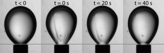
Furthermore, we know thanks to interfacial rheology experiments that the polymer membranes do relax: the surface tension rises after compression and decreases after dilatation (not shown), and the shape of droplets covered by such membranes evolves over time after compression of the interface, as shown in Figure 5. This means that the polymer chains in the membrane relax. At short time scales, the shape of the capsule should thus be a compromise between the initial shape (minimizing the energy for the elastic membrane that matured in the narrow channel) and the spherical shape (minimizing the area and hence the energy due to the homogeneous and isotropic surface tension). At long time scales, the membrane being viscoelastic, the polymer chains and thus the elastic stresses should relax and the droplet should retrieve its spherical shape. To include this potential membrane relaxation in our model, we allow for to be a function of time that relaxes towards zero over a viscoelastic polymeric time .
The initial reference deformation is thus comprised between (i.e. the spherical shape of the droplet before the narrow channel) and the deformation of the capsule in the narrow channel, depending on the length of the latter and thus the maturation of the confined membrane. Figure 6 illustrates the case where the narrow channel is long enough to have the restoring stresses totally relaxed before the capsule enters the wide chamber. In such a case, the reference deformation at the entrance of the wide chamber matches the actual deformation at that point.
In our experiments, the capsules are confined in the narrow channel during a time . The long-channel approximation is thus valid if , which has to be checked a posteriori.
We would like here to insist on the distinction between the time and the two other times and . The two latter times describe the relaxation of the capsule’s shape according to a competition between a driving force (interfacial tension or elasticity) and the bulk viscosity. On the contrary, describes the relaxation of the stresses within the membrane, and is thus related to the relaxation of the constitutive polymer chains which is the core of the membrane’s viscoelasticity. The typical length scales associated to these two types of processes are thus totally different: and describe the capsule as an object of a few tens of micrometers, while describe the dynamics of the polymer chains, whose size is on the order of a few tens of nanometers. Accordingly, we expect to be independent of the capsule’s radius , while we know from Equations (4) and (6) that and scale linearly with .
To summarize, inspired by the pure cases above, we propose a more general model that simply assumes a superimposition of all the different contributions, and that couples them through the following equations (valid in the large chamber only):
| (7a) | |||||
| (7b) |
The first term of the right-hand side of Equation (7a) comes from Equation (3). It corresponds to a capillary relaxation towards an instantaneous steady state, and it is characterized by the time scale . The second term corresponds to an elastic relaxation towards an instantaneous reference state, and it is characterized by the time scale which includes the effects of different moduli: the “liquid modulus" describing the variations of the surface tension due to surface-excess variations, the 2D elastic compression modulus , and the 2D elastic shear modulus . We note the 2D effective modulus which is a combination of these three moduli, and that is expected to be close to the highest of these three moduli. We can thus write that:
| (8) |
Equation (7b) accounts for the relaxation of the stresses in the membrane, and the viscoleastic return to a spherical shape. We would like to point out that a long relaxation time of the polymers usually implies a high modulus in simple systems: for instance in the Lucassen model 46, a long relaxation time is due to a low diffusivity. This implies a high value of the liquid modulus . Such systems would elastically relax over a short time . In more complex systems, the link between and can be less straightforward. This is in particular what we will see in the following.
Solving the above coupled equations allows to predict a theoretical deformation of the capsules, with an interfacial tension and viscoelastic effects, in a viscous extensional flow. They will be confronted to the experimental data presented above, which will provide three fitting parameters, , and , and thus insights on the various mechanisms at play.
Finally, as a remark, we can recast Equation (7a) into an effective single-forcing process:
| (9) |
where:
| (10) |
and:
| (11) |
This compact form highlights the universality of the model, that could be extended to other types of responses: more complex viscoelasticity, charge effects, poroelasticity…
3.2.4 PAA--C12 monolayer: quickly-relaxing low modulus
We use the general model presented in Equation (7b) to fit the experimental data for the PAA--C12 capsules. The fit shown in Figure 7 provides: (i.e. an interfacial tension of ), , and .
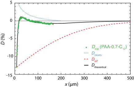
Pendant-drop experiments for an oil-water interface (not shown) indicated that the interfacial tension between mineral oil and PAA--C12 is about and decreases under compression. Here, we find an interfacial tension that is higher than in pendant-drop experiments, but we have a fair order-of-magnitude agreement. Moreover, we observe that , which we interpret as follows: the interfacial-tension variations (i.e the liquid modulus) are low compared to the absolute value of the interfacial tension but not completely negligible. Finally, we find that , which validates the long-channel approximation discussed above: at the end of the narrow channel, just before the capsules enter the wide chamber, all the elastic stresses have relaxed. Thus, the inital reference deformation corresponds to the actual shape of the capsules as they enter the chamber.
3.2.5 PAA--C12/PVP bilayer: slowly-relaxing high modulus
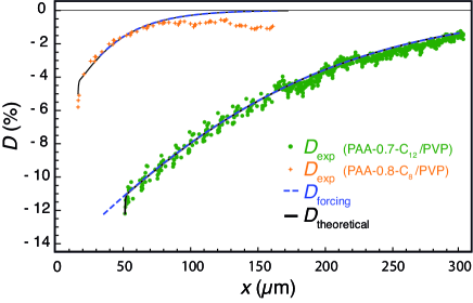
We apply the same analysis to the capsules covered by a PAA--C12/PVP bilayer, as presented in Figure 8. The best fit gives , and thus (we recall here that also depends on the capsule’s radius, which slightly varies between the different experiments) the same interfacial tension () as for the PAA--C12 monolayer. Moreover, we find the same polymeric relaxation time () as in the case of the PAA--C12 monolayer, but a significantly lower elastic time . According to Equation (8), this implies that the effective elastic modulus is significantly higher for the bilayer than for the monolayer, which is consistent with the added interactions between PAA--C12 and PVP chains.
The value obtained for the polymeric relaxation time () is also coherent with the pendant-drop experiments reported previously 39. Therein, there was no evidence of any surface-tension inhomogeneity, or anisotropy, during compression, neither for the PAA--C12/PVP bilayers nor for the PAA--C12 monolayers, which indicates that the inner relaxation times are shorter than the typical time scale of such experiments (on the order of ).
Furthermore, we interpret the concordance of the polymer relaxation time between the monolayer and the bilayer as a consequence of the predominance of the alkyle graft anchoring on the dynamics of the interface, as shown in a previous work 39. A second evidence for the importance of graft anchoring is the comparison with an analogous experiment performed on PAA--C8/PVP bilayers, also presented in Figure 8. We observe that the relaxation of such bilayers is much faster than the relaxation of PAA--C12/PVP bilayers. In this simple picture, shorter alkyle grafts, and thus lower anchoring energy, leads to faster relaxation. In such a case, if the relaxation of the bilayers was instead controlled by the moduli only (and thus ), we would expect a lower elastic modulus for the PAA--C8 compared to the PAA--C12 as these chains are less strongly anchored to the interface48. In such case, according to Equation (8), we would observe a faster relaxation for PAA--C12/PVP than for PAA--C8/PVP – which is opposite to what we measured. This comparison between PAA--C8/PVP and PAA--C12/PVP thus indicates that the relaxation time which rules the overall relaxation of those capsules is the one for polymer relaxation , and that graft anchoring is a key factor of the underlying polymer dynamics.
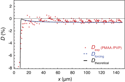
3.2.6 PMAA/PVP bilayer: barely-relaxing high modulus
Unlike the PAA--C12/PVP bilayers, the PMAA/PVP bilayers show wrinkles during several seconds after compression in pendant-drop experiments, as presented in Figure 5. Accordingly, we expect to have in this case , which has two implications. First, this time scale is much longer than the time during which the capsules are confined in the narrow channel . As a consequence, we assume that such capsules do not have enough time to undergo any viscoelastic maturation process within the narrow channel, and that the reference deformation at the entrance of the wide chamber is close to zero (because of the memory of the non-deformed state before confinement). Secondly, the expected value of is so high that it can be considered as infinite when compared to the typical time scales of our microfluidic measurements, which is about . Therefore, we fix the value of the reference deformation to a (almost zero) constant at all times.
The result of the fit is presented in Figure 9. We find the same interfacial tension as for the PMAA monolayer 35, and an elastic time similar to the elastic time of PAA--C12/PVP.
3.3 Discussion
We summarize in Table 1 all the results obtained by fitting the experiments to the general model. The effective 2D moduli are calculated from according to Equation (6).
| PMAA 35 | |||||
|---|---|---|---|---|---|
| PAA--C12 | |||||
| PAA--C12/PVP | |||||
| PAA--C8/PVP | |||||
| PMAA/PVP |
The orders of magnitude of the obtained moduli are in fair agreement with what we expect from macroscopic measurements, when available. In the case of PAA--C12, where the modulus is a liquid dilational modulus , if there is no desorption, we can show that , where is the surface pressure appearing in the state equation of Leclerc et al. 49 (cf Supplementary Information). The surface pressure of PAA--C12 at the mineral oil-water interface is , which leads to , in good agreement with what we obtained in our experiments. For the PAA--C12/PVP bilayer, no measurement of the elastic modulus has been performed at time scales smaller than , and consequently we have no reference for comparison. In contrast, the value extracted from the experiment with PMAA/PVP is close to the value measured in the interfacial rheometer 5, 39.
In summary, the general model described in Equation (7b) offers both a good understanding of the relaxation dynamics of various capsules in a microfluidic device, and a satisfactory agreement with calibrated experiments concerning the extracted physical parameters. The strong influence of the ratio between the polymer and confinement time scales (which e.g. controls the differences observed between the PAA--C12/PVP and PMAA/PVP systems) further suggests that it might be interesting to perform new sets of experiments by varying the length of the narrow channel. This would be a way to extract more precisely , and to characterize further the underlying molecular mechanisms for relaxation – a key ingredient for understanding and tuning finely the membrane properties.
4 Conclusion
Through the use of a sharp microfluidic-channel extension we measured the shape relaxation of capsules with different kinds of polymer membranes. We observed various behaviors depending of the viscoelastic parameters of these membranes. We proposed a general model to understand this rich set of behaviors, arising from the relative importances of the outer fluid viscosity, and the interfacial tension, elastic modulus, and/or viscous modulus of the membranes. The comparison of the experiments with the model predictions allows us to rationalize all the experimental results in a unified framework. Based on this work, by screening different confinement times, we envision the possibility of probing finely, and in situ, the rheological and molecular behaviours of capsules and cells within microfluidic plateforms.
Acknowledgements
This work was financially supported by ANR JCJC INTERPOL. The authors thank Mamisoa Nomena and Samuel Poincloux for their precious help and advice in this work. They also thank Oliver Bäumchen, Ingmar Polenz, Jean-Christophe Baret, Julien Dupré de Baubigny, Nadège Pantoustier and Patrick Perrin for fruitful discussions.
References
- 1 U. Klinkesorn, P. Sophanodora, P. Chinachoti, E. A. Decker, and D.J. McClements. Encapsulation of emulsified tuna oil in two-layered interfacial membranes prepared using electrostatic layer-by-layer deposition. Food Hydrocolloids, 19(6):1044–1053, 2005.
- 2 M. Delcea, H. Mohwald, and A. G. Skirtach. Stimuli-responsive LbL capsules and nanoshells for drug delivery. Advanced Drug Delivery Reviews, 63(9):730–747, 2011.
- 3 S. Correa, K. Y. Choi, E. C. Dreaden, K. Renggli, A. Shi, L. Gu, K. E. Shopsowitz, M. A. Quadir, E. Ben-Akiva, and P. T. Hammond. Highly Scalable, Closed-Loop Synthesis of Drug-Loaded, Layer-by-Layer Nanoparticles. Advanced Functional Materials, 26(7):991–1003, 2016.
- 4 J. Yang, M. W. Keller, J. S. Moore, S. R. White, and N. R. Sottos. Microencapsulation of isocyanates for self-healing polymers. Macromolecules, 41(24):9650–9655, 2008.
- 5 S. Le Tirilly, C. Trégouët, S. Bone, C. Geffroy, G. Fuller, N. Pantoustier, P. Perrin, and C. Monteux. Interplay of Hydrogen Bonding and Hydrophobic Interactions to Control the Mechanical Properties of Polymer Multilayers at the Oil/Water Interface. ACS Macro Letters, 4(1):25–29, 2014.
- 6 C. Gao, S. Leporatti, S. Moya, E. Donath, and H. Möhwald. Stability and Mechanical Properties of Polyelectrolyte Capsules Obtained by Stepwise Assembly of Poly(styrenesulfonate sodium salt) and Poly(diallyldimethyl ammonium) Chloride onto Melamine Resin Particles. Langmuir, 17(11):3491–3495, 2001.
- 7 A. A. Antipov and G. B. Sukhorukov. Sustained release properties of polyelectrolyte multilayer capsules. The Journal of Physical Chemistry B, 105:2281–2284, 2001.
- 8 C. Priest, A. Quinn, A. Postma, A. N. Zelikin, J. Ralston, and F. Caruso. Microfluidic polymer multilayer adsorption on liquid crystal droplets for microcapsule synthesis. Lab on a chip, 8(12):2182–2187, 2008.
- 9 C. Kantak, S. Beyer, L. Yobas, T. Bansal, and D. Trau. A ’microfluidic pinball’ for on-chip generation of Layer-by-Layer polyelectrolyte microcapsules. Lab on a chip, 11(6):1030–5, 2011.
- 10 P. Erni. Deformation modes of complex fluid interfaces. Soft Matter, 7:7586–7600, 2011.
- 11 I. Polenz, D. A. Weitz, and J.-C. Baret. Polyurea microcapsules in microfluidics: Surfactant control of soft membranes. Langmuir, 31(3):1127–1134, 2015.
- 12 M. Bjornmalm, A. Roozmand, K.F. Noi, J. Guo, J. Cui, J. J. Richardson, and F. Caruso. Flow-Based Assembly of Layer-by-Layer Capsules through Tangential Flow Filtration. Langmuir, 31(33):9054–60, 2015.
- 13 J. Dupré de Baubigny, C. Trégouët, T. Salez, N. Pantoustier, P. Perrin, M. Reyssat, and C. Monteux. One-Step Fabrication of pH-Responsive Membranes and Microcapsules through Interfacial H-Bond Polymer Complexation. Scientific Reports, 7(1):1265, 2017.
- 14 S. Vandebril, A. Franck, G. G. Fuller, P. Moldenaers, and J. Vermant. A double wall-ring geometry for interfacial shear rheometry. Rheologica Acta, 49(2):131–144, 2009.
- 15 B. Sarrazin, N. Tsapis, L. Mousnier, N. Taulier, W. Urbach, and P. Guenoun. AFM Investigation of Liquid-Filled Polymer Microcapsules Elasticity. Langmuir, 32(18):4610–4618, 2016.
- 16 K. Xie, C. de Loubens, F. Dubreuil, D. Z. Gunes, M. Jaeger, and M. Leonetti. Interfacial rheological properties of self-assembling biopolymer microcapsules. Soft Matter, 13:6208–6217, 2017.
- 17 S. Knoche, D. Vella, E. Aumaitre, P. Degen, H. Rehage, P. Cicuta, and J. Kierfeld. Elastometry of deflated capsules: Elastic moduli from shape and wrinkle analysis. Langmuir, 29(40):12463–12471, 2013.
- 18 O. Oshri, F. Brau, and H. Diamant. Wrinkles and folds in a fluid-supported sheet of finite size. Physical Review E - Statistical, Nonlinear, and Soft Matter Physics, 91(5):1–13, 2015.
- 19 V. D Gordon, X. Chen, J. W. Hutchinson, A. R. Bausch, M. Marquez, and D. A. Weitz. Self-assembled polymer membrane capsules inflated by osmotic pressure. Journal of the American Chemical Society, 126(43):14117–22, 2004.
- 20 D. Carvajal, E. J. Laprade, K. J. Henderson, and K. R. Shull. Mechanics of pendant drops and axisymmetric membranes. Soft Matter, 7(22):10508, 2011.
- 21 P. Erni, H. A. Jerri, K. Wong, and A. Parker. Interfacial viscoelasticity controls buckling, wrinkling and arrest in emulsion drops undergoing mass transfer. Soft Matter, 8(26):2958, 2012.
- 22 J. K. Ferri, P. A. L. Fernandes, J. T. McRuiz, and F. Gambinossi. Elastic nanomembrane metrology at fluid-fluid interfaces using axisymmetric drop shape analysis with anisotropic surface tensions: deviations from Young-Laplace equation. Soft Matter, 8(40):10352, 2012.
- 23 R. M. Kleinberger, N.A. Burke, K. Dalnoki-Veress, and H. D. Stöver. Systematic study of alginate-based microcapsules by micropipette aspiration and confocal fluorescence microscopy. Materials science & engineering. C, Materials for biological applications, 33(7):4295–304, 2013.
- 24 A. Walter, H. Rehage, and H. Leonhard. Shear induced deformation of microcapsules: shape oscillations and membrane folding. Colloids and Surfaces A: Physicochemical and Engineering Aspects, 183:123–132, 2001.
- 25 M. Prevot, A. L. Cordeiro, G. B. Sukhorukov, Y. Lvov, R. S. Besser, and H. Möhwald. Design of a Microfluidic System to Investigate the Mechanical Properties of Layer-by-Layer Fabricated Capsules. Macromolecular Materials and Engineering, 288(12):915–919, 2003.
- 26 X.-Q. Hu, B. Sévénié, A.-V. Salsac, E. Leclerc, and D. Barthès-Biesel. Characterizing the membrane properties of capsules flowing in a square-section microfluidic channel: Effects of the membrane constitutive law. Physical Review E, 87(6):063008, 2013.
- 27 D. Barthès-Biesel and J. M. Rallison. The time-dependent deformation of a capsule freely suspended in a linear shear flow. Journal of Fluid Mechanics, 113:251–267, 1981.
- 28 R Finken, S Kessler, and U Seifert. Micro-capsules in shear flow. Journal of Physics: Condensed Matter, 23(18):184113, 2011.
- 29 M. Higley, M. Siegel, and M. R. Booty. Semi-analytical solutions for two-dimensional elastic capsules in Stokes flow. Proceedings of the Royal Society A: Mathematical, Physical and Engineering Sciences, 468(2146):2915–2938, 2012.
- 30 C. Pozrikidis. Finite deformation of liquid capsules enclosed by elastic membranes in simple shear flow. Journal of Fluid Mechanics, 297:123, 1995.
- 31 S.-Y. Park and P. Dimitrakopoulos. Transient dynamics of an elastic capsule in a microfluidic constriction. Soft Matter, 9(37):8844, 2013.
- 32 A. Koolivand and P. Dimitrakopoulos. Deformation of an elastic capsule in a microfluidic T-junction: settling shape and moduli determination. Microfluidics and Nanofluidics, 21(5):1–12, 2017.
- 33 G. I. Taylor. The Formation of Emulsions in Definable Fields of Flow. Proceedings of the Royal Society A: Mathematical, Physical and Engineering Sciences, 146(858):501–523, 1934.
- 34 J. T. Cabral and S. D. Hudson. Microfluidic approach for rapid multicomponent interfacial tensiometry. Lab on a chip, 6(3):427–436, 2006.
- 35 C. Trégouët, T. Salez, C. Monteux, and M. Reyssat. Transient deformation of a droplet near a microfluidic constriction : a quantitative analysis. Physical Review Fluids, 3:053603, 2018.
- 36 E. Leclerc, H. Kinoshita, T. Fujii, and D. Barthès-Biesel. Transient flow of microcapsules through convergent-divergent microchannels. Microfluidics and Nanofluidics, 12(5):761–770, 2011.
- 37 I. Polenz, Q. Brosseau, and J.-C. Baret. Monitoring reactive microencapsulation dynamics using microfluidics. Soft matter, 11:2916–2923, 2015.
- 38 P.-Y. Gires, D. Barthès-Biesel, E. Leclerc, and A.-V. Salsac. Transient behavior and relaxation of microcapsules with a cross-linked human serum albumin membrane. Journal of the Mechanical Behavior of Biomedical Materials, 58:2–10, 2016.
- 39 S. Le Tirilly, C. Trégouët, M. Reyssat, S. Bône, C. Geffroy, G. Fuller, N. Pantoustier, P. Perrin, and C. Monteux. Interfacial Rheology of Hydrogen-Bonded Polymer Multilayers Assembled at Liquid Interfaces: Influence of Anchoring Energy and Hydrophobic Interactions. Langmuir, 32(24):6089–6096, 2016.
- 40 C. Tregouët. Polymer multilayers at liquid interfaces : assembly , interfacial rheology and microfluidic probing. PhD thesis, Université Pierre et Marie Curie, 2016.
- 41 K. T. Wang, I. Iliopoulos, and R. Audebert. Viscometric behaviour of hydrophobically modified poly(sodium acrylate). Polymer Bulletin, 20:577–582, 1988.
- 42 D. Bartolo, G. Degre, P. Nghe, and V. Studer. Microfluidic stickers. Lab on a Chip-Miniaturisation for Chemistry and Biology, 8(2):274–279, 2008.
- 43 M. Yamada, M. Nakashima, and M. Seki. Pinched flow fractionation: Continuous size separation of particles utilizing a laminar flow profile in a pinched microchannel. Analytical Chemistry, 76(18):5465–5471, 2004.
- 44 Y. Rotenberg, L. Boruvka, and A. W. Neumann. Determination of surface tension and contact angle from the shapes of axisymmetric fluid interfaces. Journal of Colloid And Interface Science, 93(1):169–183, 1983.
- 45 D. Barthès-Biesel and A. Acrivos. Deformation and burst of a liquid droplet freely suspended in a linear shear field. Journal of Fluid Mechanics, 61:1–22, 1973.
- 46 J. Lucassen and M. Van Den Tempel. Dynamic measurements of dilational properties of a liquid interface. Chemical Engineering Science, 27(6):1283–1291, 1972.
- 47 E. H. Lucassen-Reynders, A. Cagna, and Lucassen J. Gibbs elasticity, surface dilational modulus and diffusional relaxation in nonionic surfactant monolayers. Colloids and Surfaces A: Physicochemical and Engineering Aspects, 186(1):63 – 72, 2001.
- 48 C. Barentin, P. Muller, and J. F. Joanny. Polymer Brushes Formed by End-Capped Poly(ethylene oxide) (PEO) at the Air-Water Interface. Macromolecules, 31:2198–2211, 1998.
- 49 E. Leclerc, R. Douillard, M. Daoud, and V. Aguie-Beghin. Asymmetric Multiblock Copolymers at the Gas - Liquid Interface : Phase Diagram and Surface Pressure. Journal of Colloid and Interface Science, 155(2):143–155, 1999.