Sub-Hertz Optomechanically-Induced Transparency
Abstract
Optical interferometers with suspended mirrors are the archetype of all current audio-frequency gravitational-wave detectors. The radiation pressure interaction between the motion of the mirror and the circulating optical field in such interferometers represents a pristine form of light-matter coupling, largely due to 30 years of effort in developing high quality optical materials with low mechanical dissipation. However, in all current suspended interferometers, the radiation pressure interaction is too weak to be useful as a resource, and too strong to be neglected as a noise source. Here, we demonstrate a meter-long interferometer with suspended mirrors of effective mass , where the radiation pressure interaction is enhanced by strong optical pumping to realize a cooperativity of . We probe this regime by observing optomechanically-induced transparency of a weak on-resonant probe. The low resonant frequency and high-Q of the mechanical oscillator allows us to demonstrate transparency windows barely wide at room temperature. Together with a near-unity () out-coupling efficiency, our system saturates the theoretical delay-bandwidth product, rendering it an optical buffer capable of seconds-long storage times.
Interferometers with suspended end-mirror cavities are one of today’s most sensitive instruments LIGO Scientific Collaboration and Virgo Collaboration (2016). Suspending the optics isolate them from technical noises of seismic and anthropic origin. Once classical noises are mitigated, the sensitivity of the interferometer increases with the intensity of the optical field circulating within. However, high-power operation is limited by classical and quantum mechanical effects of radiation pressure Braginsky and Manukin (1967); Braginsky (1968); Caves (1980). The longitudinal motion of the suspended end-mirror, considered as a harmonic oscillator, is susceptible to two effects arising from the coupling between its motion and the circulating optical field. Classically, a radiation pressure force that depends on the oscillator position – due to feedback from the optical (cavity) delay – can lead to parametric instability Corbitt et al. (2006); Evans et al. (2015). Quantum mechanically, the fluctuations in the number of photons recoiling off of the end-mirror – quantum radiation pressure noise – can perturb the oscillator Purdy et al. (2013); Wilson et al. (2015); Teufel et al. (2016); Cripe et al. (2018). Whilst the former effect can be described as a modification of the susceptibility of the oscillating mirror due to its coupling to the optical field, the latter is a fluctuating force originating from the same coupling. Generally it can be shown that the two effects scale identically with power Clerk et al. (2010). This scaling is described by the dimensionless radiation pressure coupling strength, quantified by the cooperativity (to be defined below). At present in Advanced LIGO, the radiation pressure coupling between a higher order mechanical mode and transverse optical mode has been shown to be strong enough () to initiate parametric instability Evans et al. (2015), yet weak enough that quantum radiation pressure noise is buried tantalizingly beneath technical noises LIGO Scientific Collaboration and Virgo Collaboration (2016); LSC Instrument Authors et al. (2017).
Here we demonstrate a suspended-mirror interferometer with a radiation pressure cooperativity an order of magnitude larger () than what has previously been directly observed in such an instrument Corbitt et al. (2006); Miyakawa et al. (2006); Corbitt et al. (2007a, b); Evans et al. (2015). In contrast to nano-fabricated optomechanical systems Aspelmeyer et al. (2012, 2014), our system consists of a mechanical oscillator of effective mass – 9 orders of magnitude more massive – susceptible to the recoil-type radiation pressure coupling, and an interferometer that is formed by a 1m long suspended cavity, both of which make it a mock-up of an Advanced LIGO arm. This system serves as a general experimental platform for audio-band optomechanics in a radiation-pressure-dominated regime Corbitt et al. (2006, 2007a, 2007b).
The basic challenge of operating such an interferometer in the high cooperativity regime is the ability to store enough photons in the cavity to amplify the radiation pressure force without destabilizing it by other means. In order to retain sufficient photons in the cavity with practical input laser powers, it is necessary that the end mirrors’ optical losses – already at a state-of-the art level of a few parts per million (ppm) – be diluted by elongating the cavity. Operating a long cavity with suspended mirrors introduces additional challenges that must be overcome. In particular, maintaining alignment requires seismic isolation whose fundamental suspension mode is low frequency (). Thermal noise requirements demand the suspending fibers be thin. Thus, the suspensions are necessarily “soft”, and their torsional modes are susceptible to a radiation-pressure torque instability Solimeno et al. (1991); Sidles and Sigg (2006) – an effect that has been a limiting factor in the high power operation of suspended interferometers Hirose et al. (2010); Sakata et al. (2010); Dooley et al. (2013). On the one hand, the magnitude of the resonant round-trip gain for the radiation-pressure-induced longitudinal coupling between cavity frequency and length is the cooperativity,
| (1) |
where , is the optomechanical coupling rate for an end-mirror of effective mass , oscillating at frequency , which leads to a cavity frequency fluctuation for a cavity of length and decay rate , loaded with photons on average. On the other hand, the gain for the torque coupling scales as , where is the moment of inertia Sidles and Sigg (2006). The ratio of the round-trip gains of the two processes (longitudinal and torsional radiation pressure) scale as – heavier mirrors reduce the susceptibility to radiation pressure force, while longer cavities enhance the effect of radiation pressure torque.
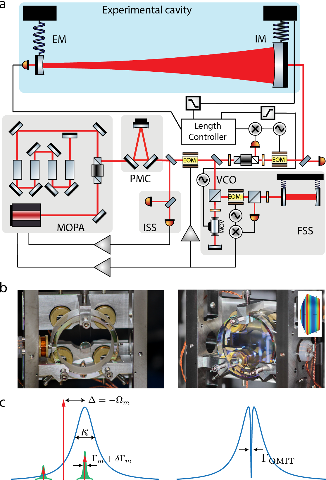
The competing demands of being radiation pressure dominated longitudinally while still maintaining angular stability are met in our experimental system, depicted in Figure 1. The optical cavity of interest is formed by two mirrors – an end mirror (EM) weighing with a transmission of 3 ppm, and an input mirror (IM) weighing with a transmission 800 ppm – suspended on pendulums placed apart (this gives a cavity of linewidth ). In order to suppress extraneous beam-pointing noise, the experiment is mounted on an actively damped seismic vibration isolation platform, similar to the one used in Advanced LIGO Matichard et al. (2015), which attenuates ground motion to a level of above a few Hz. The cavity is driven by laser light from a master-oscillator power amplifier (MOPA) capable of delivering 10 W of continuous output at 1064 nm Abbott and King (1999). Extraneous power fluctuations are reduced to a relative intensity noise of above 100 Hz; this, together with carefully centering of the beam position on the mirrors (by minimizing the transduction of the suspension pitch mode onto the phase of the light leaking out of the cavity), reduces torque fluctuations to insignificant levels. The spatial mode of the laser is cleaned by passing it through a pre-mode cleaner, so as to prevent extraneous signals from higher order modes in the quadrant photodetectors (not shown in figure) that are used to feedback-stabilize cavity alignment. The laser is frequency-stabilized to an independent reference cavity. In this configuration, optical torque instabilities are not expected to limit high power operation, and it should be possible to realize .
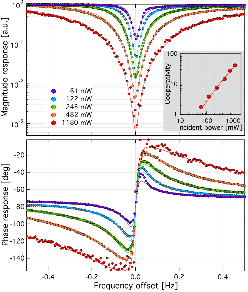
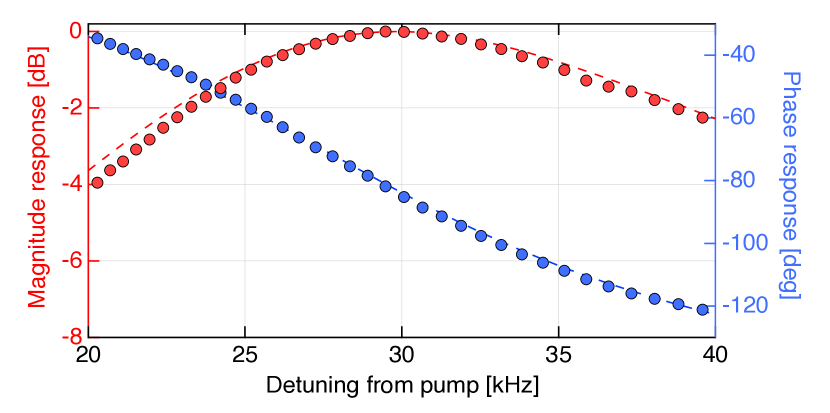
Exploiting the slew of technical capabilities originally developed for LIGO, we observe optomechanically-induced transparency (OMIT) Agarwal and Huang (2010); Weis et al. (2010); Safavi-Naeini et al. (2011); Teufel et al. (2011); Xiong and Wu (2018) due to the coupling between the drumhead mode of the IM (see fig. 1b) and the intracavity field. Modulating the incident laser at a variable frequency offset from its carrier creates an intracavity radiation pressure at the same frequency. When , the drumhead mode is resonantly excited by this intracavity radiation pressure force; this displacement gets transduced as phase-modulation sidebands back on the intracavity field, which can interfere with the injected modulation sideband. When the carrier is detuned from the cavity resonance by the mechanical frequency (i.e. ), the interference is perfectly destructive. In the experiment we probe the cavity response from within the feedback loop used to stabilize its length. First, we acquire lock of the cavity length to the laser by using a Pound-Drever-Hall signal in reflection (see fig. 1a); we then hand over the length control from the reflection signal to the transmission signal in order to be able to red-detune by . The cavity response is then probed by frequency-modulation sidebands generated by dithering the frequency servo error point, and demodulating the signal out of the photodetector in transmission. We verify the detuning by fits to the broadband response of the cavity (see sup ). Finally, we measure the response in the vicinity of the cavity resonance in a high-resolution scan to observe the narrow OMIT feature. However, the response observed in this manner needs to be corrected for the response of the frequency stabilization loop through which both the probe and the measurement are made (see sup for details). Figure 2 shows the magnitude and phase of this corrected response as the power in the incident laser is increased. The gross features of the cavity transmission can be understood from the approximate model sup ,
| (2) |
where, , is the cavity transmission without any optomechanical coupling, and , is the optically-damped contribution to the mechanical decay rate; here is the effective cooperativity taking into account the finite sideband resolution , which gives, . The bare cavity transmission is a Lorentzian of width , while the second factor describes an OMIT window of width given by the effective mechanical linewidth, on cavity resonance. As the cooperativity increases, . The expression in eq. 25 is however an approximation that disregards the finite sideband resolution; in fact, it only describes the contribution to the transmitted photodetector signal that arises from the upper-sideband of the intracavity field. A full model accounting for both sidebands is shown as the fits in fig. 2 (see sup for the full model). These fits allow us to extract the cooperativity, shown as the inset in the figure. At the highest incident power of 1.2 W, we realize .
Our results of mHz demonstrate the narrowest OMIT windows yet observed (a recent experiment at dilution refrigerator temperature is comparable Yuan et al. (2015)). This is largely due to the ability to operate an optomechanical system in the high-cooperativity regime using a mechanical oscillator with a long decay time. We achieve this by using a low frequency oscillator featuring a high intrinsic mechanical quality factor of , consistent with expectations for bulk fused silica Startin et al. (1998); Numata et al. (2004).
The sub-hertz OMIT feature is beneficial for various applications ranging from frequency-agile ultra-narrow filter cavities Ma et al. (2014), to coherent frequency converters Tian and Wang (2010); Hill et al. (2012), to slow-light optical buffers Tucker et al. (2005) and quantum memories. In the following we discuss the potential of our system as a highly efficient slow-light buffer capable of seconds-long delays. An optical buffer for coherent classical signals is characterized by the maximum possible delay that it can provide, and the usable bandwidth; they are not independent for passive systems, and in fact the delay-bandwidth product (DBP) is bounded Tucker et al. (2005); Khurgin (2005); Miller (2007); Baba (2008); Thevenaz (2008). Further, if the buffer also features a near-unity storage and retrieval efficiency, it may be used to store weak incoherent classical signals. In the limit that the signal is encoded in a pure quantum state – as required for various quantum information processing tasks – the optical buffer becomes a quantum memory Lvovsky et al. (2009); Afzelius et al. (2015), if in addition to the above requirements, it also features a coherence time longer than the storage time.
In the case of OMIT, the group delay, , where is the phase response, is explicitly given by,
| (3) |
It is negative (advance) or positive (delay) depending on whether the signal sideband is transmitted or reflected Weis et al. (2010); Safavi-Naeini et al. (2011); Karuza et al. (2013). Note that is the efficiency of the reflection port, given by the fractional contribution of the input mirror decay rate to the total cavity decay rate. From the measured phase response, we are able to extract the delay in transmission and reflection, shown in the inset of fig. 3. The inferred absolute delays, in the range of several (tens of) seconds, are more than an order of magnitude larger than what has previously been demonstrated using an optomechanical system Karuza et al. (2013), and approaching what has been demonstrated using atomic EIT Heinze et al. (2013). Further, the signal efficiency in our system is near-ideal (), largely due to the pristine optical quality, and significantly exceeds prior demonstrations of OMIT and even atomic EIT Schraft et al. (2016).

Finally, the combination of long delays, and near-ideal coupling efficiency, allows for a delay-bandwidth product (DBP) that is very large. From eq. 3, the DBP is given by,
| (4) |
The DBP takes a maximum value of for readout in reflection. Figure 3 shows that our system saturates this upper bound, which is also comparable with what is in principle achievable with atomic EIT systems Khurgin (2005); Tucker et al. (2005). The potential of our system as a quantum memory is currently limited by the decoherence time of the mechanical mode (), and the associated thermal noise. Recent work has demonstrated record low-noise quantum memory using an intracavity Raman medium to suppress nonlinear mixing processes Saunders et al. (2016), however at the expense of efficiency. In principle, optomechanical systems with macroscopic oscillators and low-loss mirrors can be free of optical and mechanical nonlinearities – respectively of the Duffing and thermal types – while preserving optical efficiency. With further improvements employing recently demonstrated techniques for mechanical Q enhancement Tsaturyan et al. (2017); Ghadimi et al. (2018), it is conceivable that the regime of quantum coherent mechanical oscillation (, where is the average thermal phonon occupation of the oscillator) can be achieved even in a suspended-optic interferometer. In conjunction with adiabatically varying the pump amplitude Fleischhauer and Lukin (2000); Tian (2012), a long-lived on-demand OMIT-based quantum memory may be realized.
The combination of high cooperativity and ideal out-coupling efficiency are also the same requirements for using radiation pressure quantum fluctuations as a useful metrological resource in an interferometer Sudhir et al. (2017). At the moment, the cooperativity we achieve is limited by a new source of angular instability. Our observations are consistent with the conjecture that surface roughness on the cavity mirror leads to scattering of the cavity’s fundamental mode into a few higher order modes, which causes radiation pressure torques. With mitigation of this problem we expect the current system to be a testbed for studying and reducing the effects of quantum noise on a suspended interferometer with macroscopic test masses.
Acknowledgements. This work was supported by the National Science Foundation via grants PHY-1707840 and PHY-1404245. VS is supported by the Swiss National Science Foundation fellowship grant P2ELP2_178231. We also gratefully acknowledge Eric Oelker and our colleagues in the LIGO Scientific Collaboration for valuable interactions. This paper has LIGO Document Number LIGO-P1800358.
References
- LIGO Scientific Collaboration and Virgo Collaboration (2016) LIGO Scientific Collaboration and Virgo Collaboration, Phys. Rev. Lett. 116, 131103 (2016).
- Braginsky and Manukin (1967) V. Braginsky and A. Manukin, Sov. Phys. JETP 25, 653 (1967).
- Braginsky (1968) V. B. Braginsky, Sov. Phys. JETP 26, 831 (1968).
- Caves (1980) C. Caves, Phys. Rev. Lett. 45, 75 (1980).
- Corbitt et al. (2006) T. Corbitt, D. Ottaway, E. Innerhofer, J. Pelc, and N. Mavalvala, Phys. Rev. A 74, 021802 (2006).
- Evans et al. (2015) M. Evans et al., Phys. Rev. Lett. 114, 161102 (2015).
- Purdy et al. (2013) T. P. Purdy, R. W. Peterson, and C. A. Regal, Science 339, 801 (2013).
- Wilson et al. (2015) D. J. Wilson, V. Sudhir, N. Piro, R. Schilling, A. Ghadimi, and T. J. Kippenberg, Nature 524, 325 (2015).
- Teufel et al. (2016) J. Teufel, F. Lecocq, and R. Simmonds, Phys. Rev. Lett. 116, 013602 (2016).
- Cripe et al. (2018) J. Cripe, N. Aggarwal, R. Lanza, A. Libson, R. Singh, P. Heu, D. Follman, G. Cole, N. Mavalvala, and T. Corbitt, arXiv:1802.10069 (2018).
- Clerk et al. (2010) A. A. Clerk, M. H. Devoret, S. M. Girvin, F. Marquardt, and R. J. Schoelkopf, Rev. Mod. Phys. 82, 1155 (2010).
- LSC Instrument Authors et al. (2017) LSC Instrument Authors, D. V. Martynov, et al., Phys. Rev. A 95, 043831 (2017).
- Miyakawa et al. (2006) O. Miyakawa, R. Ward, R. Adhikari, M. Evans, B. Abbott, R. Bork, D. Busby, J. Heefner, A. Ivanov, M. Smith, R. Taylor, S. Vass, A. Weinstein, M. Varvella, S. Kawamura, F. Kawazoe, S. Sakata, and C. Mow-Lowry, Phys. Rev. D 74, 022001 (2006).
- Corbitt et al. (2007a) T. Corbitt, Y. Chen, E. Innerhofer, H. Müller-Ebhardt, D. Ottaway, H. Rehbein, D. Sigg, S. Whitcomb, C. Wipf, and N. Mavalvala, Phys. Rev. Lett. 98, 11 (2007a).
- Corbitt et al. (2007b) T. Corbitt, C. Wipf, T. Bodiya, D. Ottaway, D. Sigg, N. Smith, S. Whitcomb, and N. Mavalvala, Phys. Rev. Lett. 99, 160801 (2007b).
- Aspelmeyer et al. (2012) M. Aspelmeyer, P. Meystre, and K. Schwab, Physics Today 65, 29 (2012).
- Aspelmeyer et al. (2014) M. Aspelmeyer, T. J. Kippenberg, and F. Marquardt, Rev. Mod. Phys. 86, 1391 (2014).
- Solimeno et al. (1991) S. Solimeno, F. Barone, C. de Lisio, L. Di Fiore, L. Milano, and G. Russo, Phys. Rev. A 43, 6227 (1991).
- Sidles and Sigg (2006) J. A. Sidles and D. Sigg, Physics Letters A 354, 167 (2006).
- Hirose et al. (2010) E. Hirose, K. Kawabe, D. Sigg, R. Adhikari, and P. R. Saulson, Applied Optics 49, 3474 (2010).
- Sakata et al. (2010) S. Sakata, O. Miyakawa, A. Nishizawa, H. Ishizaki, and S. Kawamura, Phys. Rev. D 81, 064023 (2010).
- Dooley et al. (2013) K. L. Dooley, L. Barsotti, R. X. Adhikari, M. Evans, T. Fricke, P. Fritschel, V. Frolov, K. Kawabe, and N. D. Smith-Lefebvre, JOSA A 30, 2618 (2013).
- Matichard et al. (2015) F. Matichard et al., Classical and Quantum Gravity 32, 185003 (2015).
- Abbott and King (1999) R. Abbott and P. King, Pre-stabilized Laser Final Design Document, Tech. Rep. T990025 (LIGO, 1999).
- Agarwal and Huang (2010) G. S. Agarwal and S. Huang, Phys. Rev. A 81, 041803 (2010).
- Weis et al. (2010) S. Weis, R. Riviere, S. Deléglise, E. Gavartin, O. Arcizet, A. Schliesser, and T. J. Kippenberg, Science 330, 1520 (2010).
- Safavi-Naeini et al. (2011) A. H. Safavi-Naeini, T. P. M. Alegre, J. Chan, M. Eichenfield, M. Winger, Q. Lin, J. T. Hill, D. E. Chang, and O. Painter, Nature 472, 69 (2011).
- Teufel et al. (2011) J. D. Teufel, D. Li, M. S. Allman, K. Cicak, A. J. Sirois, J. D. Whittaker, and R. W. Simmonds, Nature 471, 204 (2011).
- Xiong and Wu (2018) H. Xiong and Y. Wu, Appl. Phys. Rev. 5, 031305 (2018).
- (30) Supplementary Information.
- Yuan et al. (2015) M. Yuan, V. Singh, Y. M. Blanter, and G. A. Steele, Nature Communications 6, 8491 (2015).
- Startin et al. (1998) W. Startin, M. Beilby, and P. Saulson, Rev. Sci. Instru. 69, 3681 (1998).
- Numata et al. (2004) K. Numata, K. Yamamoto, H. Ishimoto, S. Otsuka, K. Kawabe, M. Ando, and K. Tsubono, Phys. Lett. A 327, 263 (2004).
- Ma et al. (2014) Y. Ma, S. L. Danilishin, C. Zhao, H. Miao, W. Z. Korth, Y. Chen, R. L. Ward, and D. G. Blair, Phys. Rev. Lett. 113, 151102 (2014).
- Tian and Wang (2010) L. Tian and H. Wang, Phys. Rev. A 82, 053806 (2010).
- Hill et al. (2012) J. T. Hill, A. H. Safavi-Naeini, J. Chan, and O. Painter, Nature Communications 3, 1196 (2012).
- Tucker et al. (2005) R. S. Tucker, P.-C. Ku, and C. J. Chang-Hasnain, J. Lightwave Tech. 23, 4046 (2005).
- Khurgin (2005) J. Khurgin, JOSA B 22, 1062 (2005).
- Miller (2007) D. Miller, Phys. Rev. Lett. 99, 203903 (2007).
- Baba (2008) T. Baba, Nature Photonics 2, 465 (2008).
- Thevenaz (2008) L. Thevenaz, Nature Photonics 2, 474 (2008).
- Lvovsky et al. (2009) A. I. Lvovsky, B. C. Sanders, and W. Tittel, Nature Photonics 3, 706 (2009).
- Afzelius et al. (2015) M. Afzelius, N. Gisin, and H. de Riedmatten, Physics Today 68, 42 (2015).
- Karuza et al. (2013) M. Karuza, C. Biancofiore, M. Bawaj, C. Molinelli, M. Galassi, R. Natali, P. Tombesi, G. Di Giuseppe, and D. Vitali, Phys. Rev. A 88, 013804 (2013).
- Heinze et al. (2013) G. Heinze, C. Hubrich, and T. Halfman, Physical Review Letters 111, 033601 (2013).
- Schraft et al. (2016) D. Schraft, M. Hain, N. Lorenz, and T. Halfman, Physical Review Letters 116, 073602 (2016).
- Saunders et al. (2016) D. Saunders, J. Munns, T. Champion, C. Qiu, K. Kaczmarek, E. Poem, P. Ledingham, I. Walmsley, and J. Nunn, Phys. Rev. Lett. 116, 090501 (2016).
- Tsaturyan et al. (2017) Y. Tsaturyan, A. Barg, E. S. Polzik, and A. Schliesser, Nature Nanotechnology 12, 776 (2017).
- Ghadimi et al. (2018) A. H. Ghadimi, S. A. Fedorov, N. J. Engelsen, M. J. Bereyhi, R. Schilling, D. J. Wilson, and T. J. Kippenberg, Science 360, 764 (2018).
- Fleischhauer and Lukin (2000) M. Fleischhauer and M. Lukin, Phys. Rev. Lett. 84, 5094 (2000).
- Tian (2012) L. Tian, Phys. Rev. Lett. 108, 153604 (2012).
- Sudhir et al. (2017) V. Sudhir, R. Schilling, S. Fedorov, H. Schütz, D. Wilson, and T. Kippenberg, Phys. Rev. X 7, 031055 (2017).
- Gardiner et al. (1987) C. W. Gardiner, A. S. Parkins, and M. J. Collett, JOSA B 4, 1617 (1987).
- Zhou et al. (2013) X. Zhou, F. Hocke, A. Schliesser, A. Marx, H. Huebl, R. Gross, and T. J. Kippenberg, Nature Physics 9, 179 (2013).
- Sigg (2009) D. Sigg, Common Mode Servo Board, Tech. Rep. LIGO-D040180 (LIGO, 2009).
Supplementary Information
I Theoretical model for OMIT
In the following we recapitulate the model used to interpret the OMIT data presented in Figure 2 of the main manuscript. The presentation largely follows the standard treatment adopted in the cavity optomechanics community Weis et al. (2010); Safavi-Naeini et al. (2011).
The basic optomechanical Hamiltonian that describes the radiation pressure interaction between the cavity field (), end-mirror displacement (), and the driving laser field () is Aspelmeyer et al. (2014)
| (5) |
where,
| bare cavity resonance frequency | |
|---|---|
| bare optomechanical coupling strength | |
| displacement and momentum of the oscillator | |
| effective mass of oscillator | |
| frequency of oscillator | |
| input laser field (in units of ) | |
| cavity loss rate through IM/EM | |
| ; – IM/EM transmission |
The Heisenberg equations that follow from eq. 5 are,
| (6) |
where is the mechanical decay rate, and is the total loss rate of the cavity including from the EM, any internal loss, and the IM. Note that since the mechanical oscillator is high-Q (), and since we are only interested in its response near resonance, we have adopted a velocity-damped model for its loss. Further, since we are interested in the driven response of the system, optical and mechanical input noises are omitted.
The input field that drives the cavity () is derived from a laser oscillating at with sidebands imprinted on it; it is thus described by,
| (7) |
When eq. 7 is substituted into the equation of motion in eq. 6, we arrive at a set of coupled nonlinear equations that describe the full radiation pressure optomechanical dynamics which features a static optical bistability and static spring shifts of the mechanical oscillator. In the regime where the carrier flux is fixed and much larger than the sideband, i.e. , these equations can be linearized about a given operating point. These linearized equations, expressed in the frame rotating at the laser frequency , take the form,
| (8) |
Here, we have defined an effective detuning,
that contains the bare laser-cavity detuning (first term) and a term due to the static cavity frequency shift from radiation pressure coupling; is the static mirror displacement, while
| (9) |
is the mean intracavity field amplitude; and are the fluctuations on top of these mean values. (Note that we have omitted the phase of the intracavity field in eq. 8 with the understanding that it is a constant offset from the phase of the input laser for fixed detuning.) It is convenient to express eq. 9 in terms of the incident power, , and the mean intracavity photon number, , as,
| (10) |
where we have defined, , the cavity coupling efficiency from the incident port. Henceforth we will redefine for notational convenience; further, we take to be real by absorbing its (frequency-independent) phase, , into the input, with the understanding that such static phase shifts are irrelevant in our measurement.
The OMIT phenomena entails a modification of the cavity response via its radiation pressure interaction with the end mirror. In the experiment, we measure the magnitude and phase of this modified response at frequency offsets from the incident pump laser, using probe sidebands at these frequencies, described by,
| (11) |
where are the amplitudes of the upper and lower sideband, respectively; since the sidebands are imprinted by phase modulation,
| (12) |
Such a drive produces intracavity fields and oscillator displacements at the same frequency since the equations of motion eq. 8 are linear. In order to track these we introduce the ansatz,
| (13) |
into eq. 8, and separate out terms oscillating at the two sideband frequencies; this gives the closed set of coupled equations:
| (14) |
where we have defined the optical and mechanical susceptibilities,
| (15) |
Note that in going to eq. 14, we have approximated the mechanical susceptibility using a single-pole response,
which is effectively a rotating-wave approximation valid in the high-Q limit, .
Solving eq. 14 for the mechanical motion excited by the intracavity field,
| (16) |
where, the effective mechanical susceptibility,
| (17) |
describes the radiation pressure modification of the mechanical response, whose strength scales with the optomechanical coupling rate, . When optomechanical coupling is weak enough to not lead to normal-mode splitting (i.e. when ), the effective mechanical susceptibility can be approximated in terms of a modified mechanical linewidth (optical damping) and resonance frequency (optical spring), viz.,
where and are identified by separating the real and imaginary parts of the second term in eq. 17. We are interested in these expressions for the case of red-sideband pumping, i.e. ; in this case,
| (18) |
where,
| (19) |
is the optomechanical cooperativity, which quantifies the fractional effect of the radiation-pressure modification of the mechanical susceptibility. Note that in our case, characterized by , the optical spring is weak for red-sideband pumping, and we henceforth neglect . The oscillator response is thus described by featuring a modified linewidth.
The effect of the modified oscillator is to scatter phase-modulation sidebands on the intracavity field, which can then interfere with the sidebands already present from the modulation imprinted on the incident field. The resulting intracavity field can be obtained by inserting eq. 16 back into eq. 14 and solving for , viz.,
| (20) |
where,
| (21) |
In writing these expression, we have used the fact that the input laser is phase-modulated. Note that in the absence of optomechanical coupling (i.e., ), , and eq. 20 simply describes the cavity response filtering the incident field. The effect of optomechanical coupling is captured by the factor – featuring the shape of the modified mechanical susceptibility – which is superimposed on top of the (relatively) slowly varying cavity response. It is this superimposed feature that manifests as an optomechanically-induced transparency window. Note that as the optomechanical coupling is increased by strong pumping, , we have on resonance, , leading to complete transparency.
The experimentally observed fields are the ones leaking out of the cavity, either in transmission, or reflection. The transmitted and reflected fields are Gardiner et al. (1987),
| (22) |
where, , is the intracavity field in the rotating frame of the input laser. In the following we focus on the transmitted field, with the understanding that the reflected field can be computed similarly. Using eqs. 20, 12 and 9 in eq. 22, the transmitted field is,
| (23) |
where, , is the modulation index. The first term in parenthesis describes the portion of the input pump that is transmitted, while the second and third terms describe the upper and lower sidebands respectively. Eq. (2) of the main text is just the second term, describing the transmission of the upper sideband alone. However, due to the finite sideband resolution of our system, a sizable fraction, , of the lower sideband is also transmitted. In our experiment, where the pump is red-detuned () and at Fourier frequencies close to mechanical resonance (), this ratio is, .
When the transmitted field is detected on a photodetector, the detector output voltage is ; in the experiment we detect the voltage that is phase-coherent with the input modulation. We are thus interested in the in-phase and quadrature-phase components of the voltage oscillating at . This oscillating component is,
| (24) |
Note that here we have omitted the phase of which is a frequency-independent phase offset. The final line in eq. 24 implicitly separates out the in-phase and quadrature-phase components of the photodetector signal measured by the network analyzer; the complex response – the measured cavity transmission coefficient – is then . Explicitly computing this gives,
| (25) |
which can be understood as the upper sideband contribution diminished by the undesired lower sideband transmitted by the cavity. This is the full model used to fit the data in the main text. The reflection coefficient can be calculated in a similar fashion.
I.1 Delay, bandwidth, and their product
Both the cavity outputs, transmission and reflection, feature the conventional cavity response on top of which is superimposed the OMIT feature described by . The former varies in frequency over a scale given by the cavity FWHM , while the latter varies within a much smaller interval, which can be read off from eq. 21 to be the modified mechanical linewidth . Thus the bandwidth of the OMIT feature is,
| (26) |
where we have defined the effective cooperativity,
| (27) |
that characterizes the efficacy of dynamical radiation pressure effects for a system with finite sideband resolution. In the limit of infinite sideband resolution, i.e. , we have , and the expression for reduces to the one in the literature Weis et al. (2010); Safavi-Naeini et al. (2011); Teufel et al. (2011); Zhou et al. (2013).
The delay experienced by the probe depends on whether it is detected in transmission or reflection. When detected in transmission, the resonant group delay is given by,
Evaluating this, using the expression for the transmission coefficient (eq. 25) and the expression for (eq. 21), we get,
| (28) |
where the first term is the delay due to the effect of the bare cavity, while the second term is from OMIT. Since (in the weak-coupling regime we operate in), we can safely neglect the first term.
When detected in reflection, as in the case of single-port cavities Weis et al. (2010); Safavi-Naeini et al. (2011); Teufel et al. (2011); Zhou et al. (2013), the group delay is affected by the out-coupling efficiency. To wit,
| (29) |
The delay-bandwidth product (DBP),
| (30) |
is thus different when the probe is measured in transmission or reflection. In fact,
| (31) |
Note that when the out-coupling efficiency through the reflection port is ideal (), .
II Experimental details
II.1 Calibration of OMIT response
In the experiment, both the excitation to probe the cavity and the readout, are done inside the frequency stabilization servo loop, as shown in Figure 4. In order to isolate the OMIT response it is necessary to measure and calibrate out the responses of the other elements of the loop.
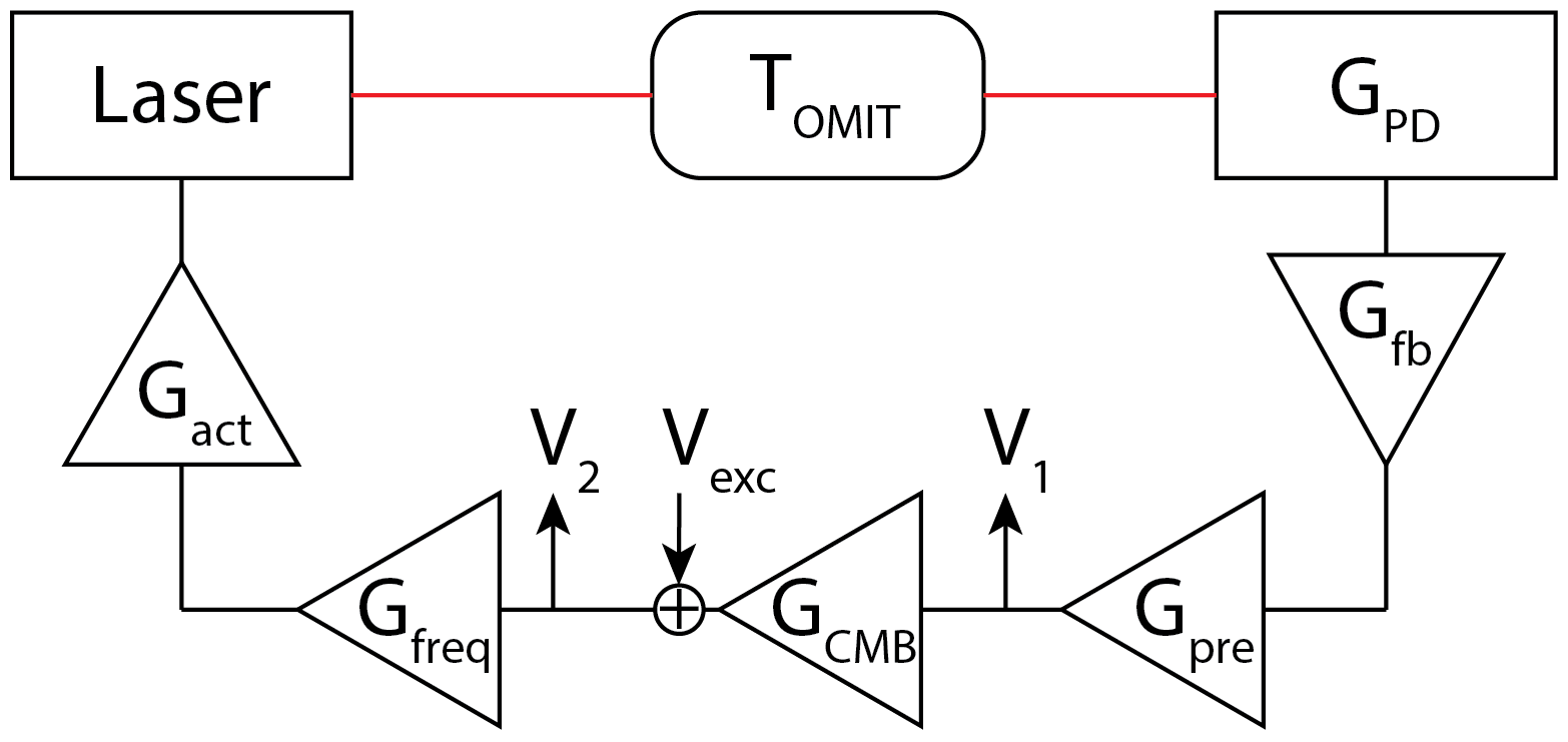
In the experiment, a network analyzer (SR785) is used to apply a stimulus at the input of the “common-mode board” (CMB) – a custom-built configurable electronic hardware Sigg (2009) used as the length control servo here – which causes the laser frequency to modulate via the FSS (frequency stabilization servo) loop. This modulation is incident on the cavity, essentially sensing the OMIT response , and gets detected at a photodiode (with response ). The resulting signal is processed via an analog loop filter with response and a pre-amplifier (SR560) with response . A part of the output () is detected phase coherently with the excitation using the network analyzer, while the rest is passed onto the CMB (with response ). A part of the CMB’s output is also picked off after being summed with the excitation () to be independently detected using the same network analyzer. This loop is shown in Figure 4.
We use the network analyzer to measure the response (vis-a-vis the ratio of the two response measurements and ). From the loop diagram we can understand how to disentangle the information we need – the OMIT response – from this measurement. Going around the loop diagram we find for V1:
which implies,
| (32) |
where, is the open-loop gain of the loop.
Performing a similar calculation for gives,
| (33) |
| (34) |
and so,
| (35) |
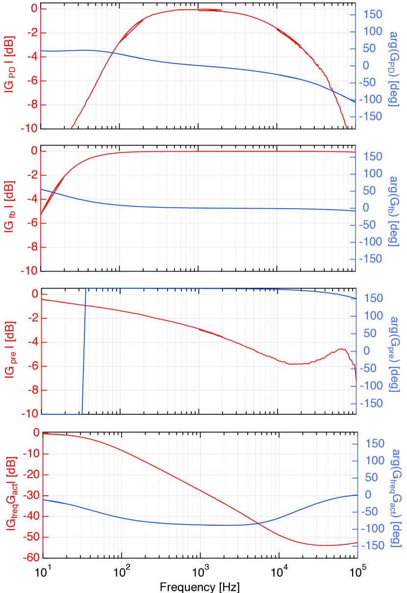
Figure 5 shows the measured responses that are used in conjunction with eq. 35 to infer the OMIT response. Note that we are interested in the shape of the OMIT response, and not its absolute magnitude which can be established from the independently measured broadband cavity transmission (shown in fig. 6); thus the measured responses in fig. 5 omit overall dimensions for .
II.2 Data analysis
After the data has been corrected, we adopt the following procedure to extract the relevant optomechanical parameters. The broadband cavity response, such as the one shown in fig. 6, is used to infer the detuning and the total cavity linewidth . Using these values, we then fit the narrowband cavity response, containing the OMIT feature, to extract the mechanical frequency , its effective linewidth , and effective mass , while the bare optomechanical coupling is assumed. The fits to the data at each value of the incident power gives the following estimates for the various parameters:
| kHz | |
|---|---|
| mHz | |
| kHz | |
| gm | |