Nonreciprocal transmission and fast-slow light effects
in a cavity optomechanical system
Abstract
We study the nonreciprocal transmission and the fast-slow light effects in a cavity optomechanical system, in which the cavity supports a clockwise and a counter-clockwise circulating optical modes, both the two modes are driven simultaneously by a strong pump field and a weak signal field. We find that when the intrinsic photon loss of the cavity is equal to the external coupling loss of the cavity, the system reveals a nonreciprocal transmission of the signal fields. However, when the intrinsic photon loss is much less than the external coupling loss, the nonreciprocity about the transmission properties almost disappears, and the nonreciprocity is shown in the group delay properties of the signal fields, and the system exhibits a nonreciprocal fast-slow light propagation phenomenon.
pacs:
(270.0270) Quantum optics; (120.4880) Optomechanics; (230.0230) Optical devices.I Introduction
In recent years, optical nonreciprocity has got a lot of attentions for its important applications in photonic network, signal processing, and one-way optical communication protocols. In the common nonreciprocal devices, such as, isolator, circulator, nonreciprocal phase shifter, the transmission of the information is not symmetric. At present, the researches about the optical nonreciprocity mainly focused on two aspects: one is the transmission properties of the signal fields, another is the photonic statistical properties of the signal fields.
For the first aspect, scientists have demonstrated that many physical effects and physical systems, such as Faraday rotation effect in the magneto-optical crystals 1 ; 2 ; 3 , optical nonlinearity 4 , spatial-symmetry-breaking structures 5 ; 6 , optoacoustic effects 7 ; 8 , the parity-time-symmetric structures 9 ; 10 ; 11 ; 12 , can be used to realize the optical nonreciprocal transmission. Efforts have also been made to study the nonreciprocal transmission in cavity optomechanical systems 13 ; 14 ; 15 ; 16 ; 17 . Manipatruni et al. demonstrated that the optical nonreciprocal transmission was based on the momentum difference between the forward and backward-moving light beams in a Fabry-Perot cavity with one moveable mirror 18 . Hafezi et al. proposed a scheme to achieve the nonreciprocal transmission in a microring resonator by using an unidirectional optical pump 19 . Metelmann and Clerk discussed a general method for nonreciprocal photon transmission and amplification via reservoir engineering 20 . Peterson et al. demonstrated an efficient frequency-converting microwave isolator based on the optomechanical interactions 21 . Mirza et al. studied the optical nonreciprocity and slow light propagation in coupled spinning optomechanical resonators 22 .
For the second aspect, the researches on the photonic statistic properties of the transmitted fields in nonreciprocal devices are fewer. At present, the relevant theoretical works include the nonreciprocal photon blockade 23 , the authors discussed how to create and manipulate nonclassical light via photon blockade in rotating nonlinear devices. They found that the light with sub-Poissonian or super-Poissonian photon-number statistics can emerge when driving the resonator from its left or right side. Subsequently, Xu et al. proposed a scheme to manipulate the statistic properties of the photons transport nonreciprocally via quadratic optomechanical coupling 24 .
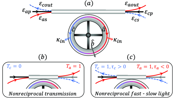
In this paper, we study the nonreciprocal transmission and the fast-slow light effects in a cavity optomechanical system, as shown in Fig. 1. We show that when the intrinsic photon loss of the cavity equals the external coupling loss of the cavity, we can achieve the nonreciprocal transmission of the signal fields with the red-sideband pumping or the blue-sideband pumping. We also show that when the intrinsic photon loss is much less than the external coupling loss, the nonreciprocity of the system about the optical transmission properties almost disappears, now the system exhibits a nonreciprocal fast-slow light propagation phenomenon, i.e., the group velocity of the right-moving signal field will be speed up (fast light), while the group velocity of the left-moving signal field will be slowed down (slow light), or vice versa.
II Model and Hamiltonian
Our system model is shown in Fig. 1(a). We consider an optomechanical microtoroid cavity, which supports a clockwise circulating mode () and a counter-clockwise circulating mode (), both the two cavity modes couple with the mechanical mode () via the radiation pressure. The cavity mode () is driven simultaneously by a strong pump field () and a weak signal field (). The total Hamiltonian of the system can be expressed as
| (1) |
where is the Hamiltonian of the cavity optomechanical system. and are the annihilation operators of the clockwise (counter clockwise) circulating cavity mode and the mechanical mode with frequency and , respectively. is the optomechanical coupling strength between the cavity modes and the mechanical mode. describes the interactions of the cavity mode with the pump field of amplitude and the signal field of amplitude , respectively, in which is the coupling decay rate of the cavity, and () is the laser power. Similarly, describes the interaction Hamiltonian of cavity mode with the pump field of amplitude and the signal field of amplitude , respectively. The last term represents the interaction between the two cavity modes with the strength .
For simplicity, we assume that the two pump fields have the same frequency, i.e., . In the rotation frame with , the system Hamiltonian can be written as
| (2) | |||||
where is the frequency detuning between the cavity field () and the pump field (, ), and () is the frequency detuning between the signal field () and the pump field (). The system dynamics is fully described by the set of quantum Heisenberg-Langevin equations
| (3) |
where the cavity has the damping rate , which are assumed to be due to the intrinsic photon loss and external coupling loss, respectively, and the mechanical mode has the damping rate . (), and are the -correlated operators of the input noises for the cavity mode () and the mechanical mode , respectively. These noise operators satisfy .
In this model, we are interested in the mean response of the system. Thus, in the following, we turn to calculate the evolutions of the expectation values of , , , and we denote , , , , , . By using the mean-field assumption , we can write the equations for the mean values as
| (4) |
Equations (4) can be solved by using the perturbation method in the limit of the strong pump fields, while taking the signal fields to be weak. Using the linearization approximation, we make the following ansatz 25
| (5) | |||||
where can be any one of the quantities , , , or their complex conjugates , , . represents the steady-state mean value of the corresponding system mode, and , , , are the additional fluctuations. By substituting Eq. (5) into Eqs. (4), and keeping only the first-order in the small quantities and neglecting the nonlinear terms like , , , , we can obtain the steady-state mean value equations, and the fluctuation equations for the cavity mode components and (see the appendix). By solving these equations, we find that , , the concrete forms of the coefficients and are tediously long, and we will not write them out here.
The relation among the input, internal, and output fields is given as 26 . By using the ansatz again, we write the output field as . Then we can obtain the output field components and . The transmissivities can be written as , . The nonreciprocal transmission is then described by the normalized transmissivities (transmission spectra)
| (6) |
What’s more, in the resonant region of the transmission spectra, the output signal fields have the phase dispersions and , which can cause the group delay 27
| (7) |
The group delay corresponds to the slow light propagation of the signal field, and the group delay corresponds to the fast light propagation of the signal field. In the following, we will discuss the nonreciprocal transmission (, or , ) and the nonreciprocal fast-slow light effects (, or , ), respectively.
In this paper, the parameters are chosen based on the recently experiment28 ; 29 : MHz and Hz (quality factor ), the equivalent mass of the mechanical resonance ng, and the equivalent cavity length mm. The damping rate of the optical cavity MHz, the wavelength of the pump laser nm. The other parameters are Hz, MHz.
III Nonreciprocal transmission
In this section, we numerically evaluate the transmission spectra and to show the possibility of achieving the nonreciprocal transmission of the signal fields.
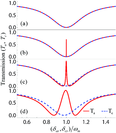
Firstly, we assume that the system works near the red sideband (). In Fig. 2 we plot and as a function of and , respectively. Here we hold the pump power constant, nW 30 . We can see that the transmission of the left-moving signal field is simply that of a bare resonator, and exhibits a dip near (). By adjusting the pump power , we find that the transmission of the right-moving signal field can be obviously modified. Near , will exhibit a very narrow peak and gradually increase with the increase of . When , we have . If we continue to increase , the spectrum will exhibit a split, and this is associated with the normal mode splitting 31 . The above features can result in a nonreciprocal transmission of the signal fields in our system, i.e., the right-moving signal field is completely transmitted, while the left-moving signal field is blocking-up.
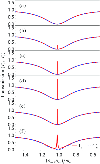
Then we consider that the system works near the blue sideband (), and we also choose nW. In Fig. 3, we can see that exhibits a dip near (). By adjusting the pump power , will exhibit a very narrow peak near , with the increase of , the peak value will first increase and then decrease. When , we have , , now the right-moving signal field can be amplified, while the left-moving signal field cannot be amplified. When , we have , . Now the system can also be used to realize the nonreciprocal transmission of the signal fields.
In addition, in our system, the transmissive direction of the signal field can be changed by adjusting the ratio of and . For example, when , nW and , now the left-moving signal field is completely transmitted while the right-moving signal field is blocking-up.
IV Nonreciprocal fast-slow light effects
In this section, we show how to realize the nonreciprocal fast-slow light propagation of the signal fields, i.e., both the right-moving and left-moving signal fields can be completely transmitted, while the group velocity of the right-moving signal field will be speed up and the left-moving signal field will be slowed down, or vice versa.
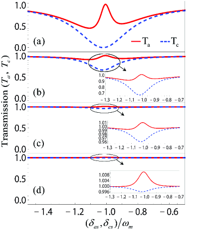
In Fig. 4, we plot and for different intrinsic photon loss rate under the unbalanced-pumping condition (, nW). We find that with the decrease of the transmission of the left-moving signal field will gradually increase near . However, the transmission of the right-moving signal field near . When , we have , , now the nonreciprocity of the system about the optical transmission is weakened. When , we have , , and the nonreciprocity of the system about the optical transmission almost disappears(().
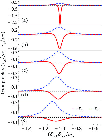
However, in this situation (), the nonreciprocity of system is shown in the group delay properties of the signal fields. In Fig. 5, we plot and as a function of and , respectively. We can see that in the range of the parameters we considered (we have plotted the transmission spectra and and we can guarantee that for all the parameters used in Fig. 5), the group delay of the right-moving signal field is negative near (the group velocity will be speed up), that corresponds to the fast light propagation. While the group delay of the left-moving signal field is positive near (the group velocity will be slowed down), that corresponds to the slow light propagation. This shows that the system can exhibit a nonreciprocal fast-slow light propagation of the signal fields.
Furthermore, we can change the propagation direction of the fast-slow light by adjusting the ratio of of and . For example, in Fig. 5(c), we have and . However, if we choose nW and , then we have and , now the right-moving signal field is slow light and the left-moving signal field is fast light.
V Conclusion
In summary, we have studied the nonreciprocal transmission and the fast-slow light effects in a cavity optomechanical system. We have shown that for both the red-sideband pumping or the blue-sideband pumping, the system can act as an optical unidirectional isolator. We have also shown that if the intrinsic photon loss is much less than the external coupling loss, the nonreciprocity of the system on the optical transmission almost disappears, now the system reveals an interesting nonreciprocal fast-slow light propagation phenomenon. Our proposed model might have applications in the photonic network.
Fundings. This work was supported by the National Natural Science Foundation of China (Nos. 11574092, 61775062, 61378012, 91121023); the National Basic Research Program of China (No. 2013CB921804).
Appendix
By substituting Eq. (5) into Eqs. (4), we can obtain the the steady-state mean value equations
| (A1) |
In this system, we are interested on the dynamics of the cavity mode components and which are resonance with the corresponding signal fields and , respectively. We can obtain
| (A2) | ||||
| (A3) |
where and , .
References
- (1) R. L. Espinola, T. Izuhara, M. C. Tsai, R. M. Osgood Jr, and H. Dötsch, “Magneto-optical nonreciprocal phase shift in garnet/silicon-on-insulator waveguides,” Opt. Lett. 29, 941 (2004).
- (2) M. Levy, “Nanomagnetic route to bias-magnet-free on-chip faraday rotators,” J. Opt. Soc. Am. B 22, 254 (2005).
- (3) T. R. Zaman, X. Guo, and R. J. Ram, “Faraday rotation in an InP waveguide,” App. Phys. Lett. 90, 023514 (2007).
- (4) X. Guo, C. L. Zou, H. Jung, and H. X. Tang, “On-chip strong coupling and efficient frequency conversion between telecom and visible optical modes,” Phys. Rev. Lett. 117, 123902 (2016).
- (5) C. Wang, C. Zhou, and Z. Li, “On-chip optical diode based on silicon photonic crystal heterojunctions,” Opt. Express 19, 26948 (2011).
- (6) K. Xia, M. Alamri, and M. S. Zubairy, “Ultrabroadband nonreciprocal transverse energy flow of light in linear passive photonic circuits,” Opt. Express 21, 25619 (2013).
- (7) Q. Wang, F. Xu, Z. Y. Yu, X. S. Qian, X. K. Hu, Y. Q. Lu, and H. T. Wang, “A bidirectional tunable optical diode based on periodically poled LiNbO3,” Opt. Express 18, 7340 (2010).
- (8) M. S. Kang, A. Butsch, and P. S. J. Russell, “Reconfigurable light-driven opto-acoustic isolators in photonic crystal fibre,” Nat. Photonics 5, 549 (2011).
- (9) C. Eüter, K. G. Makris, R. EI-Ganainy, D. N. Christodoulides, M. Segev, and D. Kip, “Observation of parity-time symmetry in optics,” Nat. Phys. 6, 192 (2010).
- (10) H. Ramezani, T. Kottos, R. El-Ganainy, and D. N. Christodoulides, “Unidirectional nonlinear PT-symmetric optical structures,” Phys. Rev. A 82, 043803 (2010).
- (11) L. Feng, M. Ayache, J. Q. Huang, Y. L. Xu, M. H. Lu, Y. F. Chen, Y. Fainman, and A. Scherer, “Nonreciprocal light propagation in a silicon photonic circuit,” Science 333, 729 (2011).
- (12) J. H. Wu, M. Artoni, and G. C. La Rocca, “Non-Hermitian degeneracies and unidirectional reflectionless atomic lattices,” Phys. Rev. Lett. 113, 123004 (2014).
- (13) X. W. Xu and Y. Li, “Optical nonreciprocity and optomechanical circulator in three-mode optomechanical systems,” Phys. Rev. A 91, 053854 (2015).
- (14) L. Tian and Z. Li, “Nonreciprocal quantum-state conversion between microwave and optical photons,” Phys. Rev. A 96, 013808 (2017).
- (15) S. Barzanjeh, M. Wulf, M. Peruzzo, M. Kalaee, P. B. Dieterle, O. Painter, and J. M. Fink, “Mechanical on-chip microwave circulator,” Nat. Commun. 8, 953 (2017).
- (16) D. Malz, L. D. Tóth, N. R. Bernier, A. K. Feofanov, T. J.Kippenberg, and A. Nunnenkamp, “Quantum-limited directional amplifiers with optomechanics,”Phys. Rev. Lett. 120, 023601 (2018).
- (17) X. Z. Zhang, L. Tian, and Y. Li, “Optomechanical transistor with mechanical gain,”Phys. Rev. A 97, 043818 (2018).
- (18) S. Manipatruni, J. T. Robinson, and M. Lipson, “Optical nonreciprocity in optomechanical structures,” Phys. Rev. Lett. 102, 213903 (2009).
- (19) M. Hafezi and P. Rabl, “Optomechanically induced non-reciprocity in microring resonators,” Opt. Express 20, 7672 (2012).
- (20) A. Metelmann and A. A. Clerk, “Nonreciprocal photon transmission and amplification via reservoir engineering,” Phys. Rev. X 5, 021025 (2015)
- (21) G. A. Peterson, F. Lecocq, K. Cicak, R. W. Simmonds, J. Aumentado, and J. D. Teufel, “Demonstration of efficient nonreciprocity in a microwave optomechanical circuit,”Phys. Rev. X 7, 031001 (2017).
- (22) I. M. Mirza, W. Ge, and H. Jing, “On the optical nonreciprocity and slow light propagation in coupled spinning optomechanical resonators,” arXiv:1810.03709 (2018).
- (23) R. Huang, A. Miranowicz, J. Q. Liao, F. Nori, and H. Jing, “Nonreciprocal Photon Blockade,” Phys. Rev. Lett. 121, 153601 (2018).
- (24) X. W. Xu, Y. J. Zhao, H. Wang, H. Jing, and A. X. Chen, “Nonreciprocal photon blockade via quadratic optomechanical coupling,” arXiv:1809.07596 (2018).
- (25) Q. Yang, B. P. Hou, and D. G. Lai, “Local modulation of double optomechanically induced transparency and amplification,” Opt. Express 25, 9697 (2017)
- (26) C. W. Gardiner and M. J. Collett, “Input and output in damped quantum systems: Quantum stochastic differen- tial equations and the master equation,” Phys. Rev. A 31, 3761 (1985).
- (27) A. H. Safavi-Naeini, T. M. Alegre, J. Chan, M. Eichenfield, M. Winger, Q. Lin, and O. Painter, “Electromagnetically induced transparency and slow light with optomechanics,” Nature(London) 472, 7341 (2011).
- (28) D. Vitali, S. Gigan, A. Ferreira, H. R. Böhm, P. Tombesi, A. Guerreiro, V. Vedral, A. Zeilinger, and M. Aspelmeyer, “Optomechanical entanglement between a movable mirror and a cavity field,” Phys. Rev. Lett. 98, 030405 (2007).
- (29) T. Palomaki, J. Teufel, R. Simmonds, and K. Lehnert, “Entangling Mechanical Motion with Microwave Fields,” Science 342, 710 (2013).
- (30) It should be point out that cannot be zero, since the linearization demands a strong the pump fields. For the parameters here, we take nW, and we have .
- (31) J. M. Dobrindt, I. Wilson-Rae, and T. J. Kippenberg, “Parametric normal-mode splitting in cavity optomechanics,” Phys. Rev. Lett. 101, 263602 (2008).