Highly efficient electromagnetic emission during 100 keV electron beam relaxation in a thin magnetized plasma
Abstract
In this paper, electromagnetic emissions produced by a beam-plasma system are investigated using particle-in-cell simulations for the particular case when the typical transverse size of both 100 keV electron beam and produced plasma channel is comparable to the radiation wavelength. The interest in this regime of beam-plasma interaction is associated with highly efficient generation of electromagnetic waves near the plasma frequency harmonics that has been recently observed in laboratory experiments on the GOL-3 mirror trap. It has been found that the radiation power only from the vicinity of the doubled plasma frequency in these experiments can reach 1% of the total beam power. Subsequent theoretical and simulation studies have shown that the most likely candidate for explaining such efficient generation of electromagnetic radiation is the mechanism of a beam-driven plasma antenna based on the conversion of the most unstable plasma oscillations on a longitudinal density modulation of plasma ions. In this paper, we investigate how effectively this mechanism can work in a real experiment at the GOL-3 facility, when a thin sub-relativistic electron beam gets a large angular spread due to compression by a magnetic field, and the gas into which it is injected has macroscopic density gradients.
pacs:
52.35.Qz, 52.40.Mj, 52.35.-gI Introduction
Generation of electromagnetic (EM) radiation in a plasma by an electron beam has long attracted attention of researchers in relation to both astrophysical phenomena Gurnett and Anderson (1976); Goldman, Reiter, and Nicholson (1980); Whelan and Stenzel (1985) and laboratory experiments Benford et al. (1980); Whelan and Stenzel (1981); Pritchett1983 ; Cheung et al. (1982). Currently, interest in this problem is associated with the study of type II and type III solar radio bursts Che et al. (2017); Li and Cairns (2013); Robinson and Cairns (1998); Thejappa and MacDowall (1998); Thurgood and Tsiklauri (2015) and zebra-like fine spectral structures of solar radiation Chernov (2010); Kuznetsov and Vlasov (2013), as well as with the search for promising schemes for generating high-power sub-THz and THz radiation in mirror traps Postupaev et al. (2011); Arzhannikov and Timofeev (2012); Arzhannikov et al. (2014); Arzhannikov2016 . Since open magnetic systems allow to inject multigigawatt electron beams, the conversion of even a small fraction of their power into radiation power (1-5%) would open up the possibility of generating THz pulses at the record gigawatt level.
Recent experiments on the steady-state injection of a long sub-relativistic electron beam with the energy 100 keV and electric current 20-100 A into a magnetized plasma at the multi-mirror trap GOL-3 (BINP SB RAS) Burdakov et al. (2013); Postupaev2013 ; Ivanov et al. (2015) have demonstrated high emission efficiency which seems unusual for a turbulent beam-plasma system. According to authors’ estimates, only in the vicinity of the doubled plasma frequency , the power of EM emission has reached 1% of the beam power. A distinctive feature of these experiments from a conventional regime with kiloampere beams was the low plasma density () in which diameters of both the injected beam and ionized plasma channel ( cm) turn out to be comparable to wavelengths of plasma oscillations and radiated EM waves.
To explain the efficient generation of radiation in such a thin system, a model of the so called beam-driven plasma antenna has been proposed Timofeev, Annenkov, and Arzhannikov (2015); Annenkov, Volchok, and Timofeev (2016); Timofeev, Volchok, and Annenkov (2016). It has been shown that emission of EM waves from a thin plasma channel becomes possible if the plasma density is longitudinally modulated within a limited range of wavenumbers. Scattering of the most unstable beam-driven plasma wave on this density modulation results in the formation of the superluminal satellite. Due to the beam-induced frequency shift, this satellite is able to transfer its energy to vacuum EM waves with high efficiency only in a relatively thin plasma comparable in size to the skin-depth. An analytical theory and PIC simulations for the beam relaxation in a premodulated plasma have shown that the efficiency of the fundamental electromagnetic emission via this mechanism can reach 5%-10%. PIC simulations of the continuous injection of a relativistic electron beam into an initially homogeneous plasma channel Annenkov, Timofeev, and Volchok (2016a) have demonstrated that the quasi-regular periodic density profile necessary for the antenna emission can arise in a plasma self-consistently due to the modulational instability of the dominant beam-driven mode.
However, it remained not obvious that the same mechanism is able to provide high efficiency of electromagnetic emission at the second harmonic of the plasma frequency, since such an emission should appear as a result of nonlinear interaction of a primary beam wave with a satellite reflected from a density modulation. Generalization of the plasma antenna theory to this case has shown that, besides the product of amplitudes of a primary and reflected waves, the nonlinear radiating current also contains division by the plasma permittivity which is a small parameter at the frequency of beam pumping . Due to this fact, the fundamental and second harmonic EM emissions in the antenna mechanism can be produced with comparable efficiencies. The possibility of achieving high efficiency (2%-3%) of beam-to-radiation power conversion near the second harmonic of the plasma frequency has been confirmed in recent PIC simulations Annenkov et al. (2018a).
The aim of this paper is not only to confirm the principal possibility of efficient (at the 1% level) generation of -radiation for the typical parameters of the GOL-3 experiments Burdakov et al. (2013) by modeling this phenomenon from first principles, but also to build a general scenario of collective beam relaxation in a plasma to explain qualitatively the results of radiometric measurements at the GOL-3 facility. The first attempt to simulate injection of a thin 100 keV electron beam in a homogenious plasma Annenkov, Timofeev, and Volchok (2016b) with parameters and scales of laboratory experiments has shown that the region of intense beam relaxation and efficient EM emission at the plasma frequency harmonics is localized near the injector and its size does not exceed a few centimeters. This result contradicts the experimental measurements Burdakov et al. (2013) according to which intense radiation has been observed at a distance of 84 cm from the point of beam entry into the facility. In the present paper, as the reasons influencing on the local disruption of the beam-plasma instability and shifting the radiation region away from the injector, we will consider (i) a large angular spread of the beam, which is acquired during the beam transport to a strong magnetic field of the plasma trap, (ii) a regular longitudinal gas density inhomogeneity associated with the features of the gas inlet into the facility, and (iii) a high level of small-scale density fluctuations arising due to development of turbulence.
The possibility of reducing the rate of electron beam relaxation in a plasma with an inhomogeneous density profile has been known for a long time Ryutov (1969); Nishikawa and Ryutov (1976). At present, effects of inhomogeneous plasma density are actively considered in astrophysical problems Krafft et al. (2014); Pechhacker and Tsiklauri (2014); Thurgood and Tsiklauri (2016); Schmitz and Tsiklauri (2013); Pechhacker and Tsiklauri (2012) and laboratory experiments on the generation of THz radiation Sheng, Mima, and Zhang (2005) due to the possibility of plasma oscillations to transform into EM waves through the linear mode conversion. The effect of plasma density gradients is also of interest for experiments on the plasma wakefield acceleration, in particular, for the study of the self-modulation instability of a proton beam Petrenko, Lotov, and Sosedkin (2016) and electrons injection into an accelerating wake Faure et al. (2010).
Section II of this paper contains a brief description of the numerical model and algorithm of creating a realistic momentum particle distribution formed due to compression of an electron beam by a strong magnetic field. Further, we simulate generation of EM radiation in a magnetized plasma column 6 mm wide by a continuously injected sub-relativistic electron beam with the parameters of the GOL-3 experiment (Sec. III). Then, the possibility to disrupt the beam-plasma instability by both small-scale plasma density perturbations arising due to development of turbulence and large-scale regular density gradients caused by the initial nonuniform gas distribution in the facility is investigated in Section IV. The obtained results are further used to build a scenario of beam relaxation in the GOL-3 experiments (Sec. V).
II Numerical model
For modeling dynamics of a beam-plasma system, we use our own parallel 2D3V particle-in-cell code for Cartesian geometry implemented on Nvidia GPGPULindholm et al. (2008). Maxwell equations for EM fields are solved by the standard FDTD scheme of YeeYee (1966). To calculate dynamics and currents of finite-size macro-particles with the parabolic form-factor, we use the algorithm of BorisBoris (1970) and the charge conserving density decomposition scheme of EsirkepovEsirkepov (2001). The grid and time steps are set to and , where is the plasma frequency, is the unperturbed plasma density, is the speed of light, and are the charge and mass of an electron. At the initial time step, ion-electron pairs of hydrogen plasma are placed in the same spatial positions and evenly spaced in the simulation region, while all EM fields (except the guiding magnetic field ) are equal to zero.
II.1 Simulation layout
The simulation layout and beam density in the moment soon after the start of injection are presented in Fig. 1.
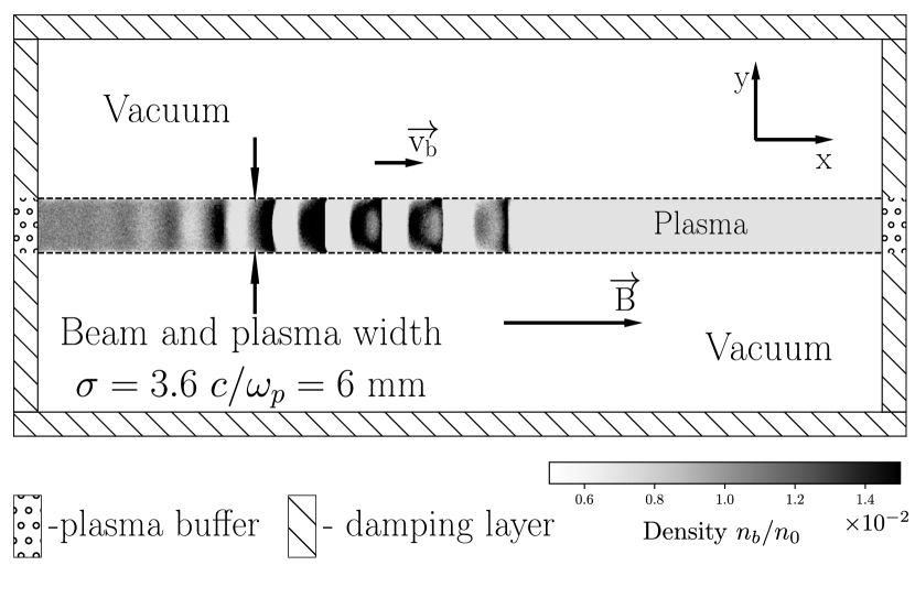
Damping layers for EM radiation are placed near all borders of the simulation box. A plasma column is located in the middle of the system and separated in the transverse direction from the boundaries by vacuum layers. In the longitudinal direction, plasma is limited by plasma buffers in which the particle distribution similar to the ones inside the boundary plasma cells is maintained. New beam particles are created in these plasma buffers at each time step and then injected into the plasma. If any plasma particle goes beyond the edge of plasma column in the longitudinal direction, it is removed from the simulation. A more detailed description of the open boundary conditions and absorbing layers implemented in this code can be found inAnnenkov et al. (2018b).
In the laboratory experiments at the GOL-3 facility, plasma has been created via gas ionization by an electron beam itself, therefore their transverse sizes coincide with each other. In presented simulations, we set this size equal to , which corresponds to mm for the plasma density cm-3. Vacuum regions have a size cm. The total system length is cm.
Plasma electrons have the Maxwellian momentum distribution with the initial temperature . Plasma ions have the real mass and are initially cold. We use 196 macroparticles in a cell for each particle sort.
The beam density is . For an axially symmetric beam with the diameter mm and energy 100 keV, this density corresponds to the electric current A. Since we are not interested in transient processes associated with a smooth growth of beam current, we inject a beam with a sharp front that creates a seed for the development of the two-stream instability and contributes to a more rapid transition to a nonlinear saturation state.
II.2 Electron beam distribution
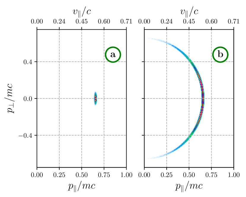
Since the details of the beam momentum distribution significantly affect both the growth rate of unstable oscillations and their level of nonlinear saturation, we will try to reproduce these details in numerical simulations as realistically as possible. In the real experiment, a beam is created by a diode with a plasma emitter in the region with the low external magnetic field ( T). After acceleration to the required energy, the beam electrons remain almost monoenergetic, but acquire an angular distribution with a characteristic scatter Burdakov et al. (2013); Astrelin et al. (2016). Further transportation of the beam to the region of a strong magnetic field leads to compression of its transverse size in hundreds of times and is accompanied by a significant increase in the angular spread.
In our simulations, such a beam distribution is created in the following way:
-
1.
the momentum of each particle is set in accordance with the shifted Maxwell distribution with the temperature eV and directed momentum corresponding to the energy of 100 keV ();
-
2.
then this momentum is distributed between the longitudinal and transverse components based on the distribution , where is the initial angle spread (, ) (fig. 2 a);
-
3.
transporting a beam from a weak ( T) to a strong magnetic field implies the conservation of the magnetic moment and energy of the particles, therefore the final values of their transverse and longitudinal momenta are defined as , (fig. 2 b) (in the case of particle reflection, , its momentum is calculated anew in order to save the specified beam current value);
-
4.
in the Cartesian coordinates we use, the particle momentum vector is represented as three components: , and , where is a random number from the uniform distribution from to .
III Injection into a homogeneous plasma
We have recently shown Timofeev, Annenkov, and Arzhannikov (2015); Annenkov, Volchok, and Timofeev (2016); Timofeev, Volchok, and Annenkov (2016) that the high efficiency of EM radiation generation in a thin beam-plasma system is possible in the presence of a longitudinal modulation of the plasma density allowing the system to radiate like a dipole antenna. The principal points of this theory are given below.
III.1 The mechanism of a beam-plasma antenna
Let us consider a plane plasma layer with the thickness and density . An electron beam propagating along the axis drives longitudinal plasma waves with the frequency and the wavenumber . Scattering of these oscillations on the density perturbation with the wavenumber results in excitation of plasma oscillations . Such oscillations can have superluminal phase velocities and are able to get into the resonance with vacuum EM waves traveling at an angle to the plasma layer. This resonance is possible only if the period of density modulation is not much different from the wavelength of the beam-driven mode
| (1) |
The ratio between and within this range determines uniquely the angle of radiation
| (2) |
In the particular case , EM radiation escapes from the plasma in the strictly transverse direction. Since the frequency of the dominant mode in the hydrodynamic regime of the two-stream instability is less than the plasma frequency,
| (3) |
the generated radiation is able to efficiently interact with plasma currents only at the skin depth ( is the relativistic factor of the electrons beam). The radiation power near the plasma frequency is proportional to the square of the plasma oscillations amplitude Annenkov, Timofeev, and Volchok (2016a): . We will determine this amplitude from simulation fields as
Besides the fundamental radiation near the plasma frequency, such a system can efficiently produce the second harmonic emission through the nonlinear interaction of the dominant beam-driven mode with its long-wavelength satellite arising due to scattering on the periodic modulation of ion density:
| (4) |
Resulting oscillations of electric current can be a source of EM emission only in the limited range of values (). Thus, for the modulation period corresponding to the range
| (5) |
the main part of EM power should be radiated near the second harmonic of the plasma frequency. The radiation angle is determined by the following expression
| (6) |
In this case, the radiation power is proportional to the fourth power of the amplitude of plasma oscillations Annenkov et al. (2018a): . Despite of the nonlinear character of this process, the power of -radiation can be comparable to the power of linear conversion because of a small difference between the pump and plasma frequency ().
III.2 Simulation results
Let us carry out simulations of continuous electron beam injection into a magnetized plasma for two values of the external magnetic field: T () and T (), where is the electron cyclotron frequency. The former corresponds to the conditions of GOL-3 experimentsBurdakov et al. (2013), while the latter – to the case when the upper hybrid frequency equals to the doubled electron cyclotron frequency . Further, we will conventionally call these fields weak and strong ones.
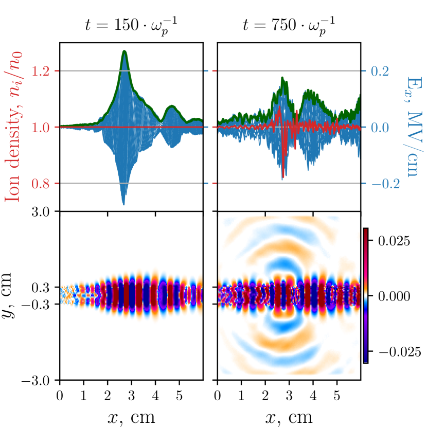
First, consider the evolution of plasma oscillations at the early stages of the beam-plasma instability. For both values of the external magnetic field, the most intense beam-plasma interaction is localized at a distance of less than cm from the injector. The linear stage of the two-stream instability is followed by the nonlinear process of beam trapping by the field of an excited wave. As a result, spatially localized wave packets with a large amplitude of the longitudinal electric field are formed (Fig. 3 ).
In the strong magnetic field, the role of the most unstable modes are played by oblique oscillations of the upper-hybrid branch getting in the Cherenkov resonance with the beam and having the frequency (Fig. 4 top). These oscillations are excited in the first 3 cm of the plasma. After interacting with them, the beam receives a significant spread in momenta and begins to build up purely longitudinal waves with the frequency . It is slightly lower than the value of that is predicted by the linear theory (3) for a monoenergetic beam. As the plasma electrons are heated, the oblique instability decays and the beam begins to build up longitudinal oscillations in the entire region.
In the weak magnetic field , the beam excites only longitudinal plasma oscillations at the frequency from the very beginning. Since the angular spread of the beam in this case turns out to be noticeably smaller, the instability growth rate increases significantly, shifting the region of intense beam relaxation to the immediate vicinity of the injector (Fig. 4 bottom).
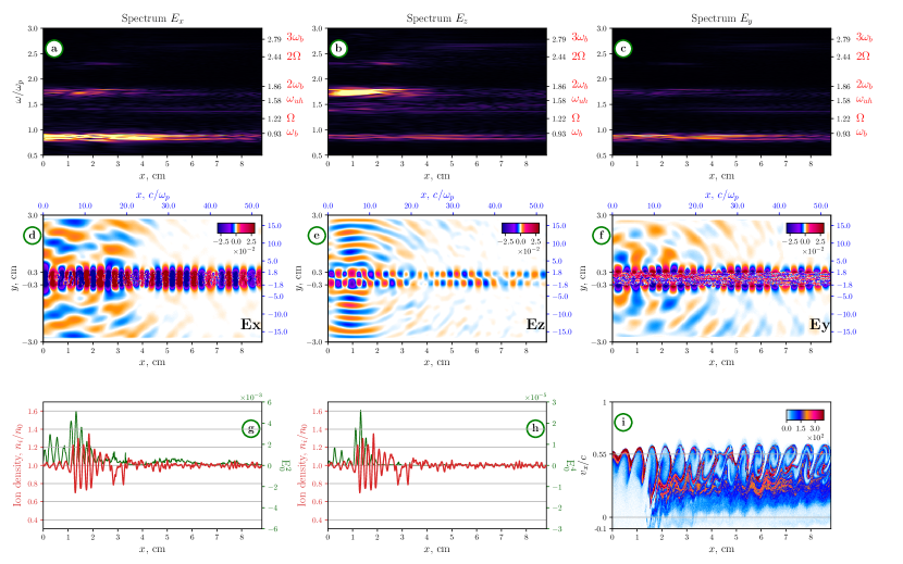
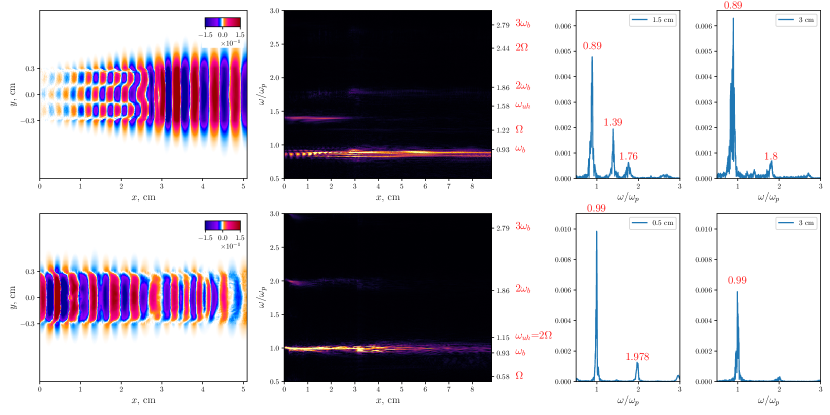
In further, the ponderomotive force of the spatially localized wave packet forms a well on the longitudinal profile of the ion density. The linear mode conversion of plasma waves on this perturbation gives rise to first microbursts of EM radiation near the plasma frequency (Fig. 3 ). At the same time, both in the density profile and in the amplitude of plasma oscillations, we observe a growth of the smaller-scale modulation instability with . The nonlinear stage of this instability ends with the formation of a deep longitudinal modulation of the ion density and transformation of traveling plasma oscillations into a standing wave whose antinodes are localized inside the plasma density wells (Fig. 5 g-h). While oscillations in neighboring wells occur in antiphase (i.e. the standing wave consists of traveling waves with ), they are pumped resonantly by the beam. According to the plasma antenna mechanism, the nonlinear interaction of modes with leads to transverse emission at (Fig. 5 e), and their linear conversion on perturbations with is responsible for radiation at (Fig. 5 d). As neighboring oscillators dephase, they fall out of resonance with the beam and the locked plasma oscillations begin to decay. Thus, the modulational instability of the most unstable beam-driven wave with subsequent trapping of oscillations in density wells and the local disruption of the instability forms a single burst of EM radiation. Maps of the electric fields in the moment of the most intense generation of EM waves in the strong magnetic field are presented in Fig. 5 d-f, while the temporal evolution of a single burst is shown in Fig. 6 a.
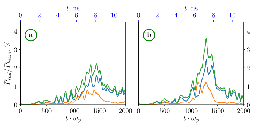
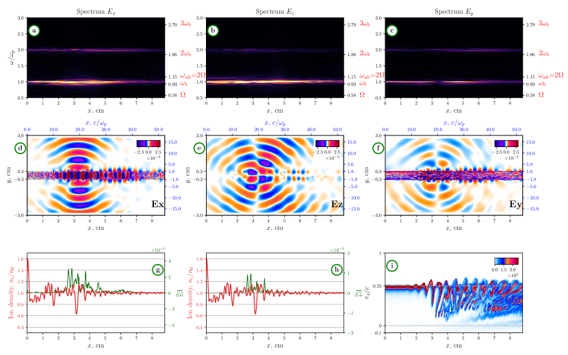
Figure 5 (d,e,g,h) also shows that the fundamental EM emission is less localized than the second harmonic one, which is consistent with our theoretical scalings and . An interesting feature of the considered regime of beam-plasma interaction is that emissions at different harmonics (Fig. 5 a-c) differ in polarizations: the spectrum of the TM mode is dominated by the beam frequency , while in the TE mode, most of the radiation energy is concentrated at the second harmonic. The radiation spectrum also demonstrates the less intensive lines near and indicating that resonant upper hybrid oscillations and harmonic cyclotron emissions are able to escape from the plasma.
Note that the formation of a nonuniform ion density profile depends on a complicated history of the development of the two-stream and modulational instabilities and, for each random realization of the particle distribution function, takes place in its own unique way. In this situation, only the global scenario of the process, the spectrum of the observed radiation, as well as the conclusion about its high generation efficiency remain unchanged. Figure 6 presents the efficiency of the beam-to-radiation power conversion in the case of the strong magnetic field for two simulations differing only in the specific implementation of the initial momentum distribution function of plasma particles. It can be seen that the total radiation power constitutes 2% - 3.5% of the injected beam power, while the efficiency of the -radiation polarized across the magnetic field reaches 1%.
Results of simulations for the weak magnetic field in the moment of the most efficient EM emission are shown in Fig. 7. The corresponding temporal dependence of the relative radiation power is still a set of bursts (Fig. 8 b).
Initially, the most intense beam-plasma interaction was localized in the immediate vicinity of the injector. This contributed to the formation of a small-scale ion density modulation there. As can be seen from Fig. 7 d and g, this modulation led to a complete disruption of the instability in this region. As a result, the beam began to pump oscillations effectively in a more remote area (3-4 cm) which eventually also became a source of EM emission.
Let us analyze the role of the antenna mechanism in the generation of such radiation. For this purpose, we consider the spectra of ion density (fig. 9 a) and plasma oscillations (fig. 9 d) in the same moment of time that is shown in Fig. 7. In addition, we present the emission spectrum (Fig. 9 c) in a single spatial point near the absorbing layer lying oppositely the radiating region and also indicate areas in the ()-space (Fig. 9 b) in which the conditions (1) and (5) for antenna emissions are satisfied ().
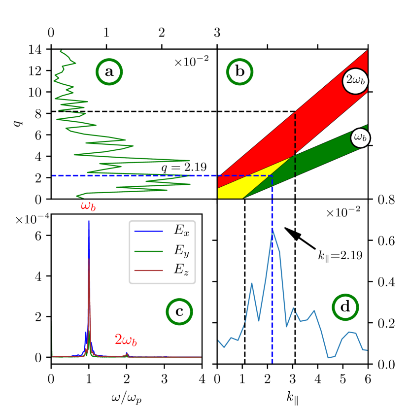
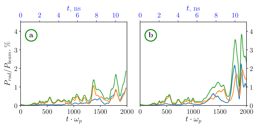
In the spectrum of plasma oscillations, it is observed the dominance of the beam mode with the wavenumber that is coincides with one of the main peaks of the ion density spectrum . This situation corresponds to the transverse antenna emission near the plasma frequency. For the remaining spectral lines, it is also possible to generate EM waves at an angle to the plasma layer at both harmonics, which is confirmed by the electric field map and the emission spectrum shown in Fig. 7. In contrast to the case of the strong magnetic field , the fundamental EM emission here dominates in all polarizations. Figure 8 shows the hystory of radiation efficiency for two different simulations with the magnetic field . For each polarization, the radiation power also reaches 1%-2% of the beam power.
IV Disruption of the beam-plasma instability
Presented simulations show the possibility of generating EM waves by an electron beam in an initially uniform plasma channel with the high efficiency of power conversion (a few %). But compact radiating regions turn out to be located at a distance of several centimeters from the injector, which cannot explain experimental observations of efficient -emission at a distance of 84 cm. As it has been already discussed for the case , small-scale ion density perturbations growing due to the modulational instability enable to completely disrupt the two-stream instability. As a result, the beam becomes capable of pumping plasma waves in regions more distant from the injector. It is logically to assume that, in the future, a highly inhomogeneous density profile will be formed also in these new regions forcing the beam to relax further and further away from the injector. Such a scenario could explain the wider region of intense beam-plasma interaction observed in laboratory experiments on microsecond time-scales.
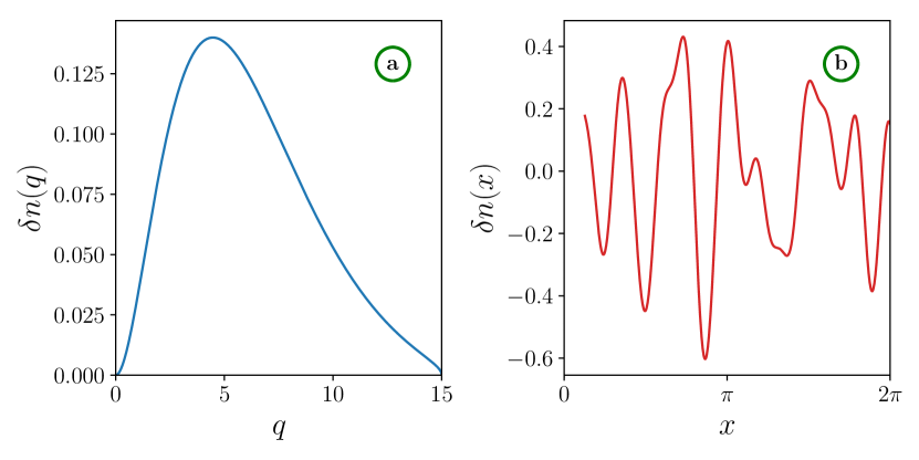
To verify this hypothesis, we carry out simulations with a preformed turbulent ion density profile. The following function is taken as a model spectrum of density fluctuations (Fig. 10 a):
| (7) |
where is the wavenumber of the longitudinal density modulation, and are distribution parameters, ia a maximal considered harmonic.
From this distribution, uniformly arranged harmonics are selected. For each of them, we calculate the resulting amplitude and random phase in the range :
| (8) | ||||
| (9) |
where is a maximum value of the distribution function and . The final plasma density is created in the form (Fig. 10 b):
| (10) |
Figure 11a shows the phase plane of the beam in the case of its injection into a homogeneous plasma with fixed ions in the magnetic field . The beam-plasma instability is seen to be developed in the immediate vicinity of the injection area and, at a distance of 5 cm, beam-driven plasma oscillations reach amplitudes capable of stopping beam particles.
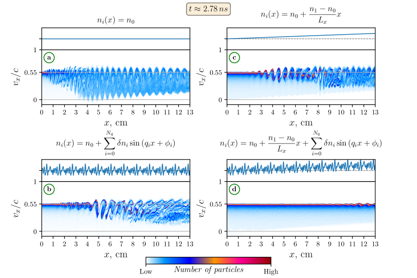
In the case of turbulent density (Fig. 11 b), we observe that the beam-plasma instability is significantly weakened in the first centimeters of plasma, but oscillations still reach the nonlinear level of beam trapping further from the injector. Thus, the presence of small-scale density perturbations in a plasma with a sufficiently wide spectrum results in only weakening the instability, but not in its complete disruption.
Another possible explanation for the ability of the beam to generate EM radiation far from the injector is the presence of a large-scale longitudinal density gradient caused by the nonuniform gas inlet into the vacuum chamber. To test this idea, we simulate the beam injection into a plasma with the density:
where cm-3, cm-3 and cm. The result is shown in Figure 11 c. The presence of such a gradient also weakens the beam-plasma instability, but does not lead to its complete disruption.
The presence of intense oscillations in a plasma with a longitudinal density gradient will eventually lead to the development of modulation instability and the formation of a turbulent density spectrum. So it is to study the influence of a large-scale gradient with small-scale turbulence on the beam relaxation:
The result of simulation with such a plasma density is shown in Fig. 11 d. It is seen that such an inhomogeneity is able to disrupt the instability on a scale of 10 cm.
V Scenario of experiment
According to the simulation results, relaxation of an electron beam with an energy of 100 keV and a current of 75 A in the conditions of the laboratory experiment at the GOL-3 facility Burdakov et al. (2013) should proceed according to the following scenario. The beam ionizes the gas in its cross section and, due to the development of the two-stream instability, excites longitudinal oscillations in the resulting plasma channel. Since the gas density at the first meter of the trap varies by a factor of 10, the growth rate of this instability turns out to be lower than in a homogeneous plasma. Therefore, plasma oscillations excited by the beam reach their nonlinear saturation at a distance of 10 cm. Due to the development of the modulational instability of the dominant beam-driven wave with , small-scale periodic perturbations of ion density with the wavenumbers begin to grow. Due to the small transverse size of the system, comparable to the radiation wavelength, the linear and nonlinear conversion of the beam wave on these perturbations via the antenna mechanism leads to the emission of EM waves at the plasma frequency and its second harmonic. The region of intense beam-plasma interaction has a size of 1-3 cm, and the radiation from it has the bursty character. The duration of bursts is determined by the growth time of the modulational instability and takes 1-5 ns in our simulations. The repetition period of such bursts should be determined by the longer time of the ion density relaxation that recreates favorable conditions for the new buildup cycle of the beam-plasma instability. The peak radiation power in a single burst can be several percent of the beam power, and in a strong magnetic field , a significant part of this power is contained in the transversely polarized -radiation. After a local disruption of the beam-plasma instability, the region of intense beam relaxation shifts away from the injector. Based on the performed simulations, it can be assumed that, for the beam current under study, the formation of small-scale perturbations on a large-scale density gradient leads to a shift of intense beam-plasma interaction to the region of 10-20 cm.
It should be noted that the considered regime with a current of 75 A does not allow direct comparison with the experiment in which, at a given current, no EM radiation has been detected Burdakov et al. (2013) at the location of radiometric diagnostics (84 cm from the injector). Highly efficient EM emission in this place has been observed only in a narrow range of weaker currents of 20-30 A. Since simulations of weak currents on a scale of 1 m goes beyond the computing resources available to us, we restrict ourselves to a qualitative assessment of the adequacy of the scenario that is observed in the regime already studied.
First, our simulations allow to answer the question of why radiation has not been registered at the location of 84 cm with beam currents above 75 A. Intense radiation at the harmonics of the plasma frequency in this case should be generated in the region of 10–20 cm. The decrease of the beam current and its relative density reduces the growth rate of the beam-plasma instability and increases the stabilizing effect of density inhomogeneities shifting the region of efficient beam-plasma interaction further from the injector. It is likely that, for A, this region comes to the visibility zone of the radiation detection system.
Second, our simulation studies confirm the principle possibility to generate radiation at the doubled plasma frequency with the efficiency of 1% that is unusually high for a turbulent beam-plasma system. The beam-driven plasma antenna is proposed for the role of the mechanism capable of providing such an efficient EM emission.
Third, the established scenario makes it possible to interpret the bursty nature of radiation in experiments as a cyclic process in which the buildup of the two-stream instability in a very compact region of 1-3 cm is accompanied by the growth of longitudinal modulation of the ion density followed by getting out of resonance of trapped oscillations with the beam and subsequent relaxation of small-scale density inhomogeneities. Taking into account the longer period of such a cycle at low currents, this process may be responsible for the generation of individual bursts with the typical duration of 20 ns observed in experiments Postupaev2013 .
VI Summary
We have carried out PIC simulations of continuous injection of a thin sub-relativistic electron beam into a magnetized plasma channel with the parameters of a laboratory experiment at the GOL-3 mirror trap and have shown the principal possibility of generating EM radiation near the plasma frequency and its second harmonic with a total power of several percent of beam power. We have found regimes when a significant fraction of this power falls on the second harmonic, which is consistent with the estimates of the efficiency of such radiation in the experiment. The conducted studies shed light on the physics of beam relaxation in these experiments and allow a qualitative interpretation of their results. In particular, it has become clear that, even in a strong magnetic field, the radiation is tied to the plasma frequency harmonics, but not to the upper hybrid resonance or cyclotron frequencies. We have also confirmed that the plasma antenna mechanism can work efficiently under the experimental conditions, have described a scenario for the formation of individual radiation bursts and explained why radiations produced in the high-current regimes (75 A) cannot be detected by existing diagnostics.
Note that the same regime of a thin beam can be realized in a denser plasma with a beam of millimeter diameter and kiloampere currents, which opens the prospect of equally effective generation of high-power radiation in the THz frequency range.
This work was supported by RFBR (Grant No.18-02-00232).
References
- Gurnett and Anderson (1976) D. A. Gurnett and R. R. Anderson, Science 194, 1159 (1976).
- Goldman, Reiter, and Nicholson (1980) M. V. Goldman, G. F. Reiter, and D. R. Nicholson, Physics of Fluids 23, 388 (1980).
- Whelan and Stenzel (1985) D. A. Whelan and R. L. Stenzel, Physics of Fluids 28, 958 (1985).
- (4) P.L. Pritchett and J.M. Dawson, Phys. Fluids 26, 1114 (1983).
- Benford et al. (1980) G. Benford, D. Tzach, K. Kato, and D. F. Smith, Physical Review Letters 45, 1182 (1980).
- Whelan and Stenzel (1981) D. A. Whelan and R. L. Stenzel, Physical Review Letters 47, 95 (1981).
- Cheung et al. (1982) P. Y. Cheung, A. Y. Wong, C. B. Darrow, and S. J. Qian, Physical Review Letters 48, 1348 (1982).
- Che et al. (2017) H. Che, M. L. Goldstein, P. H. Diamond, and R. Z. Sagdeev, Proceedings of the National Academy of Sciences of the United States of America 114, 1502 (2017).
- Li and Cairns (2013) B. Li and I. H. Cairns, Journal of Geophysical Research: Space Physics 118, 4748 (2013).
- Robinson and Cairns (1998) P. A. Robinson and I. H. Cairns, Solar Physics 181, 363 (1998).
- Thejappa and MacDowall (1998) G. Thejappa and R. J. MacDowall, Apj 498, 465 (1998).
- Thurgood and Tsiklauri (2015) J. O. Thurgood and D. Tsiklauri, Astronomy & Astrophysics 584, A83 (2015).
- Chernov (2010) G. P. Chernov, Research in Astronomy and Astrophysics 10, 821 (2010).
- Kuznetsov and Vlasov (2013) A. Kuznetsov and V. Vlasov, Planetary and Space Science 75, 167 (2013).
- Postupaev et al. (2011) V. Postupaev, A. V. Arzhannikov, V. Astrelin, V. Batkin, A. V. Burdakov, V. S. Burmasov, I. Ivanov, M. Ivantsivsky, K. Kuklin, S. Kuznetsov, M. Makarov, K. Mekler, S. Polosatkin, S. Popov, A. Rovenskikh, A. Shoshin, S. Sinitsky, V. Sklyarov, N. Sorokina, A. Sudnikov, Y. Sulyaev, and L. Vyacheslavov, Fusion Science and Technology 59, 144 (2011).
- Arzhannikov and Timofeev (2012) A. V. Arzhannikov and I. V. Timofeev, Plasma Physics and Controlled Fusion 54, 105004 (2012).
- Arzhannikov et al. (2014) A. V. Arzhannikov, A. V. Burdakov, V. S. Burmasov, D. E. Gavrilenko, I. A. Ivanov, A. A. Kasatov, S. A. Kuznetsov, K. I. Mekler, S. V. Polosatkin, V. V. Postupaev, A. F. Rovenskikh, S. L. Sinitsky, V. F. Sklyarov, and L. N. Vyacheslavov, Physics of Plasmas 21, 082106 (2014).
- (18) A.V. Arzhannikov, A.V. Burdakov, V.S. Burmasov, I.A. Ivanov, A.A. Kasatov, S.A. Kuznetsov, M.A. Makarov, K.I. Mekler, S.V. Polosatkin, S.S. Popov, V.V. Postupaev, A.F. Rovenskikh, S.L. Sinitsky, V.F. Sklyarov, V.D. Stepanov, I.V. Timofeev, and M.K.A. Thumm, IEEE Trans. Terahertz Sci. Technol. 6, 245 (2016).
- Burdakov et al. (2013) A. V. Burdakov, A. V. Arzhannikov, V. S. Burmasov, I. A. Ivanov, M. V. Ivantsivsky, I. V. Kandaurov, S. A. Kuznetsov, V. V. Kurkuchekov, K. I. Mekler, S. V. Polosatkin, S. S. Popov, V. V. Postupaev, A. F. Rovenskikh, V. F. Sklyarov, M. K. A. Thumm, Y. A. Trunev, and L. N. Vyacheslavov, Fusion Science and Technology 63, 286 (2013).
- (20) V.V. Postupaev, A.V. Burdakov, I.A. Ivanov, V.F. Sklyarov, A.V. Arzhannikov, D.Y. Gavrilenko, I.V. Kandaurov, A.A. Kasatov, V.V. Kurkuchekov, K.I. Mekler, S.V. Polosatkin, S.S. Popov, A.F. Rovenskikh, A.V. Sudnikov, Y.S. Sulyaev, Y.A. Trunev, and L.N. Vyacheslavov, Phys. Plasmas 20, 092304 (2013).
- Ivanov et al. (2015) I. A. Ivanov, A. V. Arzhannikov, A. V. Burdakov, V. S. Burmasov, D. E. Gavrilenko, A. A. Kasatov, I. V. Kandaurov, V. V. Kurkuchekov, S. A. Kuznetsov, K. I. Mekler, S. V. Polosatkin, S. S. Popov, V. V. Postupaev, A. F. Rovenskikh, V. F. Sklyarov, N. V. Sorokina, Y. A. Trunev, and L. N. Vyacheslavov, Physics of Plasmas 22, 122302 (2015).
- Timofeev, Annenkov, and Arzhannikov (2015) I. V. Timofeev, V. V. Annenkov, and A. V. Arzhannikov, Physics of Plasmas 22, 113109 (2015).
- Annenkov, Volchok, and Timofeev (2016) V. V. Annenkov, E. P. Volchok, and I. V. Timofeev, Plasma Physics and Controlled Fusion 58, 045009 (2016).
- Timofeev, Volchok, and Annenkov (2016) I. V. Timofeev, E. P. Volchok, and V. V. Annenkov, Physics of Plasmas 23, 083119 (2016).
- Annenkov, Timofeev, and Volchok (2016a) V. V. Annenkov, I. V. Timofeev, and E. P. Volchok, Physics of Plasmas 23, 053101 (2016a).
- Annenkov et al. (2018a) V. V. Annenkov, E. A. Berendeev, E. P. Volchok, and I. V. Timofeev, (2018a), arXiv:1811.06426 .
- Annenkov, Timofeev, and Volchok (2016b) V. V. Annenkov, I. V. Timofeev, and E. P. Volchok, in AIP Conference Proceedings, Vol. 1771 (AIP Publishing LLCAIP Publishing, 2016) p. 070011.
- Ryutov (1969) D. Ryutov, Soviet Journal of Experimental and Theoretical Physics 30, 131 (1969).
- Nishikawa and Ryutov (1976) K. Nishikawa and D. D. Ryutov, Journal of the Physical Society of Japan 41, 1757 (1976).
- Krafft et al. (2014) C. Krafft, A. S. Volokitin, V. V. Krasnoselskikh, and T. D. de Wit, Journal of Geophysical Research: Space Physics 119, 9369 (2014).
- Pechhacker and Tsiklauri (2014) R. Pechhacker and D. Tsiklauri, Physics of Plasmas 21, 012903 (2014), arXiv:1401.6966 .
- Thurgood and Tsiklauri (2016) J. O. Thurgood and D. Tsiklauri, Journal of Plasma Physics 82, 905820604 (2016), arXiv:1612.01780 .
- Schmitz and Tsiklauri (2013) H. Schmitz and D. Tsiklauri, Physics of Plasmas 20, 062903 (2013).
- Pechhacker and Tsiklauri (2012) R. Pechhacker and D. Tsiklauri, Physics of Plasmas 19, 112903 (2012), arXiv:1211.6726 .
- Sheng, Mima, and Zhang (2005) Z. M. Sheng, K. Mima, and J. Zhang, Physics of Plasmas 12, 1 (2005).
- Petrenko, Lotov, and Sosedkin (2016) A. Petrenko, K. Lotov, and A. Sosedkin, Nuclear Instruments and Methods in Physics Research Section A: Accelerators, Spectrometers, Detectors and Associated Equipment 829, 63 (2016).
- Faure et al. (2010) J. Faure, C. Rechatin, O. Lundh, L. Ammoura, and V. Malka, Physics of Plasmas 17, 083107 (2010).
- Lindholm et al. (2008) E. Lindholm, J. Nickolls, S. Oberman, and J. Montrym, in IEEE Micro, Vol. 28 (2008) pp. 39–55.
- Yee (1966) K. S. Yee, “Numerical Solution of Initial Boundary Value Problems Involving Maxwell’s Equations in Isotropic Media,” (1966).
- Boris (1970) J. P. Boris, Proceeding of Fourth Conference on Numerical Simulations of Plasmas (1970).
- Esirkepov (2001) T. Esirkepov, Computer Physics Communications 135, 144 (2001).
- Annenkov et al. (2018b) V. V. Annenkov, E. A. Berendeev, I. V. Timofeev, and E. P. Volchok, Physics of Plasmas 25, 113110 (2018b).
- Astrelin et al. (2016) V. T. Astrelin, I. V. Kandaurov, V. V. Kurkuchekov, and Y. A. Trunev, in AIP Conference Proceedings, Vol. 1771 (AIP Publishing LLC, 2016) p. 030019.