Direct calculation of the strong Goos-Hänchen effect of a Gaussian light beam due to the excitation of surface plasmon polaritons in the Otto configuration
Abstract
We study theoretically the influence of the surface plasmon excitation on the Goos-Hänchen lateral shift of a -polarized Gaussian beam incident obliquely on a dielectric-metal bilayer in the Otto configuration. We find that the lateral shift depends sensitively on the thickness of the metal layer and the width of the incident beam, as well as on the incident angle. Near the incident angle at which surface plasmons are excited, the lateral shift changes from large negative values to large positive values as the thickness of the metal layer increases through a critical value. For wide incident beams, the maximal forward and backward lateral shifts can be as large as several hundred times of the wavelength. As the width of the incident Gaussian beam decreases, the magnitude of the lateral shift decreases rapidly, but the ratio of the width of the reflected beam to that of the incident beam, which measures the degree of the deformation of the reflected beam profile, increases. In all cases considered, we find that the reflected beam is split into two parts. We also find that the lateral shift of the transmitted beam is always positive and very weak.
1 Introduction
A light beam deviates from the path expected from geometrical optics when it is totally reflected at the interface between two different media. The reflected beam is displaced laterally along the interface, which is called the Goos-Hänchen (GH) shift. This phenomenon has been predicted a long time ago and measured experimentally by Goos and Hänchen for the first time [1, 2, 3]. Artmann has derived an analytical formula for the GH shift for incident plane waves [4]. The GH effect occurs in many diverse areas such as acoustics, optics, plasma physics and condensed matter physics [5, 6].
Earlier works have treated the GH shift in multilayered structures in the Otto or Kretschmann configuration [7, 8, 9]. Tamir and Bertoni performed a detailed analysis of the electromagnetic field distribution in a leaky-wave structure upon which a Gaussian beam is incident [10]. It has been demonstrated that the reflected beam displays either a forward or a backward beam shift. An approximate analytical solution has shown that the initial Gaussian beam profile splits into two. The theory of leaky waves has also been applied to acoustic beams incident on a liquid-solid interface, with the aim of presenting a unified theory of the beam shifting effect near the Rayleigh angle [11].
The GH effect of a light beam incident on a dielectric slab from the air has been studied with an emphasis on the transmitted beam [12]. Lakhtakia has pointed out that the GH shift reverses its direction when and in the optically rarer medium [13]. The enhancement of the GH shift and the control of the reflected field profile has been achieved by adding a defect or cladding layer to photonic crystals [14, 15]. Recently, De Leo et al. have performed an extended study investigating the asymmetric GH effect and derived an expression for the GH shift valid in the region where the Artmann formula diverges [16, 17, 18, 19].
Light waves confined to the surface of a medium and surface charges oscillating resonantly with the light waves constitute the surface plasmon polaritons (SPPs). The enhancement of electromagnetic fields near the surface caused by the excitation of SPPs has generated practical applications in sensor technology [20, 21, 22]. These applications include thin film probing [23], biosensing [24] and biological imaging [25]. In the Otto or Kretschmann configuration, the SPPs are excited by attenuated total internal reflection by enhancing the momentum of the incident light [26, 27].
The excitation of SPPs in the Otto or Kretschmann configuration affects the GH shift profoundly. Early results on the influence of SPPs on the shift of light beams can be found in [28] and [29]. It has been shown that the interaction of leaky waves with SPPs enhances the GH shift. Results on the excitation of surface waves in the Otto configuration have been reported by Chen et al. [30]. Chuang has conducted an analysis of the behavior of the reflection coefficient for both Otto and Kretschmann configurations [31]. The zeros and poles of the reflection coefficient move around the complex plane with the change of parameters, such as the beam width, the wavelength, the thickness and the dielectric constants. Zeller et al. have shown that the coupling of an incident wave with the SPP is highly dependent on the thickness of the dielectric sublayer in both the Kretschmann and Otto configuration [32, 33, 34]. Shadrivov et al. have studied the GH shift in the Otto configuration with the metal sublayer substituted by a left-handed metamaterial [35]. A large GH shift with beam splitting was observed, and the energy transfer between the right- and left-handed materials was demonstrated by numerical simulations. There also exist studies to enhance the GH shift using various hybrid structures containing sublayers of graphene, MoS2 or cytop [36, 37, 38]. Recently, much progress has been made on obtaining a tunable GH shift in the prism-coupling system, by applying an external voltage to a graphene sublayer and other heterostructures [39, 40, 41, 42]. Kim et al. have studied the GH shift of incident waves in the Otto configuration containing a nonlinear dielectric layer and shown that its magnitude can be as large as several hundred times of the wavelength at the incident angles where the SPPs are excited [43]. Furthermore, they have shown that the sign and the size of the GH shift can change very sensitively as the nonlinearity parameter varies.
In this paper, we study the strong enhancement of the GH effect for incident Gaussian beams when SPPs are excited at the metal-dielectric interface in the Otto configuration. We examine the influence of varying the thickness of the metal layer and the incident beam width on the GH effect and find out optimal configurations for maximal forward and backward lateral shifts.
Our theoretical method is based on the invariant imbedding method, using which we transform the wave equation into a set of invariant imbedding equations to create an equivalent initial value problem [44, 45, 46, 47]. For the simplest case of multilayered structures made of uniform linear media, this method is equivalent to those based on the Fresnel coefficients. The invariant imbedding method has been employed to calculate the GH shift for plane waves incident on nonlinear media [43, 48]. It can also be applied to the case of graded media. Here we consider the interaction of a Gaussian beam with linear media. More details of our model and method will be presented in the next section.
2 Generalization of the invariant imbedding method to Gaussian beams
We assume the layered structure lies in . A Gaussian beam with a finite half-width is incident from the region where at an angle . For a -polarized beam propagating in the plane, the component of the magnetic field associated with the incident beam at the plane can be written as
| (1) |
where is the half-width in the direction. The center of the incident beam is at . The parameter () is the component of the wave vector corresponding to the incident angle and is the wave number in the incident region, which corresponds to the prism. The superscript refers to the incident beam.
We consider the incident Gaussian beam as a linear combination of plane waves and write its field as
| (2) |
where the Fourier transform is given by
| (3) |
The variable can be parameterized as . We write the reflection and transmission coefficients corresponding to each Fourier component as and respectively. Then the field profiles for the reflected and transmitted beams and are given by
| (4) |
where () and are the negative components of the wave vector in the incident () and transmitted () regions respectively.
The GH shifts for the reflected and transmitted beams, which are also known as the normalized first momenta of the magnetic field [35], are defined by
| (5) |
The reflected and transmitted beams will be severely deformed when the half-width of the incident beam is small. In order to measure the degree of the deformation of the reflected and transmitted beams, we calculate the normalized second momenta of the magnetic field defined by
| (6) |
These expressions are just the first and second moments of a distribution function and give the average and the variance for a given statistical distribution function. The first moment can also be interpreted as the centroid of the area under the distribution curve. The half-widths of the reflected and transmitted beams, and , are obtained using
| (7) |
In the expressions given above, the reflection and transmission coefficients play a crucial role. In order to calculate and in the wave vector space, we resort to the invariant imbedding method, which we summarize here briefly. For a -polarized wave propagating in a nonmagnetic () layered structure along the plane, the complex amplitude of the magnetic field, , satisfies the wave equation
| (8) |
where () is the vacuum wave number and is the dielectric permittivity. We consider a plane wave of unit magnitude incident on the medium lying in from the region where at an angle . The complex reflection and transmission coefficients and , which we consider as functions of , are defined by the wave functions outside the medium by
| (9) |
When is equal to in and in , the wave vector components , and are given by , and , where is the angle that outgoing waves make with the negative axis.
We can transform the wave equation into a set of differential equations for the reflection and transmission coefficients using the invariant imbedding method [44]:
| (10) |
These equations are integrated from to using the initial conditions given by the Fresnel formulas
| (11) |
The reflection and transmission coefficients and calculated above are employed into the integral in (4), multiplying each Fourier component.
The GH shift for reflected plane waves is computed and compared with those of beams, using Artmann’s formula
| (12) |
where is the wavelength and is the phase of the reflection coefficient satisfying .
3 Numerical results and discussion
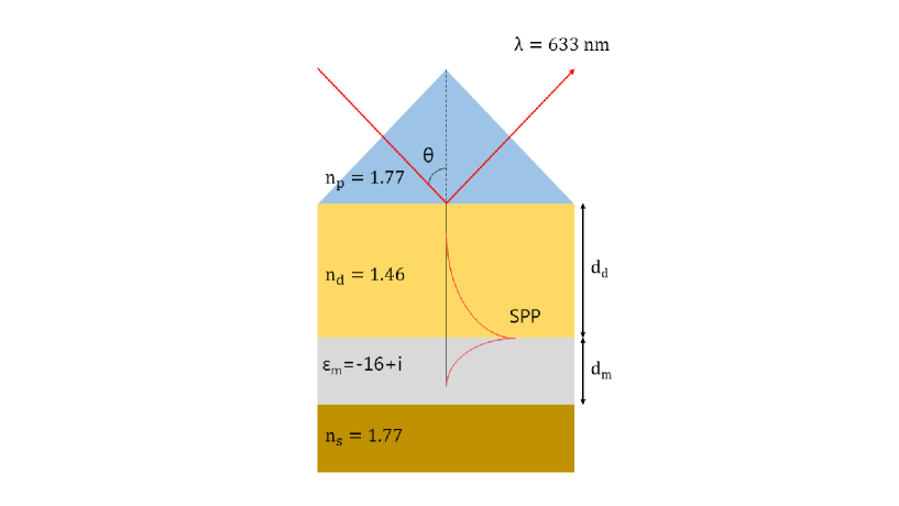
We assume that a -polarized beam is incident from a prism onto a dielectric-metal bilayer, which lies on a dielectric substrate, at room temperature. Both the prism and the substrate are assumed to have the same refractive index of 1.77 corresponding to sapphire. The refractive index of the dielectric layer is 1.46 corresponding to fused silica (). Then the critical incident angle is equal to . The vacuum wavelength of the incident wave is 633 nm and the dielectric permittivity of the metal layer is corresponding to silver at nm. In figure 1, we show the schematic of our configuration. We note that we have a propagating wave in the substrate in the present geometry.

We first consider the case where plane waves are incident. In figure 2, we plot the GH shift normalized by the wavelength, , of the reflected wave calculated from Artmann’s formula for plane waves versus the thickness of the metal layer normalized by the wavelength, , when is fixed to . As is increased through the critical value , changes rapidly from large negative values to large positive values. The value of the largest backward normalized GH shift is about at , while that of the largest forward normalized GH shift is about 4214 at . We note that the change of from to corresponds to the thickness change of just 0.076 nm. From many numerical calculations, we have found that the maximum GH shifts are obtained when . Since the values of the GH shift for plane waves are much larger than those obtained for Gaussian beams and shown in figure 4(a) below, we show them in separate figures.
Shen et al. have presented the results of the calculation and the measurement of the phase shift of the reflected wave in the Kretschmann configuration as a function of the incident angle [49]. It has been shown that the phase shift decreases monotonically with , which corresponds to the forward GH shift, when the metal (Ag) layer is relatively thin, while it increases monotonically, which corresponds to the backward GH shift, when the metal layer is relatively thick. Shen et al. have shown that the forward shift changes to the backward shift when the metal layer thickness changes by only a few nanometers. We notice that the sign of the GH shift changes from negative to positive as increases in our case of the Otto configuration, whereas it changes from positive to negative in Shen et al.’s case of the Kretschmann configuration.

In figures 3(a) and 3(b), we show the forward GH shift for the reflected plane wave and the corresponding phase of the reflected wave as a function of the incident angle, when . We find that changes very rapidly and the GH shift becomes extremely large near . The maximum is about 7450 at . Similarly, in figures 3(c) and 3(d), we show the backward GH shift for the reflected plane wave and the corresponding phase of the reflected wave obtained for . is about at in this case. We find that the maximal forward and backward GH shifts occur at the same incident angles where the reflectance takes a minimum value.
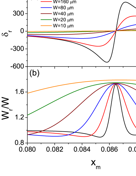
We now consider the case where Gaussian light beams are incident. In figure 4(a), we plot the normalized GH shift of the reflected beam versus , for several different values of the half-width of the incident Gaussian beam. The incident angle is fixed to . For the displayed range of , varies from 50.64 nm to 56.97 nm. The thickness of the dielectric layer, , is chosen such that , therefore is equal to 319.98 nm. The specific values of and were chosen so as to maximize the largest value of the GH shift.
We observe in figure 4(a) that the GH shift of the reflected beam changes its sign from negative to positive as increases through a critical value . This value and the corresponding critical thickness of the metal layer, , are found to vary very little as is decreased from 320 m to 40 m . As is decreased further, decreases noticeably. is about 0.0862 and is about 54.56 nm when is 40 m, while is about 0.0825 and is about 52.22 nm when is 10 m . The maximal forward and backward lateral shifts are close to the half-width of the incident beam. For example, the beam with is shifted by in the forward direction and by in the backward direction. For nm, these correspond to 313.2 m and m respectively. Our numerical results are summarized in Table 1. We notice that for , the forward GH shift has no local maximum.
| (m) | ||||||||
|---|---|---|---|---|---|---|---|---|
| 0.08648 | 0.08654 | 4214.2 | 0.08642 | – | – | |||
| 320 | 505.53 | 0.08647 | 0.08717 | 494.72 | 0.08581 | 0.08647 | 1.72054 | |
| 160 | 252.76 | 0.08646 | 0.08788 | 258.86 | 0.08517 | 0.08647 | 1.72957 | |
| 80 | 126.38 | 0.08640 | 0.08939 | 135.19 | 0.08396 | 0.08647 | 1.73259 | |
| 40 | 63.19 | 0.08617 | 0.09286 | 72.20 | 0.08173 | 0.08648 | 1.73621 | |
| 20 | 31.6 | 0.08530 | 0.10287 | 40.69 | 0.07790 | 0.08652 | 1.74811 | |
| 10 | 15.8 | 0.08246 | – | – | 0.07196 | 0.08683 | 1.78945 |
Our result can be understood from the theory of the GH shift in multilayered structures, where the sign of the GH shift is determined by the competition between intrinsic damping and radiative damping [50, 51]. As the thickness of the dielectric or metal layer is varied, the GH shift becomes positive if the intrinsic damping (absorption loss in the lossy layer) is less than the radiative damping (leakage from the dielectric layer to the prism), and negative otherwise. Our result is consistent with this argument, since the intrinsic damping is inversely proportional to the thickness of the metal layer [51]. Thus the reduction of enhances the intrinsic damping, resulting in the negative GH shift in figure 4(a).
Zeller et al. have also performed a theoretical analysis of the reflection coefficient associated with -polarized SPPs in the Otto configuration containing a layer of a negative-index metamaterial instead of a metal layer [34]. They have found that the sign of the GH shift changes from negative to positive as the thickness of the dielectric layer, , increases.
In figure 4(b), we plot the half-width of the reflected beam normalized by versus . This value takes a maximum at for , 160 and 80 m. The thickness for the maximum increases slightly to for m. Thus the maximum distortion of the beam occurs near the critical thickness of the metal layer, but not at the exactly same thickness. We observe that is larger and the overall curve is broader when the GH shift is smaller and when the incident beam is narrower.
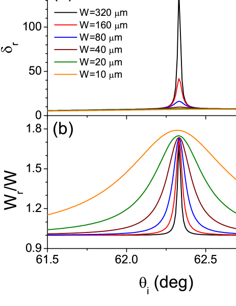
In figure 5(a), we plot as a function of the incident angle for several values of when is 0.5055 and is 0.08657. We find that the maximum value of the forward lateral shift, which is about 140 times of the wavelength when is 320 m and about 42 times of the wavelength when is 160 m, is an order of magnitude smaller than the value in the plane-wave incidence, but is still very large. This value decreases as decreases. Since each Fourier component in the incident beam experiences a different phase shift from each other, the reflected beam, which is the sum of the reflected Fourier components, gets a much smaller GH shift than the case of the plane-wave incidence. As the half-width of the Gaussian beam increases, the magnitude of the lateral shift of the reflected beam increases and approaches the value for the plane-wave incidence. The reflectance for plane waves takes a dip at and the maximum of occurs at the reflectance dip.
In figure 5(b), we show the normalized half-width of the reflected beam, , as a function of the incident angle for each half-width of the incident Gaussian beam. We find that the half-width of the reflected beam at the reflectance dip is substantially larger than that of the incident Gaussian beam. The relative distortion of the reflected beam profile is larger for narrower beams and does not disappear at as the beam width increases.
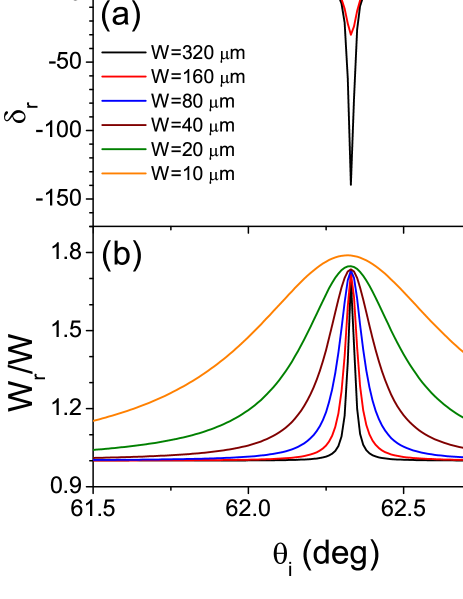
In figure 6(a), we plot as a function of the incident angle for different values of , when is 0.5055 and is 0.08638. We find that the GH shift at the reflectance dip is backward with negative values of when is larger than 40 m in the present case. The maximum value of is about 140 when is 320 m and about 30 when is 160 m. Interestingly, for m, the value of at the reflectance dip becomes positive. The critical thicknesses in figure 4(a) for narrow beams with , 20 and 10 m are , 0.08530 and 0.08246 respectively. Thus in the calculation with presented here, narrow beams have positive GH shifts. In figure 6(b), we show the normalized half-width of the reflected beam as a function of the incident angle for each value of . General characteristics are similar to the forward shift case shown in figure 5(b).
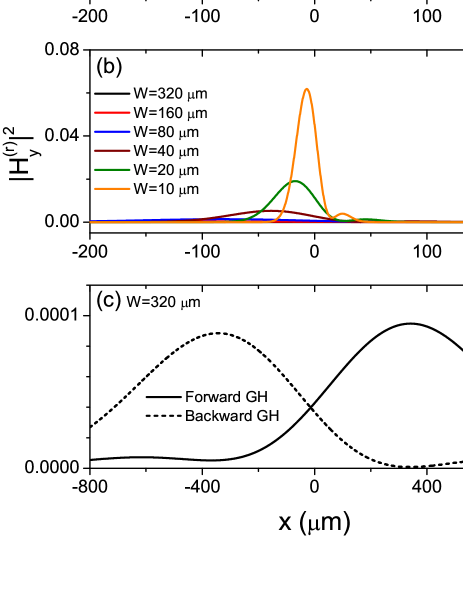
In figures 7(a) and 7(b), we plot the magnetic field intensity distribution associated with the reflected beam at the reflectance dip () for several different values of , when and respectively. In all cases, we observe clearly that the reflected beam is split into two parts. In the case of the plane-wave incidence, the reflectance is very low. This should apply to other Fourier components as well, so the intensity of the reflected beam is substantially weaker than that of the incident beam.
In figure 7(c), we compare the magnetic field profiles associated with the reflected beams corresponding to the backward () and forward () GH shifts, when m and . We observe that the left peak is larger than the right peak in the case of the backward GH shift, while it is vice versa in the case of the positive GH shift. The maximum forward GH shift for the beam with m is about 495 times of the wavelength ( m), which is sufficiently large to be observable in figure 7.
We mention briefly on the GH shift of the transmitted beam, (), as a function of the incident angle for several values of . We find that is positive in all cases and depends very weakly on . The maximum value of is about seven times of the wavelength ( m). For the normalized half-width of the transmitted beam , we find that the value at the reflectance dip is slightly larger than 1. We also find that there is no splitting in the magnetic field intensity distribution of the transmitted beam. The spatial profiles of the transmitted beam look similar to those of the incident Gaussian beam. If we employ a substrate with its refractive index less than 1.5676, we obtain an evanescent transmitted beam. Then there will be another SPP excited at the metal-substrate interface, enhancing the GH shift even further.
There have been several experiments showing both positive and negative GH shifts. In particular, there exist two experiments that have used experimental parameters similar to ours [50, 52]. In [49], the totally reflected -polarized wave is heterodyned with the -polarized wave from the same laser source. In [52], a position-sensitive detector produces a signal that is proportional to the difference of the lateral displacements of - and -polarized waves. Since an wave does not excite SPPs, the obtained signal gives the GH shift of the -polarized wave in both cases. Following similar schemes, it will not be difficult to set up an experiment in the Otto configuration to test our results.
4 Conclusion
In this paper, we have studied the influence of the surface plasmon excitation on the GH effect theoretically, when a Gaussian beam of a finite width is incident on a dielectric-metal bilayer in the Otto configuration. Using the invariant imbedding method, we have calculated the GH lateral shifts of the reflected and transmitted beams and the widths of these beams relative to that of the incident beam. We have found that the lateral shift of the reflected beam depends very sensitively on the thickness of the metal layer and the width of the incident beam. Close to the incident angle at which surface plasmons are excited, the lateral shift of the reflected beam has been found to change from large negative values to large positive values as the thickness of the metal layer increases through a critical value. The maximal forward and backward lateral shifts can be as large as the half-width of the incident beam. As the width of the incident Gaussian beam decreases, we have found that the size of the lateral shift decreases rapidly, but the relative deformation of the reflected beam increases. In all cases studied, we have found that the reflected beam is split into two parts. Finally, we have found that the lateral shift of the transmitted beam is always positive and very weak. The lateral shift of the reflected beam studied here is large enough to be considered for application to optical devices.
References
References
- [1] Goos F and Hänchen H 1943 Über das Eindringen des totalreflektierten Lichtes in das dünnere Medium Ann. Phys. 435 383
- [2] Goos F and Hänchen H 1947 Ein neuer und fundamentaler Versuch zur Totalreflexion Ann. Phys. 436 333
- [3] Goos F and Lindberg-Hänchen H 1949 Neumessung des Strahlversetzungseffektes bei Totalreflexion Ann. Phys. 440 251
- [4] Artmann K 1948 Berechnung der Seitenversetzung des totalreflektierten Strahles Ann. Phys. 437 87
- [5] Lotsch H K V 1968 Reflection and refraction of a beam of light at a plane interface J. Opt. Soc. Am. 58 551
- [6] Puri A and Birman J L 1986 Goos-Hänchen beam shift at total internal reflection with application to spatially dispersive media J. Opt. Soc. Am. A 3 543
- [7] Shah V and Tamir T 1977 Brewster phenomena in lossy structures Opt. Commun. 23 113
- [8] Shah V and Tamir T 1981 Anomalous absorption by multi-layered media Opt. Commun. 37 383
- [9] Shah V and Tamir T 1983 Absorption and lateral shift of beams incident upon lossy multilayered media J. Opt. Soc. Am. 73 37
- [10] Tamir T and Bertoni H L 1971 Lateral displacement of optical beams at multilayered and periodic structures J. Opt. Soc. Am. 61 1397
- [11] Bertoni H L and Tamir T 1973 Unified theory of Rayleigh-angle phenomena for acoustic beams at liquid-solid interfaces Appl. Phys. 2 157
- [12] Li C F 2003 Negative lateral shift of a light beam transmitted through a dielectric slab and interaction of boundary effects Phys. Rev. Lett. 91 133903
- [13] Lakhtakia A 2003 On planewave remittances and Goos-Hänchen shifts of planar slabs with negative real permittivity and permeability Electromagnetics 23 71
- [14] He J, Yi J and He S 2006 Giant negative Goos-Hänchen shifts for a photonic crystal with a negative effective index Opt. Express 14 3024
- [15] Wang L G and Zhu S Y 2006 Giant lateral shift of a light beam at the defect mode in one-dimensional photonic crystals Opt. Lett. 31 101
- [16] Araujo M P, Carvalho S A and De Leo S 2014 The asymmetric Goos-Hänchen effect J. Opt. 16 015702
- [17] Araújo M P, De Leo S and Maia G G 2016 Closed-form expression for the Goos-Hänchen lateral displacement Phys. Rev. A 93 023801
- [18] Araújo M P, De Leo S and Maia G G 2017 Oscillatory behavior of light in the composite Goos-Hänchen shift Phys. Rev. A 95 053836
- [19] De Leo S and Kraus R K 2018 Incidence angles maximizing the Goos-Hänchen shift in seismic data analysis Pure Appl. Geophys. 175 2023
- [20] Homola J, Yee S S and Gauglitz G 1999 Surface plasmon resonance sensors: review Sens. Actuators B 54 3
- [21] Kneipp K, Kneipp H, Itzkan I, Dasari R R and Feld M S 2002 Surface enhanced Raman scattering and biophysics J. Phys.: Condens. Matter 14 R597
- [22] Kurihara K and Suzuki K 2002 Theoretical understanding of an absorption-based surface plasmon resonance sensor based on Kretschmann’s theory Anal. Chem. 74 696
- [23] Pockrand I, Swalen J D, Gordon II J G and Philpott M R 1978 Surface plasmon spectroscopy of organic monolayer assemblies Surf. Sci. 74 237
- [24] Liedberg B, Nylander C and Lunström I 1983 Surface plasmon resonance for gas detection and biosensing Sens. Actuators 4 299
- [25] Okamoto T and Yamaguchi I 1992 Surface plasmon microscope with an electronic angular scanning Opt. Commun. 93 265
- [26] Yeatman E M 1996 Resolution and sensitivity in surface plasmon microscopy and sensing Biosens. Bioelectron. 11 635
- [27] Törmä P and Barnes W L 2015 Strong coupling between surface plasmon polaritons and emitters: a review Rep. Prog. Phys. 78 013901
- [28] Mazur P and Djafari-Rouhani B 1984 Effect of surface polaritons on the lateral displacement of a light beam at a dielectric interface Phys. Rev. B 30 6759
- [29] Kou E F Y and Tamir T 1989 Excitation of surface plasmons by finite width beams Appl. Opt. 28 1169
- [30] Chen W P, Ritchie G and Burstein E 1976 Excitation of surface electromagnetic waves in attenuated total-reflection prism configurations Phys. Rev. Lett. 37 993
- [31] Chuang S L 1986 Lateral shift of an optical beam due to leaky surface-plasmon excitations J. Opt. Soc. Am. A 3 593
- [32] Zeller M A, Cuevas M and Depine R A 2011 Surface plasmon polaritons in attenuated total reflection systems with metamaterials: homogeneous problem J. Opt. Soc. Am. B 28 2042
- [33] Zeller M A, Cuevas M and Depine R A 2012 Phase and reflectivity behavior near the excitation of surface plasmon polaritons in Kretschmann-ATR systems with metamaterials Eur. Phys. J. D 66 17
- [34] Zeller M A, Cuevas M and Depine R A 2015 Critical coupling layer thickness for positive or negative Goos-Hänchen shifts near the excitation of backward surface polaritons in Otto-ATR systems J. Opt. 17 055102
- [35] Shadrivov I V, Zharov A A and Kivshar Y S 2003 Giant Goos-Hänchen effect at the reflection from left-handed metamaterials Appl. Phys. Lett. 83 2713
- [36] You Q, Shan Y, Gan S, Zhao Y, Dai X and Xiang Y 2018 Giant and controllable Goos-Hänchen shifts based on surface plasmon resonance with graphene-MoS2 heterostructure Opt. Mater. Express 8 3036
- [37] You Q, Zhu J Q, Guo J, Wu L M, Dai X Y and Xiang Y J 2018 Giant Goos-Hänchen shifts of waveguide coupled long-range surface plasmon resonance mode Chin. Phys. B 27 087302
- [38] You Q, Jiang L, Dai X and Xiang Y 2018 Enhancement and control of the Goos-Hänchen shift by nonlinear surface plasmon resonance in graphene Chin. Phys. B 27 094211
- [39] Farmani A, Miri M and Sheikhi M H 2017 Analytical modeling of highly tunable giant lateral shift in total reflection of light beams from a graphene containing structure Opt. Commun. 391 68
- [40] Farmani A, Miri M and Sheikhi M H 2017 Tunable resonant Goos-Hänchen and Imbert-Fedorov shifts in total reflection of terahertz beams from graphene plasmonic metasurfaces J. Opt. Soc. Am. B 34 1097
- [41] Farmani A, Mir A and Sharifpour Z 2018 Broadly tunable and bidirectional terahertz graphene plasmonic switch based on enhanced Goos-Hänchen effect Appl. Surf. Sci. 453 358
- [42] Luo C, Guo J, Wang Q, Xiang Y and Wen S 2013 Electrically controlled Goos-Hänchen shift of a light beam reflected from the metal-insulator-semiconductor structure Opt. Express 21 10430
- [43] Kim K, Phung D K, Rotermund F and Lim H 2008 Strong influence of nonlinearity and surface plasmon excitations on the lateral shift Opt. Express 16 15506
- [44] Kim K, Lim H and Lee D H 2001 Invariant imbedding equations for electromagnetic waves in stratified magnetic media: applications to one-dimensional photonic crystals J. Korean Phys. Soc. 39 L956
- [45] Kim K, Lee D H and Lim H 2005 Theory of the propagation of coupled waves in arbitrarily inhomogeneous stratified media Europhys. Lett. 69 207
- [46] Kim K, Phung D K, Rotermund F and Lim H 2008 Propagation of electromagnetic waves in stratified media with nonlinearity in both dielectric and magnetic responses Opt. Express 16 1150
- [47] Kim S and Kim K 2016 Invariant imbedding theory of wave propagation in arbitrarily inhomogeneous stratified bi-isotropic media J. Opt. 18 065605
- [48] Kim K 2015 Large enhancement of nonlinear Goos-Hänchen shifts and optical bistability due to surface plasmon excitations J. Korean Phys. Soc. 67 2092
- [49] Shen S, Liu T and Guo J 1998 Optical phase-shift detection of surface plasmon resonance Appl. Opt. 37 1747
- [50] Liu X, Cao Z, Zhu P, Shen Q and Liu X 2006 Large positive and negative lateral optical beam shift in prism-waveguide coupling system Phys. Rev. E 73 056617
- [51] Okamoto T and Yamaguchi I 1997 Absorption measurement using a leaky waveguide mode Opt. Rev. 4 354
- [52] Yin X, Hesselink L, Liu Z, Fang N and Zhang X 2004 Large positive and negative lateral optical beam displacements due to surface plasmon resonance Appl. Phys. Lett. 85 372