Experimental demonstration of the correction of coupled transverse dynamics aberration in an rf photoinjector
Abstract
The production of electron bunches with low transverse emittance approaches the thermal emittance of the photocathode as various aberrations are corrected. Recently, the coupled transverse dynamics aberration was theoretically identified as a significant source of emittance growth and a corrector magnet was proposed for its elimination [D.H. Dowell, F. Zhou, and J. Schmerge, PRAB 21, 010101 (2018)]. This aberration arises when the beam acquires an asymmetric distribution that is then rotated with respect to the transverse reference axis thus introducing a correlation in the vertical and horizontal planes. The asymmetry is introduced by a weak quadrupole field in the rf gun or emittance compensation solenoid and the rotation is caused by the solenoid. This Letter presents an experimental study of the coupled transverse dynamics aberration in an rf photoinjector and demonstrates its elimination by a quadrupole corrector consisting of a normal and a skew quadrupole. The experimental results agree well with theoretical predictions and numerical simulations. The study also demonstrates the emittance of a low charge beam can be preserved during transportation at its thermal value, which was 1.05 mm mrad/mm, for the cesium telluride photocathode and 248 nm UV laser used.
pacs:
Normalized transverse emittance describes the beam size in phase space and determines the beam brightness at a fixed charge. It is a key figure of merit for high-brightness accelerators based on electron injectors such as: X-ray free electron laser Emma et al. (2010); Ackermann et al. (2007), electron-positron linear collider Agapov et al. (2007); Accomando et al. (2004), ultrafast electron diffraction and microscopy Weathersby et al. (2015); Li et al. (2009a), Thomson scattering X-ray source Du et al. (2013); Gibson et al. (2010), etc.
The lowest achievable transverse emittance equals the thermal (or intrinsic) emittance of the photocathode, . However, other mechanisms such as space charge Limborg-Deprey and Bolton (2006), rf field Chae et al. (2011), and spherical/chromatic aberrations Dowell (2016); McDonald and Russell (1989) can lead to emittance growth. Much of the research in high-brightness injectors over the last decades has focused on: (1) reducing the thermal emittance of the cathode Karkare et al. (2017); Nemeth et al. (2010) and (2) identifying sources of emittance growth and developing methods to eliminate them. These methods include emittance compensation using a solenoid near the gun Carlsten (1989), rf-symmetrized gun design Zheng et al. (2016); Xiao et al. (2005), and bunch profile optimization Luiten et al. (2004); Li et al. (2009b).
Recently, a new aberration was identified Dowell et al. (2018) as a source of emittance growth in high brightness injectors called the quadrupole-coupled transverse dynamics aberration, or coupled aberration for short. This coupled aberration occurs when the beam acquires a quadrupole distribution that is rotated (with respect to the transverse reference axis) by a solenoid that couples the motion between the and the planes. Although the 4D emittance remains unchanged, the 2D emittance can be significantly increased due to the coupled aberration Dowell et al. (2018); Zheng et al. (2018). The total 2D emittance is the quadrature sum of the thermal emittance and the emittance contributions due to the various aberrations,
| (1) |
where and are the emittance growth from the quadrupole-coupled transverse dynamics aberration and the aforementioned other emittance sources, respectively.
Previous theoretical studies have shown that a quadrupole corrector, which produces a rotated quadrupole field, can be used to reduce the emittance growth from the coupled aberration Dowell et al. (2018); Zheng et al. (2018). The reduction depends on the strength and the rotation angle of the applied quadrupole corrector field. In addition to theoretical studies, several groups have developed quadrupole correctors for photoinjectors running with a bunch charge between 100 pC and 500 pC Dowell et al. (2018); Bartnik et al. (2015); Schietinger et al. (2016); Krasilnikov et al. (2018). However, due to the relatively high charge, cannot be distinguished from . This limits the physical understanding of the quadrupole-coupled transverse dynamics aberrations as well as the validation of the corrector optimization and application.
In this Letter, we present a systematic experimental study of the coupled aberration and its correction using a quadrupole corrector. During the experiment, the coupled aberration came from two sources: (1) a quadrupole rf field in the gun due to the asymmetry of the cavity followed by a rotation in the solenoid Dowell et al. (2018); Zheng et al. (2018) and (2) a quadrupole dc field in the solenoid due to the asymmetry of the solenoid’s yoke and/or coil Xiao et al. (2005); Zheng et al. (2018); Dowell et al. (2018). These two sources are referred to as the gun quadrupole and the solenoid quadrupole, respectively.
In the presence of both the gun quadrupole and the solenoid quadrupole, the emittance growth due to the coupled aberrations can be expressed as Dowell et al. (2018); Zheng et al. (2018)
| (2) |
where and denote the combined strength and rotation angle of the quadrupole aberration field at the solenoid entrance calculated with transfer matrix, and are the rms beam sizes in horizontal and vertical directions inside the solenoid using the thin-lens approximation, and denotes the Larmor angle of the solenoid, respectively.
If a quadrupole corrector with focal length and rotation angle is placed near the solenoid to reduce the coupled emittance, the emittance growth after correction can be expressed as Dowell et al. (2018); Zheng et al. (2018)
| (3) | ||||
where and are the rms beam sizes in horizontal and vertical direction inside the quadrupole corrector using thin-lens approximation. By choosing proper and , the aberration can be fully eliminated with reduced to zero.
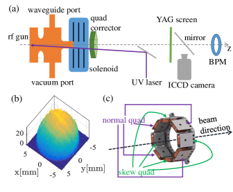
The experimental study was conducted with the L-band 1.6-cell rf photocathode gun at the Argonne Wakefield Accelerator (AWA) facility, as shown in Fig. 1(a). A 248 nm UV laser was applied to generate electrons from the cesium telluride cathode. The laser transverse distribution was homogenized with a microlens array to be relatively uniform Halavanau et al. (2017), as shown in Fig. 1(b). The electric field on the cathode was set to 32 MV/m to reduce the dark current background to facilitate acquiring the low-charge bunch profile on the YAG screen. The electron beam was launched at rf phase and its energy at the gun exit was 3.2 MeV. A solenoid after the gun was used to focus the beam onto a YAG screen perpendicular to the beamline for the emittance measurement. A PI-MAX Intensified CCD (ICCD) camera cam (2004) was used to capture beam images on the retractable YAG screen with a shutter width of 100 ns to improve the signal-to-noise ratio. The spatial resolution of the system was 60 m. A calibrated strip line beam position monitor (BPM) downstream was used to measure the charge with a sensitivity of 40 mV/1 pC.
The solenoid scan technique, in which the measured emittance is determined by fitting the beam size as a function of the solenoid strength Qian et al. (2012); Hauri et al. (2010); Maxson et al. (2017), was used in this research. The solenoid scan range used in this study was only of the average solenoid strength so that the maximum beam size is only about twice the minimum beam size; this reduces the fitting error Qian (2012). Within the small scan range, the variation of the gun quadrupole and solenoid quadrupole can be neglected.
The beam parameters were optimized to minimize in the experiment in order to highlight the coupled aberration. (i) The space charge effect was minimized during the experiment by using a low-charge beam. The charge was gradually reduced until the measured emittance did not change. The charge used in the study was 1 pC for the largest root-mean-square (rms) spot size of 2.7 mm and the charge density was kept the same for smaller sizes. The following parameters were minimized via ASTRA simulations Floettmann et al. . (ii) The emittance growth due to the phase-dependent transverse kick in the rf gun, which is proportional to the beam length Chae et al. (2011), was reduced by using a short beam (1.5 ps FWHM) generated by short laser pulse. Based on simulations, the resulted emittance growth is less than 1.4%. (iii) The low charge and short pulse length yielded a narrow energy spread of 0.1% which contributes only 1.6% emittance growth due to the chromatic aberration according to simulations. (iv) The beam size inside the solenoid was kept under 4 mm, which is much smaller than the 40 mm solenoid bore, so no spherical aberration was observed in simulation. Overall, the total contribution to the measured emittance from other sources is less than 3% and is neglected in the study.
In the first part of the study, the emittance without the quadrupole corrector was measured for various laser spot sizes as shown in Fig. 2. The results can be classified into two regimes: a linear regime where the rms spot size is small (0.75 mm) and a nonlinear regime where the spot size is large (0.75 mm). In the linear regime, the thermal emittance can be estimated to be mm mrad/mm from the slope of the line. This value is consistent with the theoretical estimate via the three-step emission model Flöttmann (1997) by assuming the surface barrier to be 3.5 eV Dowell et al. (2010); Miltchev et al. (2005) and field enhancement factor to be 1 Zheng et al. (2018). In the nonlinear regime, however, the measured emittance deviates from its thermal value as can be observed as the beam size increases. This emittance growth is due to the coupled aberration as expected by Eqn 2. The largest emittance growth reaches 35% with a laser rms spot size of 2.7 mm. The aberration was due to both the gun quadrupole and the solenoid quadrupole. The quadrupole mode of the rf gun has a relative strength of to the monopole mode due to the asymmetric waveguide/vacuum port design. The solenoid has a quadrupole component has a strength of 77 Gauss/m with 0.1974 T solenoid field and a rotation angle of 12 ∘ as previously measured. Zheng et al. (2018).
In the second part of the experiment, a quadrupole corrector was installed at the solenoid exit as illustrated in Fig. 1(a). The corrector consists of a normal and a skew quadrupole, made of eight coils, secured on an aluminum frame wrapped around the beam pipe (Fig. 1(c)). By independently controlling the strength of the two quadrupoles, the corrector’s overall strength and rotation angle can be varied as
| (4) |
where and denotes the strength of the normal and the skew quadrupole, respectively. Here the corrector’s strength can be expressed as , where is the effective length of the quadrupole corrector.
The strength and rotation angle of the quadrupole corrector (Eqn 4) was scanned in order to find the setting that would fully cancel the emittance growth (Fig. 3). The measured emittance oscillates as a function of and emittance reduction is observed when . In Fig. 3(a), the corrector strength is weak (36 Gauss/m) and only one peak around in the range of is observed. On the other hand, in Fig. 3(b) and (c), when the corrector strength is strong (72 and 96 Gauss/m), a second peak appears near . In these cases, the minimum emittance in x-direction reaches the thermal value which demonstrates full cancellation of the emittance growth due to the coupled aberration. However, in the y-direction, although the emittance shows similar trend as the x-direction, its minimum value is larger. In addition, the amplitude of the deviation between the two directions increases with corrector strength. Finally, the quadrupole corrector settings were scanned to fully cancel the aberration for various laser spot sizes. The minimum emittance after optimization is close to the thermal value for all spot sizes as illustrated in Fig. 2.
The emittance measurement results discussed above were benchmarked with ASTRA simulations Floettmann et al. . The simulations included both the gun and solenoid qudrurpole as well as used a realistic laser transverse distribution (Fig. 1(b)). The 3D field map of the photocathode rf gun, including the gun quadrupole component, was simulated with CST Microwave Studio CST and the solenoid quadrupole was modeled as having the same longitudinal profile as the solenoid while its strength and rotation angle were set to the values used during the experiment.
The ASTRA simulation results agree well with the emittance measurements made in both parts of the experiment: without and with the quadrupole corrector. The simulated uncorrected emittance (without the corrector) as a function of laser spot size agrees well with the measurement, as illustrated by the yellow line in Fig. 2. In addition, the simulated emittance as a function of the corrector strength and rotation angle in both the x- and y-directions (Fig. 3, dashed red and blue lines) agrees well with the measured x-direction emittance but has some deviation from the measured y-direction emittance. This may be caused by other mechanisms which are beyond the scope of this paper, such as aberrations from sextupole components Dowell (2018).
In addition to the clear effect the quadrupole corrector had on the measured emittance (see above), it also had a noticeable effect on the transverse profile of the bunch during the solenoid scan, as illustrated in Fig. 4. Without correction (top row) the bunch shape is tilted, which indicates an x-y coupling, as the solenoid strength is scanned. However, at optimized quadruple correction setting, the bunch shape becomes upright and the coupling is eliminated. It should be noted that the shape after correction is not necessarily round, since the corrector does not cancel the aberration locally, but the shape is not tilted. This presents a simple way of finding the proper quadrupole corrector setting without performing the emittance measurements.
In conclusion, a quadrupole corrector was installed on the L-band rf photoinjector at the AWA facility to study the coupled transverse dynamics aberration and to demonstrate elimination of the aberration. An electron bunch with low charge and short length was used to minimize the emittance growth from other sources. The measurement results are in good agreement with theoretical prediction and numerical simulation. The results show that the coupled transverse dynamics aberration from several sources can be fully canceled with a single quadrupole corrector of the proper strength and rotation angle. In summary, this work studied a significant source of emittance growth and demonstrated an effective method for correcting the aberration. These results are expected to benefit the high-brightness, electron-injector-based R&D accelerator community.
Acknowledgements.
This work is supported by the U.S. Department of Energy, Offices of HEP and BES, under Contract No. DE-AC02-06CH11357. It is also funded by the National Natural Science Foundation of China (NSFC) under Grant No. 11435015 and No. 11375097.References
- Emma et al. (2010) P. Emma, R. Akre, J. Arthur, R. Bionta, C. Bostedt, J. Bozek, A. Brachmann, P. Bucksbaum, R. Coffee, F.-J. Decker, et al., Nature Photonics 4, 641 (2010).
- Ackermann et al. (2007) W. Ackermann, G. Asova, V. Ayvazyan, A. Azima, N. Baboi, J. Bähr, V. Balandin, B. Beutner, A. Brandt, A. Bolzmann, et al., Nature Photonics 1, 336 (2007).
- Agapov et al. (2007) I. Agapov, G. Blair, and M. Woodley, Physical Review Special Topics-Accelerators and Beams 10, 112801 (2007).
- Accomando et al. (2004) E. Accomando, A. Aranda, E. Ateser, C. Balazs, D. Bardin, T. Barklow, M. Battaglia, W. Beenakker, S. Berge, G. Blair, et al., arXiv preprint hep-ph/0412251 (2004).
- Weathersby et al. (2015) S. Weathersby, G. Brown, M. Centurion, T. Chase, R. Coffee, J. Corbett, J. Eichner, J. Frisch, A. Fry, M. Gühr, et al., Review of Scientific Instruments 86, 073702 (2015).
- Li et al. (2009a) R. Li, C. Tang, Y. Du, W. Huang, Q. Du, J. Shi, L. Yan, and X. Wang, Review of Scientific Instruments 80, 083303 (2009a).
- Du et al. (2013) Y. Du, L. Yan, J. Hua, Q. Du, Z. Zhang, R. Li, H. Qian, W. Huang, H. Chen, and C. Tang, Review of Scientific Instruments 84, 053301 (2013).
- Gibson et al. (2010) D. Gibson, F. Albert, S. Anderson, S. Betts, M. Messerly, H. Phan, V. Semenov, M. Shverdin, A. Tremaine, F. Hartemann, et al., Physical Review Special Topics-Accelerators and Beams 13, 070703 (2010).
- Limborg-Deprey and Bolton (2006) C. Limborg-Deprey and P. R. Bolton, Nuclear Instruments and Methods in Physics Research Section A: Accelerators, Spectrometers, Detectors and Associated Equipment 557, 106 (2006).
- Chae et al. (2011) M. Chae, J. Hong, Y. Parc, I. S. Ko, S. Park, H. Qian, W. Huang, and C. Tang, Physical Review Special Topics-Accelerators and Beams 14, 104203 (2011).
- Dowell (2016) D. H. Dowell, arXiv preprint arXiv:1610.01242 (2016).
- McDonald and Russell (1989) K. McDonald and D. Russell, Volume 343, 122 (1989).
- Karkare et al. (2017) S. Karkare, J. Feng, X. Chen, W. Wan, F. J. Palomares, T. C. Chiang, and H. A. Padmore, Phys.rev.lett 118 (2017).
- Nemeth et al. (2010) K. Nemeth, K. C. Harkay, V. M. Van, L. Spentzouris, M. White, K. Attenkofer, and G. Srajer, Physical Review Letters 104, 046801 (2010).
- Carlsten (1989) B. E. Carlsten, Nuclear Instruments and Methods in Physics Research Section A: Accelerators, Spectrometers, Detectors and Associated Equipment 285, 313 (1989).
- Zheng et al. (2016) L. Zheng, Y. Du, Z. Zhang, H. Qian, L. Yan, J. Shi, Z. Zhang, Z. Zhou, X. Wu, X. Su, et al., Nuclear Instruments and Methods in Physics Research Section A: Accelerators, Spectrometers, Detectors and Associated Equipment 834, 98 (2016).
- Xiao et al. (2005) L. Xiao, R. F. Boyce, D. H. Dowell, Z. Li, C. Limborg-Deprey, and J. Schmerge, in Proceedings of the Particle Accelerator Conference (2005) pp. 3432–3434.
- Luiten et al. (2004) O. J. Luiten, S. B. V. D. Geer, M. J. D. Loos, F. B. Kiewiet, and M. J. V. D. Wiel, Phys.rev.lett 93, 094802 (2004).
- Li et al. (2009b) Y. Li, S. Chemerisov, and J. Lewellen, Physical Review Special Topics - Accelerators and Beams 12, 64 (2009b).
- Dowell et al. (2018) D. H. Dowell, F. Zhou, and J. Schmerge, Physical Review Accelerators and Beams 21, 010101 (2018).
- Zheng et al. (2018) L. Zheng, J. Shao, Y. Du, J. G. Power, E. E. Wisniewski, W. Liu, C. E. Whiteford, M. Conde, S. Doran, C. Jing, et al., arXiv preprint arXiv:1809.06319 (2018).
- Bartnik et al. (2015) A. Bartnik, C. Gulliford, I. Bazarov, L. Cultera, and B. Dunham, Physical Review Special Topics-Accelerators and Beams 18, 083401 (2015).
- Schietinger et al. (2016) T. Schietinger, M. Pedrozzi, M. Aiba, V. Arsov, S. Bettoni, B. Beutner, M. Calvi, P. Craievich, M. Dehler, F. Frei, et al., Physical Review Accelerators and Beams 19, 100702 (2016).
- Krasilnikov et al. (2018) M. Krasilnikov, I. Isaev, G. Amatuni, G. Asova, P. Boonpornprasert, Y. Chen, J. Good, B. Grigoryan, M. Gross, H. Huck, et al., in 38th Int. Free Electron Laser Conf.(FEL’17), Santa Fe, NM, USA, August 20-25, 2017 (JACOW, Geneva, Switzerland, 2018) pp. 429–431.
- Halavanau et al. (2017) A. Halavanau, G. Qiang, G. Ha, E. Wisniewski, P. Piot, J. Power, and W. Gai, Physical Review Accelerators and Beams 20, 103404 (2017).
- cam (2004) PI-MAX/PI-MAX2 System, Princeton Instruments (2004).
- Qian et al. (2012) H. Qian, C. Li, Y. Du, L. Yan, J. Hua, W. Huang, and C. Tang, Physical Review Special Topics-Accelerators and Beams 15, 040102 (2012).
- Hauri et al. (2010) C. Hauri, R. Ganter, F. Le Pimpec, A. Trisorio, C. Ruchert, and H. Braun, Physical review letters 104, 234802 (2010).
- Maxson et al. (2017) J. Maxson, D. Cesar, G. Calmasini, A. Ody, P. Musumeci, and D. Alesini, Physical review letters 118, 154802 (2017).
- Qian (2012) H. Qian, Research on the Emittance issues of Photocathode RF Gun, Ph.D. thesis, Tsinghua University (2012).
- (31) K. Floettmann et al., http://www.desy.de/mpyflo/ .
- Flöttmann (1997) K. Flöttmann, Note on the thermal emittance of electrons emitted by Cesium Telluride photo cathodes, Tech. Rep. (SCAN-9708052, 1997).
- Dowell et al. (2010) D. Dowell, I. Bazarov, B. Dunham, K. Harkay, C. Hernandez-Garcia, R. Legg, H. Padmore, T. Rao, J. Smedley, and W. Wan, Nuclear Instruments and Methods in Physics Research Section A: Accelerators, Spectrometers, Detectors and Associated Equipment 622, 685 (2010).
- Miltchev et al. (2005) V. Miltchev, J. Baehr, H. Grabosch, J. Han, M. Krasilnikov, and A. Oppelt, in Proceedings of the Free Electron Laser Conference (FEL’05), Stanford, California, USA, August 21-26, 2005 (2005).
- (35) CST Microwave Studio, CST, Bad Nauheimer Str. 19, 64289 Darmstadt, Germany.
- Dowell (2018) D. H. Dowell, arXiv preprint arXiv:1810.00086 (2018).