Controlling light emission by engineering atomic geometries in silicon photonics
Abstract
By engineering atomic geometries composed of nearly 1000 atomic segments embedded in micro-resonators, we observe Bragg resonances induced by the atomic lattice at the telecommunication wavelength. The geometrical arrangement of erbium atoms into a lattice inside a silicon nitride microring resonator reduces the scattering loss at a wavelength commensurate with the lattice. We confirm dependency of light emission to the atomic positions and lattice spacing and also observe Fano interference between resonant modes in the system.
Novel phenomena emerge when resonant modes of a hybrid system undergo coherent interactions Limonov et al. (2017). The interactions of this kind may result in engineering unconventional materials and platforms for broad applications. In photonics, the coherent and cooperative mode coupling has resulted in observation of peculiar effects including Fano interference Limonov et al. (2017), cooperative light scattering, Goban et al. (2015); Sørensen et al. (2016); Corzo et al. (2016), cavity quantum electrodynamic (cQED) interactions Roy et al. (2017); Haroche (2013), Borrmann effect Borrmann (1941); Novikov and Murzina (2017), and topological optical effects Lu et al. (2014); Barik et al. (2018); Mittal et al. (2018). Also, controlling the position of laser-cooled atoms near waveguides and fibers has led to the observation of peculiar effects such as coherent backscatteringSørensen et al. (2016)and superradianceGoban et al. (2015). In a different platform, photon-mediated coupling between a small ensemble of microwave oscillators in a superconducting circuit has been observedMirhosseini et al. (2019). In solid photonics, engineering light-atom interactions to achieve long-range coherent interference in the medium has not been achieved due to the lack of control on atomic positioning. Towards realization of scalable and long-range interference between fields in an atomic ensemble, we study the effect of atomic geometry on photon emission in solid-state photonics. The atoms, in this case, are erbium ions which are rare earth ions with a telecom-band transition embedded in silicon nitride materials. The approach enables study of a novel regime of light-matter interactions in solids by designing the atomic geometry and mode coupling in the system. The relatively low sensitivity of the rare earth (RE) ions to the solid’s environment makes these ions an attractive substance for realization of linear and nonlinear light-matter interactions for quantum applicationsHedges et al. (2010); Saglamyurek et al. (2015); Dibos et al. (2018).
Here, by activation of silicon nitride structures using precision implantation of isotopically pure Er ions, we study coupling between optical and atomic Bragg resonant modes. We observe emission enhancement when the embedded atomic lattice is commensurate with the wavelength of the emitted light. This is because, the emitted light from the atomic lattice gives rise to coherent spatial interference creating a Bragg atomic resonance. On the resonant condition where the emission wavelength is commensurate with the atomic lattice, the scattering loss decreases. Moreover, we record asymmetric lineshapes of photon emission governed by Fano interference between the resonant modes of the system. In this way, we take advantage of the inhomogeneous broadening of ions in silicon nitride to enhance collection of radiation at a desired wavelength within the emission band of the Er ions.
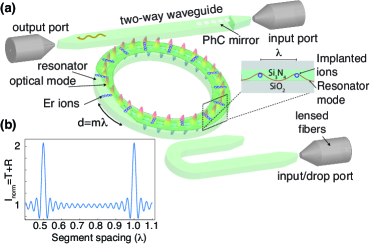
We use isotopically pure 168Er ions directly implanted in a SiN microring resonator into a periodic array (atomic lattice) (see Fig.1(a) ). Considering an array of ion segments (with the width of each segment being much smaller than the wavelength) implanted in a ring resonator, the emission from the ion array can be approximately described by a 1D theory of atoms coupled to a waveguide. We study the interaction dynamics by numerically solving the semiclassical Maxwell-Bloch equations of motion. The equations of motion capturing the interaction of light with an ensemble of atoms in free space are
| (1) | |||||
| (2) |
where is the expected value of the forward/backward intra-cavity electric field operator, is a function describing the linear atomic density, is the amplitude of the atomic polarization in a two-level atom, is the docoherence rate which includes both population decay rate () and excess dephasing () and is the light-atom coupling rate. The inhomogeneous broadening of the atomic transition is described by . We numerically solve these equations for various atom spacing. The result for emission from the array is shown in Fig.1(b) as a function of the atomic spacing. The maximum intensity is observed when the atom spacing is a multiple of half of the resonant wavelength. This is consistent with the free-space Bragg theoryDeutsch et al. (1995). In the case of a continuously driven ring resonator and in the limit of , the cavity field with decay rate can be adiabatically eliminated with light-atom dynamics approximately described by Eqs.(1)-(2). The mode mixing Chang et al. (2019); Feng et al. (2014) and coherent interference in the spatially ordered lattice Deutsch et al. (1995) in the ring resonator gives rise to a standing wave structure for the scattered light Slama et al. (2006). The atomic lattice acts as a Bragg grating Sørensen et al. (2016) scattering light in both directions with probability , where is the effective ratio of scattering into the resonator mode by the ensemble of the atomic segments Furuya et al. (2020), , to that of free space, , and is the effective atom number contributing to the scattering process. Compared to the free-space case, is enhanced in the ring by a factor of Tanji-Suzuki et al. (2011), where is the equivalent resonator finesse. With standing wave nodes of the scattered light at the position of the atoms, the scattering loss is expected to reduceDeutsch et al. (1995). We note that reduction in scattering occurs in all directions due to lower field intensity at the location of the atoms. This is different from Purcell enhancement or superradiance because the cavity effect induced by the atoms is not strong enough, or atomic coherence is not long enough, to affect the spontaneous emission rate. The enhanced photoluminescence is because of the reduction in scattering loss imposed by the Bragg resonance. The scattering loss from the ensemble is approximately given by , for an optically thin ensemble. In an optically thick sample, multiple reflections give rise to radiation trapping and scattering loss, which can still be significantly less than the case of random atomic distributionDeutsch et al. (1995).
To experimentally study the effects described above, we fabricate microring resonators using a 500nm thick SiN layer on SiO2. The width and diameter of the ring is 1.5 m and 150m, respectively. Er ions were implanted into an ion array, separated by an integer number of the Er emission wavelength, with a precision of 10nm at the Sandia National Laboratories. The energy used for the implantation was 200 keV with implantation depth of 50nm. About ions were implanted in a rectangular area of width 20nm along the radius of the ring. The sample was then annealed at 1100°C for one hour in nitrogen flow of 5.0 standard liter per minute (SLPM). A polymer (PMMA) layer of around 1 m thick was spin coated on the sample as an upper-cladding after annealing for better mode confinement and also to fine tune the effective index of the optical mode by varying the thickness of this layer. The sample was placed inside a cryostat with typical temperature of 4K with two optical fibers directing light to/from the sample from/to the room-temperature setup outside the cryostat for measurement. The atoms were resonantly excited by a tunable diode laser. Typical input power of the pump in the experiments was around 5 , below the saturation limit of the erbium ions. Two AOMs were used to create a pulse to pump the atoms for 6ms and turn it off for 10-15ms during the photoluminescence (PL) measurement. The PL light was detected using a single photon detector and counts were averaged over runs.
For measuring the emission spectrum, we test three ring resonators, ringA, ringB and ringC with 980, 245 and 327 atomic segment numbers, respectively. The bus waveguide is designed to maximally transmit the TM polarization by tapering the waveguide at the fiber-waveguide interface. Due to the large width of the resonator, TM1 mode is efficiently coupled to the resonator with more than 60% coupling efficiency having a loaded Q factor of about . The calculated effective index for ringA and ringB for this mode is about 1.58. Considering this effective index, the Bragg resonance condition is satisfied at about 1520nm when the atomic lattice spacing is an integer multiple of nm. We refer to this as “commensurate lattice (CL)” at around 1520nm. For ringC, we removed the PMMA layer on the SiN ring resonator. So, the calculated effective index for ringC for this mode is about , which, in theory, shifts the resonance condition to lower wavelengths ( 1508nm). We refer to this as “incommensurate lattice (iCL)” condition where the emission wavelength centered within the Er emission band does not match the lattice spacing. The lowest wavelength that could be reached with our laser is 1510nm. We also note that the implantation of Er ions and annealing conditions for the CL and iCL samples were done under the same conditions and the only difference is the PMMA upper cladding layer and thus the observed effect can not be explained by presence of implantation damageSobolev et al. (1998); Kenyon (2005). The fact that host is amorphous and emission shows pump-power dependency and long-lifetime (corresponding to erbium ions) confirms that the enhanced emission is not caused by defects in the hosts.
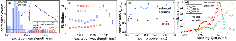
The emitted mean photon number is measured at every free-spectral range of the cavity. The resulted emission spectrum at 4K temperature is shown in Fig.2 (a). The spectrum significantly deviates from the emission of the ions at room temperature. The observed peak emission near 1518nm corresponds to a commensurate lattice with 962nm spacing between implanted segments. Assuming an effective index of 1.578, the result is in agreement with the calculated resonant wavelength value. Taking into the account our experimental parameters including the spatial atomic distribution width (20nm), inhomogeneous broadening (3nm), total atom number (), yield factor of the implantation (10%), branching ratio in Er ions (0.1), and ion-cavity field overlap (0.5), the estimated is about 50. The scattering loss in this limit can be numerically calculated where signifiant enhancement is expectedDeutsch et al. (1995). The result in Fig.2 (a) shows an enhancement of ¿30, in broad agreement with the Bragg theory.
As temperature increases the PL ratio decreases suggesting suppression of the emission near the Bragg resonance . This is because of increase in homogenous broadening and phonon-assisted excitations Miyakawa and Dexter (1970) (confirmed by observation of increased absolute emission intensity with temperature rise) at elevated temperatures. The emission ratio is plotted versus temperature as an inset to Fig2.(a). The expected homogenous linewidth, , in amorphous hosts like silicon nitride is expected to exceed the cavity linewidth, , at higher temperaturesGong and et
al. (2010) causing to decrease. Moreover, presence of phonon-assisted excitation and also increased inhomogeneous broadening contribute to the reduction of the as the temperature increases. Consequently, the spatial interference and the Bragg resonance effect from the atoms is suppressed at elevated temperatures. It should be noted, that even though we observe enhanced Bragg effect from the ensemble at low temperatures, the single-atom cooperativity is not large enough to alter the atomic decay rate.
The emission decay time measured at different wavelengths (Fig.2 (b)) shows lengthening of the lifetime at low temperatures, which we associate to suppression of non-radiative decay. The lengthened decay time around 1535 nm is due to the reabsorption SUMIDA and FAN (1994) (radiation trapping) at the peak (regular) emission wavelength where more atoms exist. The negligible lifetime change around 1520nm ruling out the possibility of dominant superradiance emission from the ions near the atomic Bragg resonance condition.
We plot light intensity at around 1521nm ( emission near the Bragg resonance ) relative to that of 1532nm (near regular emission peak). Figure 2 (c) shows that beyond some pump power, the emission overcomes the re-absorption and enhanced emission is evidenced. Such enhanced emission is absent for the iCL as the emission signal over the entire spectrum linearly changes with the atom number. At high pump powers, the PL eventually saturates for both transitions.
Figure 2(d) shows the total photons emitted from the ions in ringA, ringB and ringC as a function of the spacing parameter, , where . As ringA and ringB consists of a CL at around 1520nm, we see the enhanced emission near that wavelength. Whereas, for ringC, the Bragg resonance is shifted to lower wavelengths. The center peak () corresponds to the regular emission around 1532 nm, which is inhomogeneously broadened. We use a Gaussian function to model the emission centered around 1532nm with a full inhomogeneous width of about nm. The linewidth of the enahnced emission peak is governed by atomic spatial distribution (with a Gaussian width of around 40nm), inhomogeneous broadening of the atomic transitions (around 3nm) and number of atoms. We note that although the number of ions for ringC is more than ringB, the effective atom number, taking into the account the Er atomic transition, is less for ringC giving rise to its broader emission peak. By comparing the fitted amplitudes of the Gaussian (describing PL emission around 1532nm) and Lorentzian distribution (describing the enhanced emission around 1520nm) functions we observe nonlinear dependence of the relative emission to the atom number. For an iCL, the ratio between the two emission peaks (around 1520nm and 1532nm) is independent of the atom number. This is evidenced in Fig. 2(c) where power is a proxy for atom number. We observe that the ratio between the emission near the Bragg resonance and regular PL emission scales nonlinearly with the number of atomic segments. In the case of data in Fig. 2(d), the resonator with (ringA) has four times more atoms compared to the resonator with (ringB). Using the values extracted from the model plotted in Fig. 2(d) we infer a ratio of about 2.4 between the emission near the Bragg resonance and the regular emission.
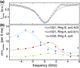
Moreover, the presence of atomic Bragg condition suggests the possibility of mode interference and appearance of Fano-type resonances in the systemLimonov et al. (2017). In our system, the coupling between the atomic Bragg mode (continuum mode) and the ring resonator (discrete mode) gives rise to asymmetric emission lines, where phase change of the atomic mode happens very slowly compared to the ring resonator mode. The asymmetry in the lineshape is characterized by the Fano parameter , where is the phase shift of the atomic mode with respect to the cavity mode. This is evidenced by the observed lineshapes in Fig. 3(a) and 3(b). A non-zero Fano parameter is fitted to the emission spectrum centered around 1520nm for both ringA and ringB while the emission spectrum around 1532nm (green data) is described by a symmetric Lorentzian function. To obtain this data, we collect PL from the ions after pump excitation at different frequencies around a single cavity resonance near 1520 nm and 1532 nm.
In conclusion, we design atomic geometries of erbium ions inside a silicon nitride micro-photonic resonator and study the effect of geometry on light-atom coupling from the ensemble. We observe that spatial interference at low temperatures from a lattice of ions creates a Bragg atomic resonance enhancing the emission. The interference between the optical and atomic Bragg modes is also observed through Fano-type resonance features. The investigation offers a unique path to further engineer active silicon photonic structures for studying cQED interactions between atoms and photons in an ensemble Chang et al. (2018, 2019), on-chip photon generationBarik et al. (2018); Furuya et al. (2020), and engineering non-Hermitian Hamiltonians Feng et al. (2014).
Funding. Tellabs Foundation; Center for Integrated Nanotechnologies; U.S. Department of Energy (DE-NA-0003525); Sandia National Laboratories .
Acknowledgment. The views expressed here do not necessarily represent the views of DOE or the U. S. Government. M.H. thanks A. Weiner and C.-L. Hung for the enlightening discussions.
References
- Limonov et al. (2017) M. F. Limonov, M. V. Rybin, A. N. Poddubny, and Y. S. Kivshar, Nature Photonics 11, 543 (2017).
- Goban et al. (2015) A. Goban, C.-L. Hung, J. Hood, S.-P. Yu, J. Muniz, O. Painter, and H. Kimble, Physical review letters 115, 063601 (2015).
- Sørensen et al. (2016) H. Sørensen, J.-B. Béguin, K. Kluge, I. Iakoupov, A. Sørensen, J. Müller, E. Polzik, and J. Appel, Physical review letters 117, 133604 (2016).
- Corzo et al. (2016) N. V. Corzo, B. Gouraud, A. Chandra, A. Goban, A. S. Sheremet, D. V. Kupriyanov, and J. Laurat, Phys. Rev. Lett. 117 (2016), 10.1103/PhysRevLett.117.133603.
- Roy et al. (2017) D. Roy, C. M. Wilson, and O. Firstenberg, Rev. Mod. Phys. 89 (2017).
- Haroche (2013) S. Haroche, Rev. Mod. Phys. 85, 1083 (2013).
- Borrmann (1941) G. Borrmann, Zeitschrift für Physik 42, 157 (1941).
- Novikov and Murzina (2017) V. Novikov and T. Murzina, Optics letters 42, 1389 (2017).
- Lu et al. (2014) L. Lu, J. D. Joannopoulos, and M. Soljacic, Nat. Photonics 8, 821 (2014).
- Barik et al. (2018) S. Barik, A. Karasahin, C. Flower, T. Cai, H. Miyake, W. DeGottardi, M. Hafezi, and E. Waks, Science 359, 666 (2018).
- Mittal et al. (2018) S. Mittal, E. A. Goldschmidt, and M. Hafezi, Nature 561, 502 (2018).
- Mirhosseini et al. (2019) M. Mirhosseini, E. Kim, X. Zhang, A. Sipahigil, P. B. Dieterle, A. J. Keller, A. Asenjo-Garcia, D. E. Chang, and O. Painter, Nature 569, 692 (2019).
- Hedges et al. (2010) M. Hedges, J. Longdell, Y. Li, and M. Sellars, Nature 465, 1052 (2010).
- Saglamyurek et al. (2015) E. Saglamyurek, J. Jin, V. B. Verma, M. D. Shaw, F. Marsili, S. W. Nam, D. Oblak, and W. Tittel, Nat. Phot. 9, 83 (2015).
- Dibos et al. (2018) M. Dibos, M. Raha, C. M. Phenicie, and J. D. Thompson, Phys. Rev. Lett. 120 (2018).
- Deutsch et al. (1995) I. H. Deutsch, R. J. C. Spreeuw, S. L. Rolston, and W. D. Phillips, Phys. Rev. A 52, 1394 (1995).
- Chang et al. (2019) T.-H. Chang, B. M. Fields, M. E. Kim, and C.-L. Hung, Optica 6, 1203 (2019).
- Feng et al. (2014) L. Feng, Z. J. Wong, R.-M. Ma, Y. Wang, and X. Zhang, Science 346, 972 (2014).
- Slama et al. (2006) S. Slama, C. von Cube, M. Kohler, C. Zimmermann, and P. W. Courteille, Phys. Rev. A 73 (2006), 10.1103/PhysRevA.73.023424.
- Furuya et al. (2020) K. Furuya, A. Nandi, and M. Hosseini, Optical Materials Express 10, 577 (2020).
- Tanji-Suzuki et al. (2011) H. Tanji-Suzuki, I. D. Leroux, M. H. Schleier-Smith, M. Cetina, A. Griera, J. Simon, and V. Vuletić, Adv. At. Mol. Opt. 60, 201 (2011).
- Sobolev et al. (1998) N. Sobolev, O. Gusev, E. Shek, V. Vdovin, T. Yugova, and A. Emel’yanov, Journal of luminescence 80, 357 (1998).
- Kenyon (2005) A. Kenyon, Semiconductor Science and Technology 20, R65 (2005).
- Miyakawa and Dexter (1970) T. Miyakawa and D. Dexter, Physical Review B 1, 2961 (1970).
- Gong and et al. (2010) Y. Gong and et al., Opt. Exp. 18, 2601 (2010).
- SUMIDA and FAN (1994) D. S. SUMIDA and T. Y. FAN, Opt. Lett. 19, 1343 (1994).
- Chang et al. (2018) D. E. Chang, J. S. Douglas, A. Gonzalez-Tudela, C. L. Hung, and H. J. Kimble, Rev. Mod. Phys. 90 (2018).