Giant spin-orbit torque in a single ferrimagnetic metal layer
Abstract
Antiferromagnets and compensated ferrimagnets offer opportunities to investigate spin dynamics in the ‘terahertz gap’ because their resonance modes lie in the range. Despite some inherent advantages when compared to ferromagnets, these materials have not been extensively studied due to difficulties in exciting and detecting the high-frequency spin dynamics, especially in thin films. Here we show that spin-orbit torque in a single layer of the highly spin-polarized compensated ferrimagnet Mn2RuxGa is remarkably efficient at generating spin-orbit fields , which approach in the low-current density limit – almost a thousand times the Oersted field, and one to two orders of magnitude greater than the effective fields in heavy metal/ferromagnet bilayers.
We depend on fast, reliable exchange of information across long distances through intercontinental optical fibres, as well as short-distance connections between the central processing unit of a computer and its memory. The latter is the bottleneck to the powerful computing facilities needed in a future where machine learning and algorithms aid our daily lives. This bottleneck is difficult to overcome because electronics lack a practical chip-based solution to produce and detect electromagnetic waves in the spectral range between known as the terahertz gap.
Slonczewski (1989) realised that angular momentum could be transferred from one magnetic layer (a polariser) to another (the analyser) by a spin polarised current.Slonczewski (1996) This spin-transfer torque has enabled the scaling of devices that depend on the relative magnetic orientation of two ferromagnetic layers.Chappert et al. (2007)
Spin electronics exploiting the orbital degree of freedom of the electron is a recent development. A major advance was the discovery that the angular momentum could be supplied by a diffusive spin currentMiron et al. (2011); Liu et al. (2012) created via the spin Hall effectD’yakonov and Perel (1971); Hirsch (1999) in a non-magnetic heavy metal layer adjacent to the ferromagnet. Devices based on these bilayers require a bare minimum of two layers on a substrate. Earlier, Dresselhaus (1955) and Bychkov and Rashba (1984) had shown that in crystalline or patterned structures lacking inversion symmetry, a current-induced spin polarisation (CISP) is a direct consequence of the symmetry of the band structure. This idea was developed by Železný et al. (2014)Železný et al. (2017) to predict the form of the tensor relating the charge current to the CISP in crystals of different symmetry. switching of the metallic antiferromagnets CuMnAsWadley et al. (2016) and Mn2AuBodnar et al. (2018) was subsequently observed. These ground-breaking results established the existence of a current-induced, field-like (or reactive) torque, and allow an estimate of the strength of the effective magnetic field by comparing it to the in-plane magnetic anisotropy of the material.
Hitherto there has been no quantitative measurement of the anti-damping (or dissipative) spin-orbit torque in homogeneously magnetised ferrimagnetic or antiferromagnetic single-layer samples. Here we show, via harmonic analysis of the anomalous Hall effect,Hayashi et al. (2014) that in a single layer of the prototype half-metallic compensated ferrimagnet Mn2RuxGa with (MRG),Kurt et al. (2014); Thiyagarajah et al. (2015); Žic et al. (2016); Borisov et al. (2016); Betto et al. (2016, 2015); Borisov et al. (2017) both the field- and damping-like components of the torque reach record values, almost two orders of magnitude stronger than those obtained in the bilayer ferromagnet/heavy metal systems, or in metallic ferromagnetsCiccarelli et al. (2016) and semimagnetic semiconductorsKurebayashi et al. (2014). The record values of the single-layer SOT and the dominance of the dissipative torque, open a path to sustaining magnetic oscillations in the terahertz gap.
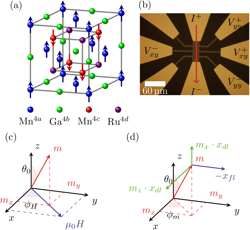
Thin-film samples of MRG grown on MgO by DC-magnetron sputtering from stoichiometric targets crystallise in a Heusler-like structure, space group illustrated in Figure 1a, where the conduction bands originate predominantly from Mn in sites.Betto et al. (2015) The films are patterned into the micron-sized Hall bar structures shown in Figure 1b, where the bias current is parallel to the MRG axis. Further details on sample growth can be found in the supplementary material and [Betto et al., 2016]. We determine the current-induced effective fields via the anomalous Hall effect (AHE), assuming it is proportional to the component of the magnetisation of the Mn4c sublattice. Due to the substrate-induced biaxial strain, the point group of Mn in this position is reduced from to . Here we restrict our analysis to the effect on one sublattice, as the other will follow via inter-sublattice exchange with a phase-lag. We treat all effective torques as equivalent to external applied fields. For an in-plane applied field , the magnetisation is described by the polar and azimuthal angles and , with the latter taken to be equal to the azimuthal angle of the applied field because the four-fold in-plane anisotropy is weak compared with the uniaxial perpendicular anisotropy. The coordinates describing the magnetic state are shown in Figure 1c. In the presence of a unit charge current density , the CISP produces a SOT effective field (see Figure 1d):
| (1) |
where are unit vectors, are the components of the unit magnetisation vector, and , are the coefficients of the field- and damping-like contributions to the spin-orbit field, respectively. The units of , and are then . Henry is an equivalent unit. When the bias current has an alternating component () we detect the effect of the CISP on both the second and the third harmonic response using lock-in demodulation. The conversion from the voltages detected at the different harmonics to the magnitude of the effective fields is detailed in the supplementary material. In Table 1 we indicate the symmetry of the different contributions to in the first, second and third harmonic responses. Contributions from the anomalous Nernst effect (ANE) are suppressed by measuring or by taking the difference of measured with positive and negative DC bias. The contribution from the homogeneous temperature variation oscillating at twice the applied frequency is determined from data in Figure 2, as explained in the supplementary material.
| Contribution/Harmonic | |||
|---|---|---|---|
| Anomalous Hall Effect: | o | - | - |
| Anomalous Nernst Effect: | - | v | - |
| Homogeneous oscillating at : | v | / | o |
| Current-induced fields: | / v | / | o |
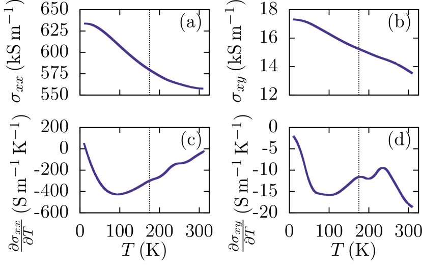
Figure 2 shows the temperature dependence of the longitudinal and transverse conductivity of MRG, recorded in the remnant state after saturation in a positive field at room temperature. The conductivity (Figure 2a) increases with decreasing , and its saturation value of or corresponds to the minimum metallic conductivity of a bad metal where the mean free path is comparable to the interatomic spacing.Mott (1990) The Hall conductivity (Figure 2b) closely follows the Mn4c sublattice magnetisation.Fowley et al. (2018a) The lower panels show the temperature-derivatives of .
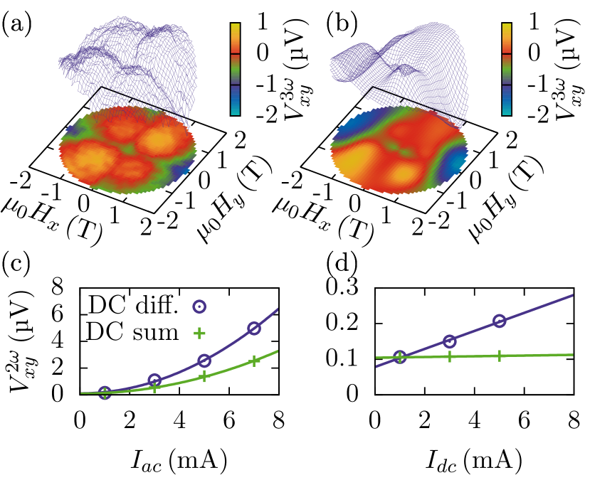
We now turn to the SOT. Figure 3 a and b shows the experimentally observed and its calculated values based on the experimental . There is excellent agreement between experiment and the model, which is based only on the site symmetry, the data in Figure 2, and the first harmonic response (used to determine and the anisotropy constants). All the features in both the and dependencies are well reproduced: two deep minima around , four maxima that align with the four-fold in-plane anisotropy due to the small value of the in-plane anisotropy constant , as well as a weaker central minimum at small fields. Qualitatively, the field-dependence of the SOT can be understood by comparing equation (1) with Figure 3 (a), and noting that the magnitude of depends not only on itself, but explicitly on the competition between the SOT field, the anisotropy field and the applied field. At low applied fields () the current-driven wobble of is determined by a combination of the anisotropy and SOT fields. is small, however, because , hence the central minimum is shallow. At higher applied fields, deviates from 0, but the SOT field now has to compete with both the (higher) anisotropy field and the Zeeman torque provided by the applied field acting on the net magnetisation. This gives rise to the characteristic four-fold signal. An exceptional feature appears around where the damping-like field in the direction scaling as produces a field strong enough to dwarf both the anisotropy field and the applied field. We emphasise not only the qualitative agreement, but also that the absolute magnitude of the signal agrees very well with the model when we fit the coefficients of the field- and damping-like fields; and .
We then determine the dependence of the effective field magnitude on bias current, (Figure 3 c and d). A current of in our films is equivalent to of about . We expect due to SOT to scale with and , while the effects due to thermal gradients should be independent of and scale as . Indeed, the DC difference is quadratic in (Figure 3c) and linear in (Figure 3d), while the DC sum is quadratic in and practically independent of .
It is instructive to compare the effective fields due to intrinsic SOT with those recorded on conventional bilayers of a heavy metal (typically Pt, Ta or W) and a ferromagnet (typically Co, Fe, CoFe or CoFeB). For bilayers, the damping-like effective field per current density can be written: , where is the spin-Hall angle of the heavy metal, is the Planck’s constant, is the electron charge, the magnetisation of the ferromagnet and its thickness. For of CoFeB (), which has a magnetic moment equivalent to that of nearly compensated MRG, and we obtain an effective, damping-like field of (). We would need a fictitious spin-Hall angle of to match the value of the field-like term in MRG and to match the damping-like term.
This comparison highlights the inherent advantage of using ferrimagnets in combination with intrinsic SOT. In a bilayer, increasing the thickness of the ferromagnet beyond the spin diffusion length (typically ), does not produce any additional torque. If the ferromagnet is rather than thick, the effective field may be reduced to half, whereas the field in single-layer MRG is unchanged with thickness. The volume of MRG can be scaled up or down without changing the torque, providing the current density is constant. The nature of the intrinsic torque is staggered acting directly on the Mn4c sublattice, hence a more correct comparison might be be to normalise the spin Hall angle using the sublattice magnetisation, which is approximately ten times greater than the net magnetisation at room temperature for the present sample. Furthermore, the torque is maintained even in the absence of any net magnetisation at the ferrimagnetic compensation temperature, thus permitting GMR- and TMR-based device structures to be excited by SOT even in the absence of any net moment of the free layer. This enables targeted control of the dynamics, and the excitation of both in-and out-of phase resonance modes.
The high effective fields found above assuming small, linear, current-driven variations in , imply that the action of the SOT should also be observable in the non-linear transfer characteristics of our Hall bar device. We therefore proceeded as follows:
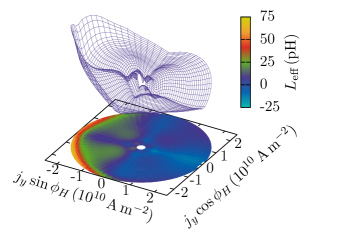
We first recorded a full field-in-plane hysteresis loop from to determine the relation between and the applied field and invert this relation numerically, to be able to deduce, from , the value of the total effective field at any given applied current. Then, a constant external field is applied in the sample plane and rotated around , changing the azimuthal angle from while recording (inferred from ). This measurement is repeated for range of current densities from . As the action of the SOT field depends directly on its direction relative to the direction of the magnetisation ( and ), we can subtract any variation that is -independent. This -independent effective field contains all variations that are due to heating. The result, after subtraction, is shown in Figure 4, where we give the effective field in terms of the effective, current-induced inductance in . A current density of can produce an effective inductance , equivalent to an effective in-plane field of ! We note that this field is sufficient to magnetically switch of the sample.
We make two important comments on this analysis. First, by removing the -independent part of the signal, we also remove any SOT that behaves the same way. If we again assume the SOT fields can be described by the tensors reported by Železný et al. (2017) and Troncoso et al. (2019), and expand the relation between and to second order in , we find that we have removed a damping-like contribution along that varies as , which may be considerable. Second, as we are normalising with respect to the action of the external, in-plane, field, the SOT effective field directed along , remaining after the procedure outlined above, contributes to our signal as seen by the upturn at in Figure 4.
The strong effective SOT fields in MRG are related to its high anomalous Hall angle.Thiyagarajah et al. (2015) The value is unusual in the sense that MRG does not contain any elements heavier than Ru; in any case the AHE angle does not scale with Ru content . Furthermore the conduction electrons in MRG are predominantly -like, although it has been suggested that Ga in the Mn-containing Heuslers lends some character to the bands at the Fermi-level through hybridisation, increasing the spin-orbit coupling of the conduction electronsLau et al. (2019). We have already seen above that MRG is at the limit of metallic conductivity. From our measurements of and , we can deduce the spin-orbit scattering cross-section and find that it corresponds to of the unit cell surface area. The very large scattering cross section is consistent with the very short mean free path.
So far we have demonstrated high current-induced effective fields as well as a high ratio () of the dissipative (anti-damping) to the reactive (field-like) torques. This will allow for the realization of more efficient magnetic switchingGarello et al. (2014), exchange-bias manipulationLin et al. (2019) as well as low-current control of magnetic texturesHals and Brataas (2014). The key question is, whether sustained self oscillation can be driven by SOT. We address this from two different angles, first by considering the results established by Troncoso et al. (2019), noting that the effective fields will act distinctly on the magnetisation and the Néel vectors. Using the numerical values of the effective fields found in the linear, low-current regime, self-oscillations will emerge for current densities that provide a reactive torque which is sufficient to overcome the in-plane anisotropy for MRG, which corresponds to . The second necessary condition is that the dissipative torque must overcome the Gilbert damping . Taking we find the condition . An alternative approach is to compare directly the effective inductance created by the SOT and the self inductance of the oscillating element. In a shorted Hall bar device, a crude estimate of the self inductance for a thick film with an active length of is – the dimensions are chosen to enhance impedance matching to free space in a real oscillator. We saw in Figure 4 that the effective inductance reaches values two orders of magnitude higher than this, ensuring that oscillatory behaviour is possible, even in the low-current-density region. The natural frequency of the oscillator will be determined by the larger of the two effective inductances, that is by the SOT and the magnetic resonance frequency of the material, which we previously estimated as .Fowley et al. (2018b)
In summary, we find that current-induced spin orbit torque reaches record values in single-layers of the compensated, half-metallic ferrimagnet Mn2RuxGa, well in excess of those achieved in bilayer structures. With realistic values of damping, this should allow sustained magnetic oscillations that could be detected by magnetoresistive effects, or free-space emission using a suitable antenna. A cheap, compact, and tunable oscillator operating in the terahertz gap would break new ground in spin dynamics, and could potentially unlock a new realm of information transfer at bandwidths three orders of magnitude higher than those of the present day.
Acknowledgements.
This project has received funding from the European Union’s Horizon 2020 research and innovation programme under grant agreement No 737038, and from Science Foundation Ireland through contracts 12/RC/2278 AMBER and 16/IA/4534 ZEMS as well as the Research Council of Norway through its Centres of Excellence funding scheme, Project No. 262633 “QuSpin”. The authors declare no competing financial interests.References
- Slonczewski (1989) J. C. Slonczewski, Phys. Rev. B 39, 6995 (1989).
- Slonczewski (1996) J. Slonczewski, J. Mag. Magn. Mat. 159, L1 (1996).
- Chappert et al. (2007) C. Chappert, A. Fert, and F. N. Van Dau, Nature Materials 6, 813 (2007), review Article.
- Miron et al. (2011) I. M. Miron, K. Garello, G. Gaudin, P.-J. Zermatten, M. V. Costache, S. Auffret, S. Bandiera, B. Rodmacq, A. Schuhl, and P. Gambardella, Nature 476, 189 (2011).
- Liu et al. (2012) L. Liu, C.-F. Pai, Y. Li, H. W. Tseng, D. C. Ralph, and R. A. Buhrman, Science 336, 555 (2012).
- D’yakonov and Perel (1971) M. D’yakonov and V. Perel, Soviet Journal of Experimental and Theoretical Physics Letters 13, 467 (1971).
- Hirsch (1999) J. E. Hirsch, Phys. Rev. Lett. 83, 1834 (1999).
- Dresselhaus (1955) G. Dresselhaus, Phys. Rev. 100, 580 (1955).
- Bychkov and Rashba (1984) Y. A. Bychkov and E. I. Rashba, JETP lett 39, 78 (1984).
- Železný et al. (2014) J. Železný, H. Gao, K. Výborný, J. Zemen, J. Mašek, A. Manchon, J. Wunderlich, J. Sinova, and T. Jungwirth, Phys. Rev. Lett. 113, 157201 (2014).
- Železný et al. (2017) J. Železný, H. Gao, A. Manchon, F. Freimuth, Y. Mokrousov, J. Zemen, J. Mašek, J. Sinova, and T. Jungwirth, Phys. Rev. B 95, 014403 (2017).
- Wadley et al. (2016) P. Wadley et al., Science 351, 587 (2016).
- Bodnar et al. (2018) S. Y. Bodnar, L. Smejkal, I. Turek, T. Jungwirth, O. Gomonay, J. Sinova, A. A. Sapozhnik, H. J. Elmers, M. Klaui, and M. Jourdan, Nature Communications 9, 348 (2018).
- Hayashi et al. (2014) M. Hayashi, J. Kim, M. Yamanouchi, and H. Ohno, Phys. Rev. B 89, 144425 (2014).
- Kurt et al. (2014) H. Kurt, K. Rode, P. Stamenov, M. Venkatesan, Y.-C. Lau, E. Fonda, and J. M. D. Coey, Phys. Rev. Lett. 112, 027201 (2014).
- Thiyagarajah et al. (2015) N. Thiyagarajah, Y.-C. Lau, D. Betto, K. Borisov, J. Coey, P. Stamenov, and K. Rode, Appl. Phys. Lett. 106, 122402 (2015).
- Žic et al. (2016) M. Žic, K. Rode, N. Thiyagarajah, Y.-C. Lau, D. Betto, J. M. D. Coey, S. Sanvito, K. J. O’Shea, C. A. Ferguson, D. A. MacLaren, and T. Archer, Phys. Rev. B 93, 140202 (2016).
- Borisov et al. (2016) K. Borisov, D. Betto, Y.-C. Lau, C. Fowley, A. Titova, N. Thiyagarajah, G. Atcheson, J. Lindner, A. M. Deac, J. M. D. Coey, P. Stamenov, and K. Rode, Appl. Phys. Lett. 108, 192407 (2016), 10.1063/1.4948934.
- Betto et al. (2016) D. Betto, K. Rode, N. Thiyagarajah, Y.-C. Lau, K. Borisov, G. Atcheson, M. Žic, T. Archer, P. Stamenov, and J. M. D. Coey, AIP Adv. 6, 055601 (2016), 10.1063/1.4943756.
- Betto et al. (2015) D. Betto, N. Thiyagarajah, Y.-C. Lau, C. Piamonteze, M.-A. Arrio, P. Stamenov, J. Coey, and K. Rode, Phys. Rev. B 91, 094410 (2015).
- Borisov et al. (2017) K. Borisov, G. Atcheson, G. D’Arcy, Y.-C. Lau, J. M. D. Coey, and K. Rode, Applied Physics Letters 111, 102403 (2017), https://doi.org/10.1063/1.5001172 .
- Ciccarelli et al. (2016) C. Ciccarelli, L. Anderson, V. Tshitoyan, A. J. Ferguson, F. Gerhard, C. Gould, L. W. Molenkamp, J. Gayles, J. Zelezný, L. Smejkal, Z. Yuan, J. Sinova, F. Freimuth, and T. Jungwirth, Nature Physics 12, 855 (2016).
- Kurebayashi et al. (2014) H. Kurebayashi, J. Sinova, D. Fang, A. C. Irvine, T. D. Skinner, J. Wunderlich, V. Novák, R. P. Campion, B. L. Gallagher, E. K. Vehstedt, L. P. Zârbo, K. Výborný, A. J. Ferguson, and T. Jungwirth, Nature Nanotechnology 9, 211 (2014).
- Mott (1990) N. Mott, Metal-insulator transitions (CRC Press, 1990).
- Fowley et al. (2018a) C. Fowley, K. Rode, Y.-C. Lau, N. Thiyagarajah, D. Betto, K. Borisov, G. Atcheson, E. Kampert, Z. Wang, Y. Yuan, S. Zhou, J. Lindner, P. Stamenov, J. M. D. Coey, and A. M. Deac, Phys. Rev. B 98, 220406 (2018a).
- Troncoso et al. (2019) R. E. Troncoso, K. Rode, P. Stamenov, J. M. D. Coey, and A. Brataas, Phys. Rev. B 99, 054433 (2019).
- Lau et al. (2019) Y.-C. Lau, H. Lee, G. Qu, K. Nakamura, and M. Hayashi, Phys. Rev. B 99, 064410 (2019).
- Garello et al. (2014) K. Garello, C. O. Avci, I. M. Miron, M. Baumgartner, A. Ghosh, S. Auffret, O. Boulle, G. Gaudin, and P. Gambardella, Applied Physics Letters 105, 212402 (2014).
- Lin et al. (2019) P.-H. Lin, B.-Y. Yang, M.-H. Tsai, P.-C. Chen, K.-F. Huang, H.-H. Lin, and C.-H. Lai, Nature Materials (2019), 10.1038/s41563-019-0289-4.
- Hals and Brataas (2014) K. M. D. Hals and A. Brataas, Phys. Rev. B 89, 064426 (2014).
- Fowley et al. (2018b) C. Fowley, K. Rode, Y.-C. Lau, N. Thiyagarajah, D. Betto, K. Borisov, G. Atcheson, E. Kampert, Z. Wang, Y. Yuan, S. Zhou, J. Lindner, P. Stamenov, J. M. D. Coey, and A. M. Deac, Phys. Rev. B 98, 220406 (2018b).