soft open fences
Robots that Sync and Swarm: A Proof of Concept in ROS 2
Abstract
A unified mathematical model for synchronisation and swarming has recently been proposed. Each system entity, called a “swarmalator”, coordinates its internal phase and location with the other entities in a way that these two attributes are mutually coupled. This paper realises and studies, for the first time, the concept of swarmalators in a technical system. We adapt and extend the original model for its use with mobile robots and implement it in the Robot Operating System 2 (ROS 2). Simulations and experiments with small robots demonstrate the feasibility of the model and show its potential to be applied to real-world systems. All types of space-time patterns achieved in theory can be reproduced in practice. Applications can be found in monitoring, exploration, entertainment and art, among other domains.
Index Terms:
Swarm robotics, synchronisation, swarmalators, ROS 2, pulse coupled oscillators, self-organisation.[style=theoremstyle]framed-boxBox
I Introduction
Two exciting phenomena of self-organisation occurring in natural and technical systems are synchronisation and swarming (see [1, 2, 3, 4]). In simple words, synchronisation is coordination in time and swarming is coordination in space. Scientific work on these phenomena remained mostly disconnected until O’Keeffe, Hong and Strogatz proposed a unified mathematical model for entities that both synchronise and swarm. These entities, called swarmalators, are “oscillators whose phase dynamics and spatial dynamics are coupled” [5]. A swarmalator’s phase dynamics results from location-dependent synchronisation and its spatial dynamics results from phase-dependent aggregation. Groups of swarmalators show visually appealing spatio-temporal patterns, including phase waves and cluster formations.
The objective of our work is to transfer and adapt the swarmalator model to mobile robotics and employ it in real-world systems. In fact, we see many applications for swarmalators in robotics. In monitoring and surveillance, the model can be used to coordinate robots during a patrolling mission or gather them around a point of interest. Depending on the specific tasks, the coupling of phase and position can be utilised in different ways. For instance, robots can take consecutive pictures of the point of interest from different viewing angles, or position-dependent communication slots can be assigned. In exploration, a group of underwater vehicles can swim in a formation with the movements of their fins synchronised in order to improve performance. In art and entertainment, swarmalators can draw artificial paintings and perform aerial light shows with drones.
As a first step towards robotic swarmalators, we present the following contributions: we implement the swarmalator model in the Robot Operating System 2 (ROS 2), reproduce spatio-temporal patterns of [5], modify and extend the model to account for the specific movement properties of robots (namely collision avoidance and constraints in the movement directions), propose a new swarming platform based on Balboa robots [6] and finally use this platform to present a proof of concept demonstrating for the first time the feasibility of real robots acting as swarmalators. ROS 2 is used instead of ROS because it operates without a central unit, which makes it suited for swarm robotics.
The paper is structured as follows: Section II presents a swarmalator model for robots. Section III briefly describes the robot platform and the implementation in ROS 2. Section IV shows the results from simulations and experiments. Section V covers related work. Finally, Section VI concludes.
II Swarmalator Model
II-A The Original Model
A swarmalator has a position in the -dimensional space and an internal phase . Its natural frequency of oscillation is . The position difference between two entities and is and their phase difference is . The behaviour of entity in a system of entities is modelled by two differential equations [5]: Phase-dependent movement is given by
| (1) |
and position-dependent synchronisation is given by
| (2) |
The function describes the spatial attraction between two entities and determines how this attraction is influenced by their phase similarity. describes the spatial repulsion between two entities. In a similar way, the synchronisation is defined by two functions: is the attraction of the phases and is its dependency on the proximity of two entities.
For swarmalators in two dimensions (), the following functions are used in [5]: , , , , .
This system has two parameters: and . The parameter determines how strong the influence of phase similarity on spatial attraction is. If is positive, an entity wants to be close to entities with the same phase. If is negative, an entity is attracted by entities with the opposite phase. The original model does not account for the orientation of entities. The parameter determines how strongly coupled the phases of two entities are. Positive values of this coupling strength tend to lower the phase difference between entities. Negative values tend to increase it.
Applying this model to a set of entities yields, after some time, different patterns depending on the choice of parameters. These patterns can be classified into five categories: static sync, static async, static phase wave, splintered phase wave and active phase wave [5]. Such swarmalator patterns are analysed in more detail in [7] and [8]. All this work is however purely analytical and does no take into account the specific characteristics of robots. In order to apply the swarmalator model in robotics, we have to perform some modifications and extensions, as described in the following.
II-B A Model Suited for Robots
II-B1 Modifications Due to Physical Constraints
The Balboa robots have the following physical limitations:
-
•
Movement constraints: A swarmalator in the original model can move freely in all directions. In contrast, the robot can only turn around its centre or move in the direction it is facing, either forward or backward. It is therefore impossible to execute the velocity behaviour as described in Equation 1. Instead, we interpret it as the desired velocity, denoted by for robot . Additionally, we introduce a new state variable for the orientation of the robot. The function describes how the robot’s orientation is influenced by its desired velocity. Finally, the velocity is the component of the desired velocity in the direction that the robot is facing. All equations are given in Box II-B2.
-
•
Speed limit: The speed of the robot is limited by its drivetrain. The linear and angular velocities obtained from the equations need to be limited appropriately.
-
•
Collision avoidance: A swarmalator is treated as a point-shaped entity whereas robots occupy a certain area. To prevent robots from colliding with each other, we define a circular safety area around each robot. The function is redefined using the distance between these safety areas, denoted by . This ensures that the robots will repel each other if they get too close.
II-B2 Alignment of Orientations
We also introduce an extension to the swarmalator model in which the orientations can be aligned. The function describes how the orientations of two entities are attracted. The function determines how their spatial proximity influences this attraction. The attraction is controlled by the coefficient
| (3) |
with the parameter defining the attraction strength and the constant depending on the movement specifics. If , the entity will always turn to the direction of its desired movement. As increases, the influence from other entities increases and finally, for , the entity will align only with its neighbours and never try to turn in the direction of the desired velocity.
The product can be seen as a threshold velocity above which an entity does not align with other entities but only with its desired velocity. A particular value is because the threshold velocity becomes equal to . In this paper, is set to be the maximum velocity of the robots. If the model tries to make an entity move faster than possible, this entity will only turn in the desired direction and remain unaffected by the orientations of other entities. As soon as the desired velocity drops and is achievable, the orientation will start to be influenced by others. At the full stop, only the orientation attraction will be considered. {framed-box}[Swarmalator model for mobile robots]
The overall model is given in Box II-B2. Entities that synchronise and swarm according to this model are called swarmalatorbots. We use , , and from the original model described above. Orientation attraction is chosen to be the same as phase attraction:
| (4) |
| (5) |
Furthermore, we use:
| (6) |
| (7) |
III Implementation
This section describes the robot platform used, the implementation of the swarmalatorbots in ROS 2 and other modules required to perform experiments.
III-A Mobile Robot Platform
Multiple platforms are available for swarm robotics, but many of them have very limited computational power (e.g. Kilobots [9] and Spiderinos [10]). For this work, we decided to prepare a platform that is capable of executing more complex tasks and running ROS. More specifically, our requirements are as follows:
-
•
the price should be in the order of 200 €;
-
•
the computational power should be high enough to perform localisation and basic computer vision;
-
•
the operating system should be Linux;
-
•
hardware extensions with additional sensors and communication interfaces should be possible;
-
•
the assembly time should not exceed two person-hours;
-
•
the platform should also be suited for other research activities in our group.
We identified multiple platforms that fulfil these requirements and eventually selected the Balboa robots from Pololu [6]. One of their advantages for our purpose is a good state estimation capability due to an integrated inertial measurement unit and quadrature encoders connected to the motors. The computing power is provided by a RaspberryPi 3B+. Their self-balancing behaviour is visually attractive, especially when multiple robots operate next to each other.
The official software library for the low-level controller (LLC) provided by the vendor has been tuned to our needs. We changed the communication interface between the computing board and the LLC to a serial connection using the UART (universal asynchronous receiver-transmitter) protocol. This enables us to remotely reprogram the microcontroller and implement a protocol for robot control and readout of measurements. We have tuned the controller responsible for balancing to make it work with additional load. All modifications are published in the GitLab repository [11]. Finally, to visualise the phase of a swarmalatorbot, we attached a strip of Neopixel LEDs to each robot.
III-B Swarmalatorbots in ROS 2
We implemented the swarmalatorbots in ROS 2 (Bouncy Bolson release) using eProsima Fast RTPS (Real Time Publish Subscribe) as communication middleware. ROS 2 has been chosen despite its early development stage due to its distributed nature and configurable communication middleware. Multihop communication is provided by a Babel routing protocol.
The original swarmalator model assumes that the interactions between oscillators take place continuously. Robots however can exchange only a limited number of messages at discrete points in time. Our swarmalatorbots periodically publish their states (i.e. messages containing their identifier, phase and position) to all other robots with a configurable frequency. Each swarmalatorbot gathers the received messages and stores the last received update for every robot. The new control variables are calculated from the model (Box II-B2) by each swarmalatorbot when it receives information about its position. Between two published states, control variables might be updated multiple times. The implementation of the swarmalatorbot can run both in the simulation environment and on the robots in the experiment. For the simulation of more than entities the message passing is substituted with intra-process communication to speed up computations. In order to make the development fast and the results easy to present, we have implemented a module for visualisation. It listens to messages passed between swarmalatorbots and renders images. It enables us to visualise both the simulation and the real robots using the same software.
III-C Localisation
Swarmalatorbots need to know their positions in a global reference frame. Outdoors they could acquire their position with GPS, but as our proof of concept operates indoors, they use a motion capture system (OptiTrack [12]). To enable future applications of the model it should run on different robot platforms and in various environments, both indoor and outdoor. To assure that the robots use the motion capture system in the same way as they would use GPS, each robot acquires only its own position from the system, updates its own state and transmits the position and phase to other robots. For the simulation, an external node calculates positions based on a physical movement model. This approach enables us to emulate the positioning system.
III-D Wireless Communication
A swarmalatorbot has to exchange its state information with all other swarmalatorbots and to receive information about its position from OptiTrack. Wi-Fi is used for both tasks due to its ease of configuration, availability and high throughput. Although the wireless modules on RaspberryPi support 802.11ac, we use by default 802.11bg for the sake of compatibility with other devices. The ad-hoc mode is used instead of the infrastructure mode to make the system robust against failure or loss of some nodes. Although 802.11 is not optimised for small packets [13] used by our application, its performance is sufficient for the experiments. The communication overhead will be analysed in future work.
III-E Software Deployment for Multi-Robot Systems
An automated deployment process is important in swarm robotics since setting up each of the robots individually is a time-consuming task. As there is no solution that fulfils our requirements, we developed a custom generic framework based on Ansible [14]. It enables us to remotely install, start and stop a program on a selected subset of robots at the same time. The deployment can be made independent of the robot platform and programming language. It is possible to specify robot groups (e.g. depending on hardware configuration) on which different versions of software are deployed. The solution was used for the first time for this paper and is published in the GitLab repository [15].
.
.
.
.
.
.
.
.
IV Resulting Space-Time Patterns
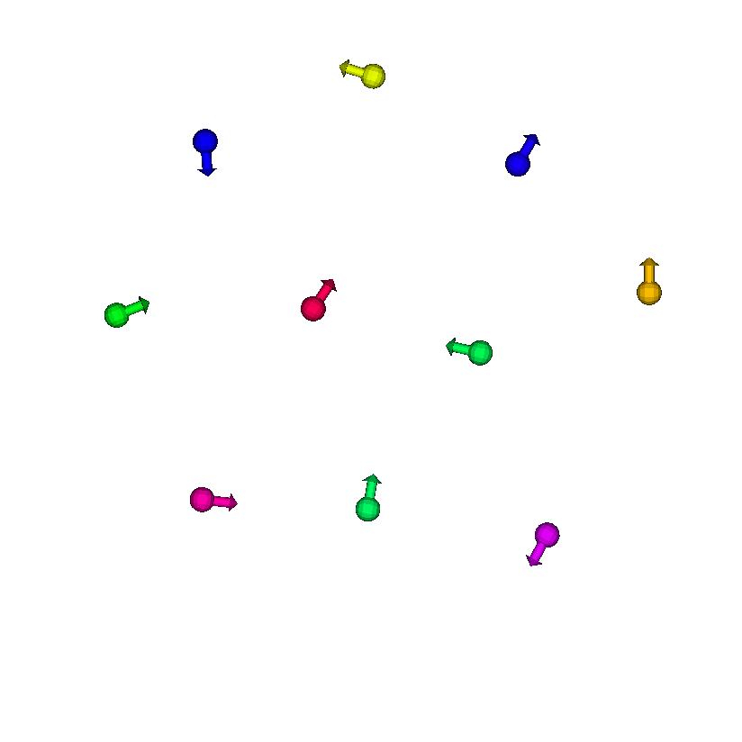
We now study the behaviour of swarmalatorbots via ROS 2 simulations and experiments with our robotic platform. After initial placement, each entity acts as a swarmalator and interacts with all other entities. As time progresses, each entity changes its state in terms of position , orientation and phase . After some time, a snapshot of the resulting pattern is taken. The orientation of an entity is visualised by an arrow and its phase by a colour. All tests are made with the natural frequency .
IV-A Simulation Results
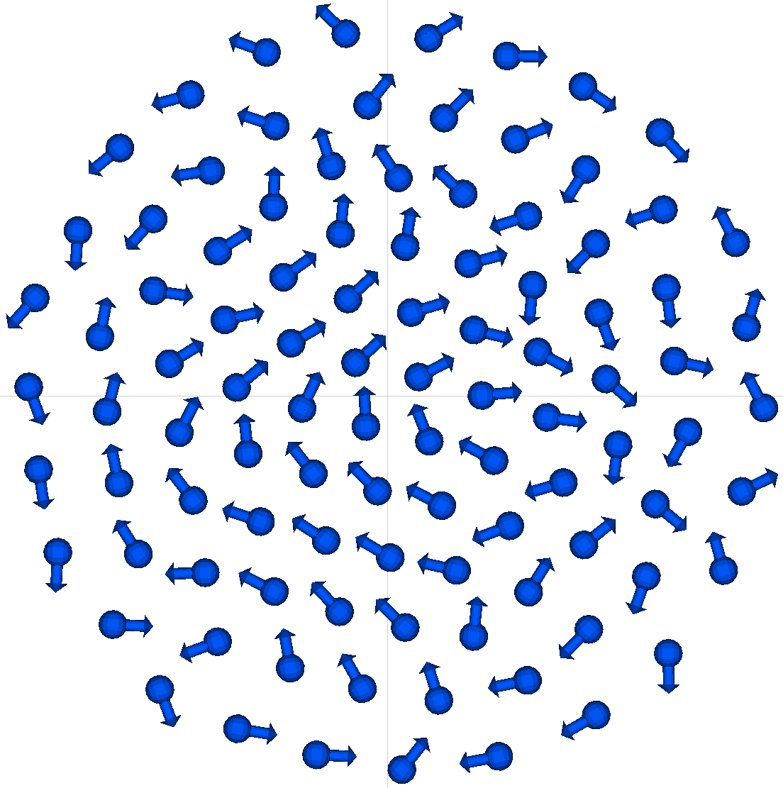
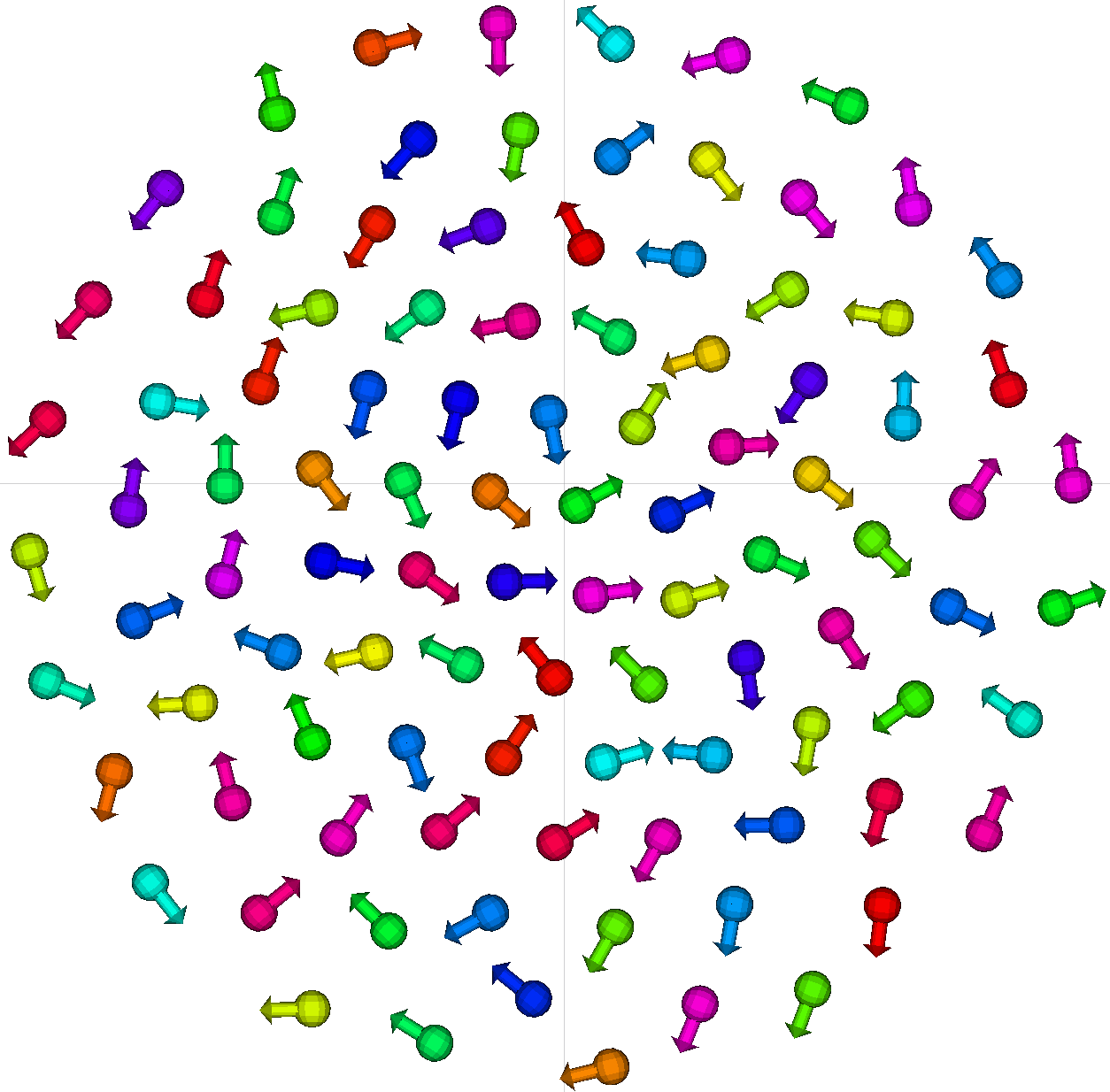
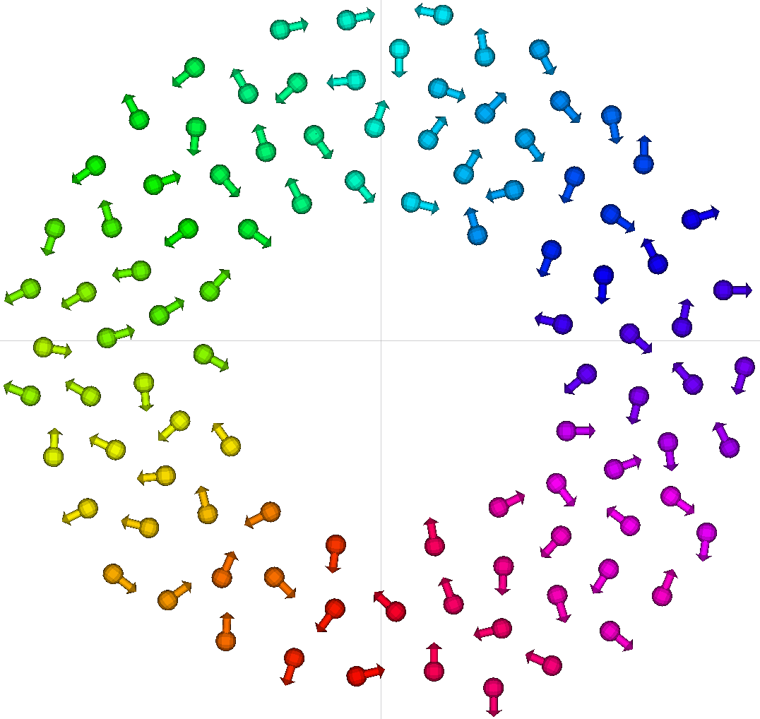
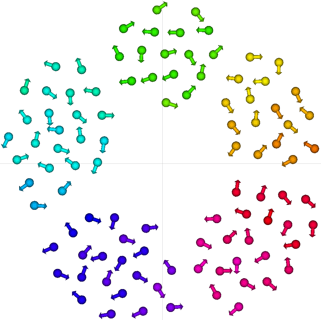
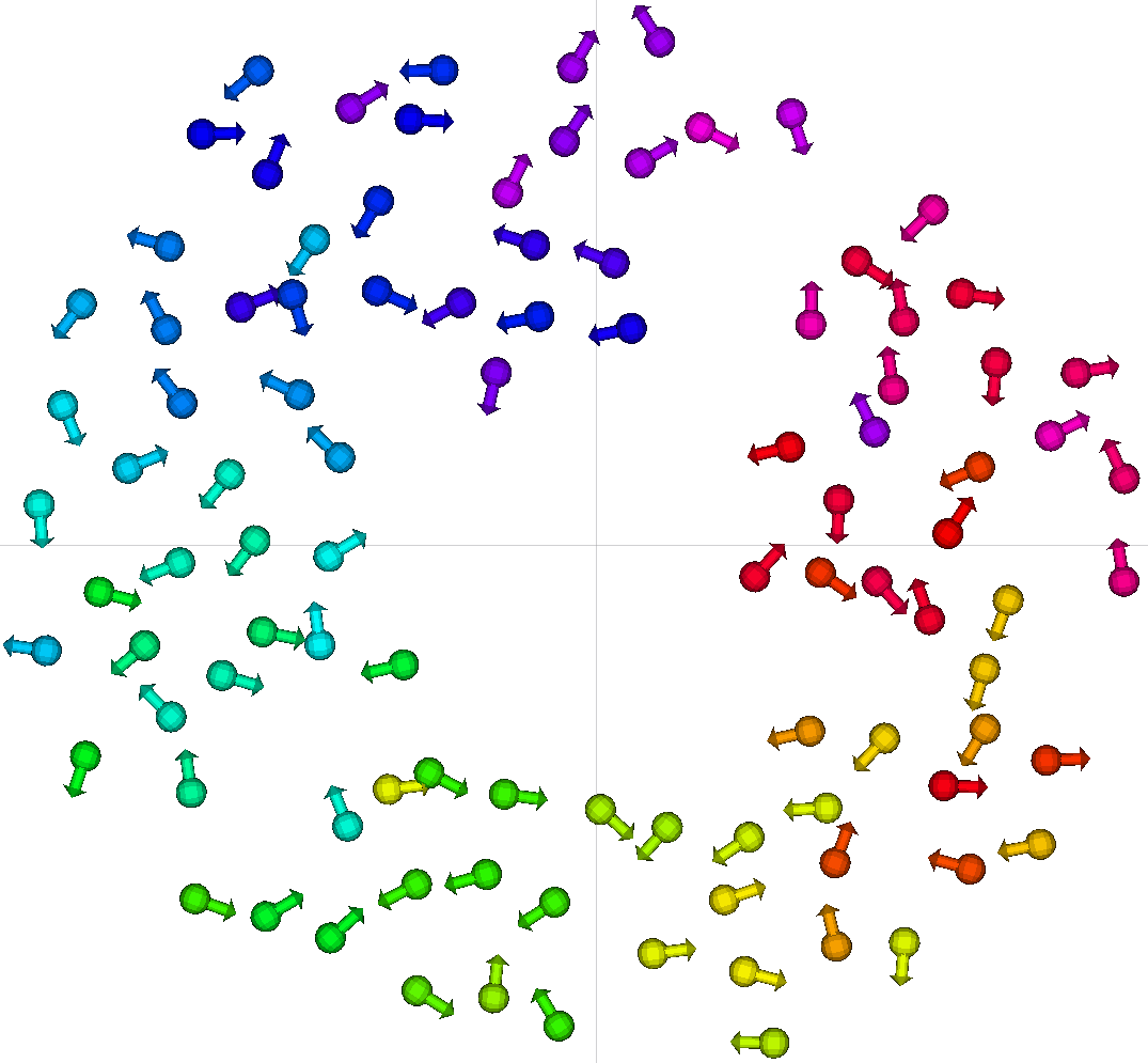
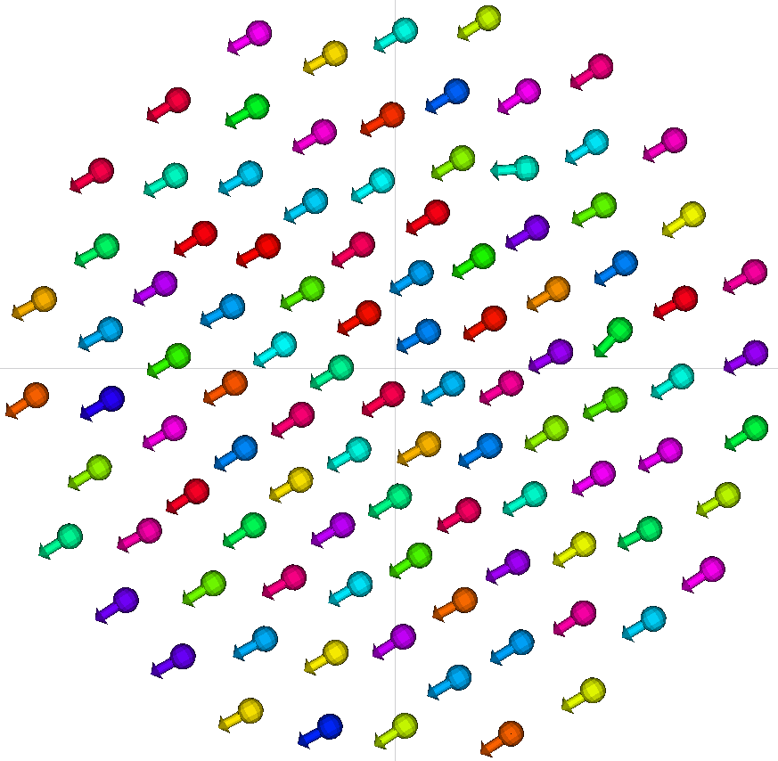
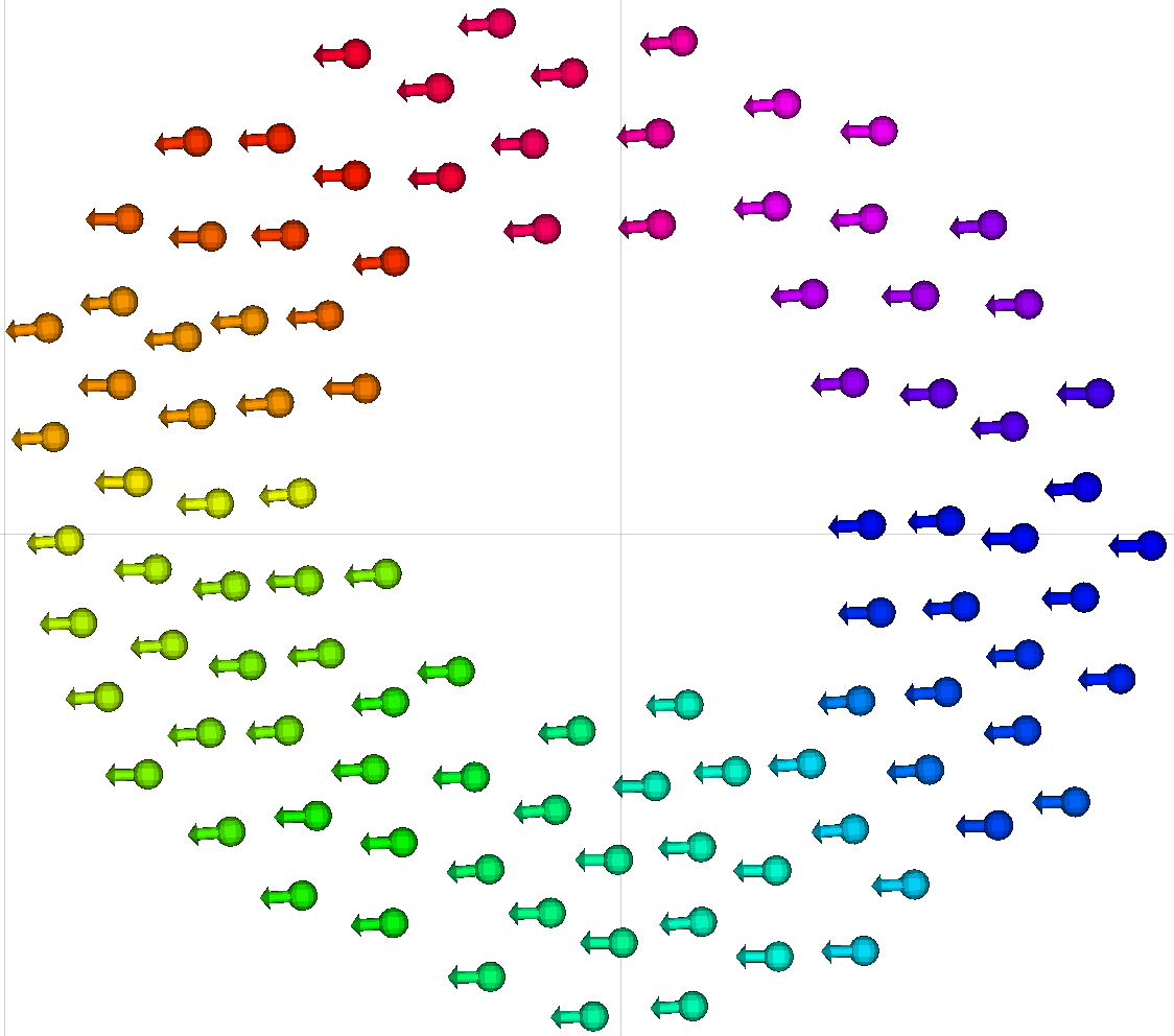
Simulations are conducted for entities, whose initial placement is sampled from a uniform random distribution in a square area with length units. As a first step, we simulate the original swarmalator model for mutual validation. All five patterns introduced in [5] are qualitatively reproduced. Next, we simulate the model suited for robots in order to check whether the modifications influence the capability to form patterns. Figure 1 shows some examples of patterns achieved without alignment of orientations (). We conclude that it is possible to obtain all the patterns in this robot model.
The parameter set yields a pattern with entities synchronised and regularly distributed inside a circle. The set gives a similar pattern but keeps the nodes in asynchrony. For , all entities are regularly distributed on a ring, where the ones with similar phases are close to each other. The last two states are non-stationary. For , the entities create disconnected clusters of similar phases around a ring and keep moving inside these clusters; this is called the splintered phase wave [5]. For , the entities move around the ring while their phases oscillate; this is called the active phase wave [5].
We observed that — even with static patterns — the swarmalatorbots are not fully stationary but that their positions slightly oscillate. This behaviour can occur due to the temporal discretisation of the model and because the simulation is distributed, i.e. the communication between entities is asynchronous and may suffer from message loss. These phenomena can lead to disturbances in the patterns.
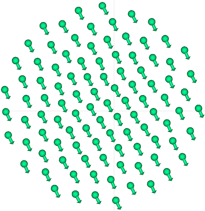
Some patterns also emerge if we include orientation alignment (). Figure 2 shows examples for the three static patterns. The two non-stationary patterns cannot, in general, be formed with our orientation alignment.
We observed that the introduction of movement constraints typically slows down the formation of the patterns. This also means that orientation alignment leads to even slower convergence. Once the pattern stabilizes, the variance in position is slightly higher with orientation alignment, as the correction of disturbances occurs slower.
IV-B Results with Robotic Prototype
| Robots | Visualisation | Trace: formed pattern | Trace: pattern forming | |
|---|---|---|---|---|
| Static sync |
|
|
|
|
| Aligned static sync |
|
|
|
|
| Static async |
|
|
|
|
| Aligned static async |
|
|
|

|
| Static phase wave |
|
|
|
|
| Aligned static phase wave |
|
|
|
|
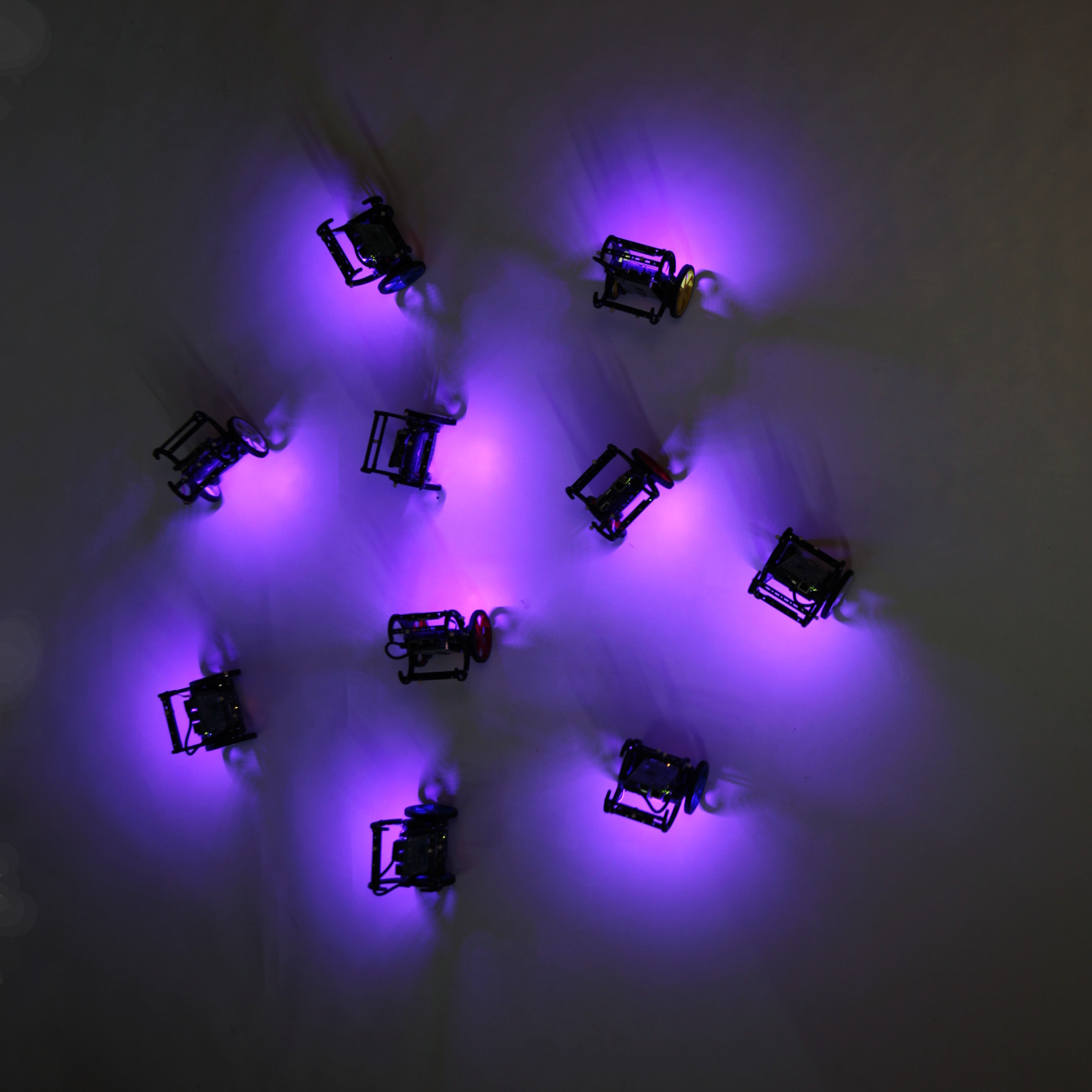
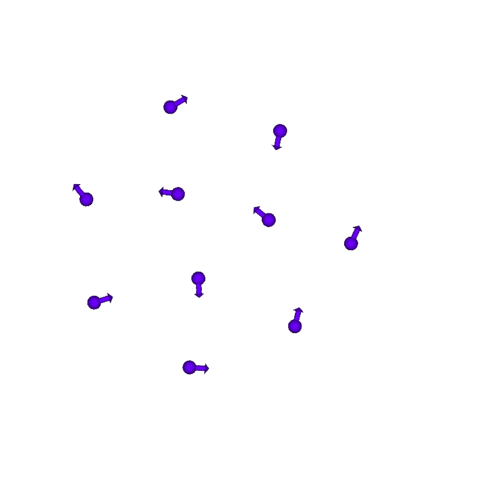
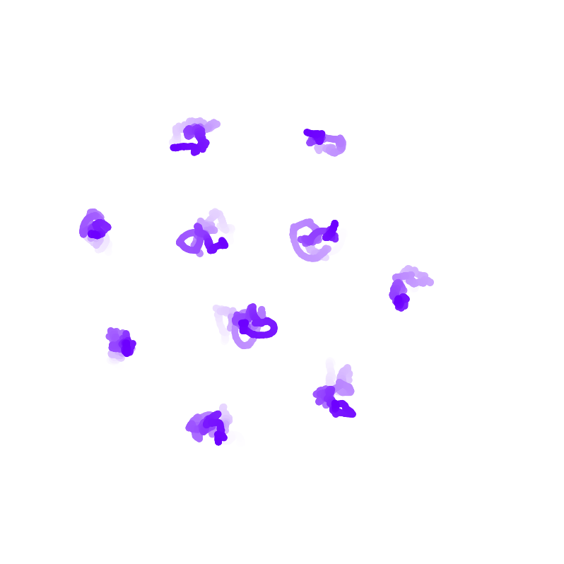
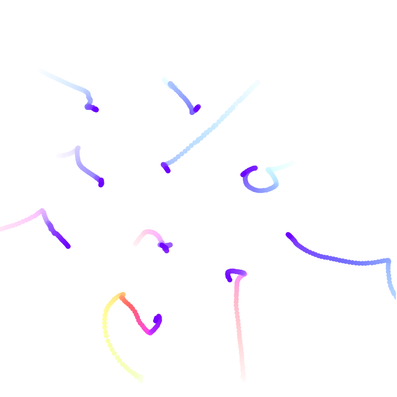
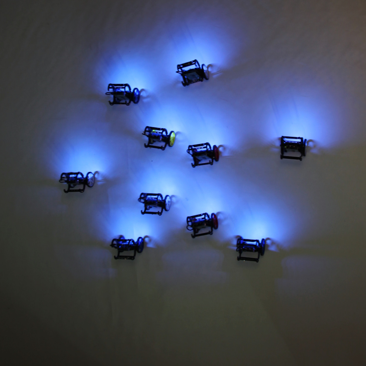
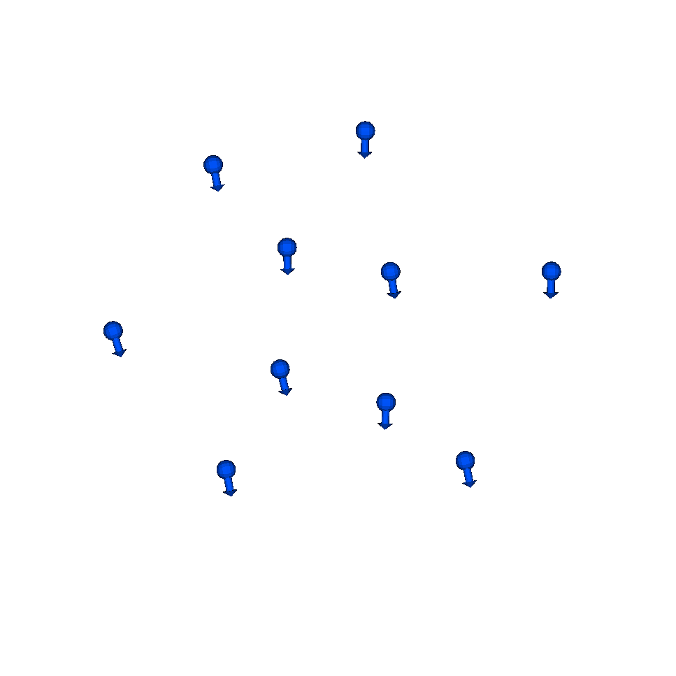
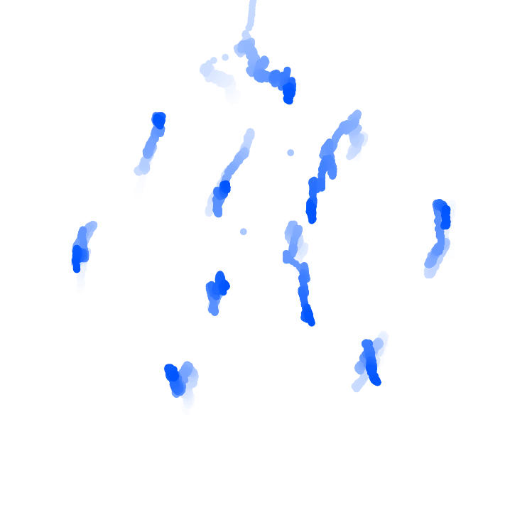
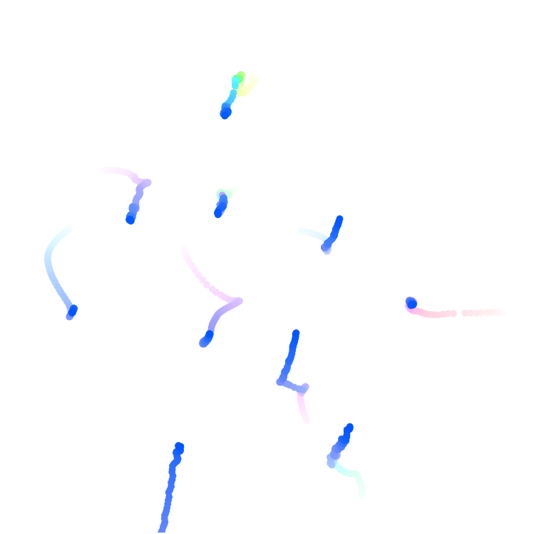
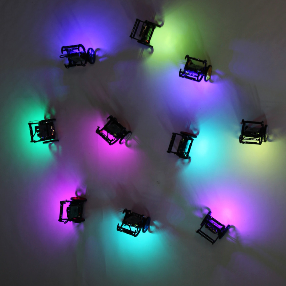
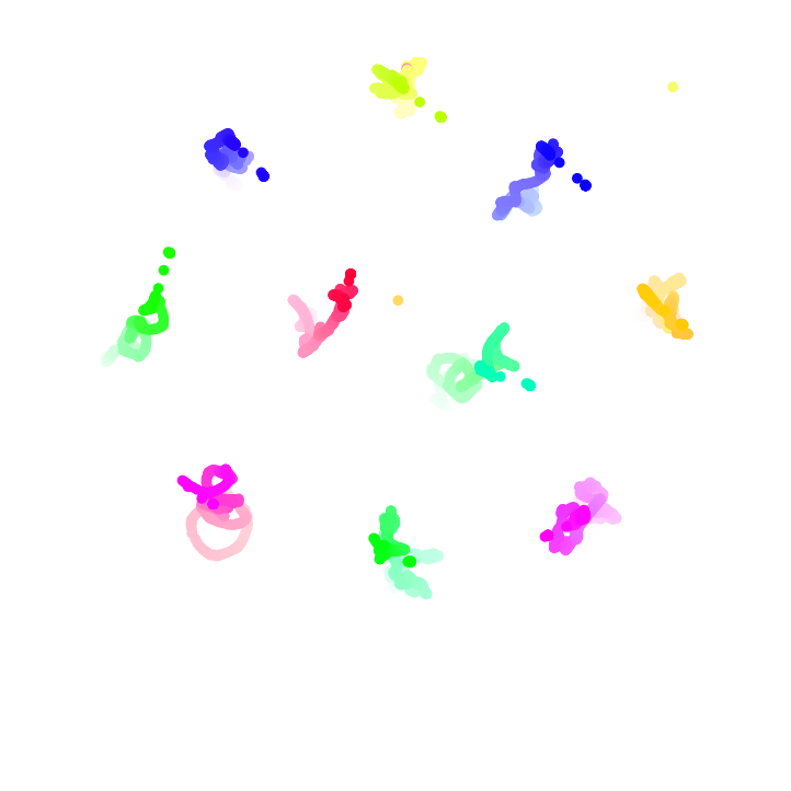
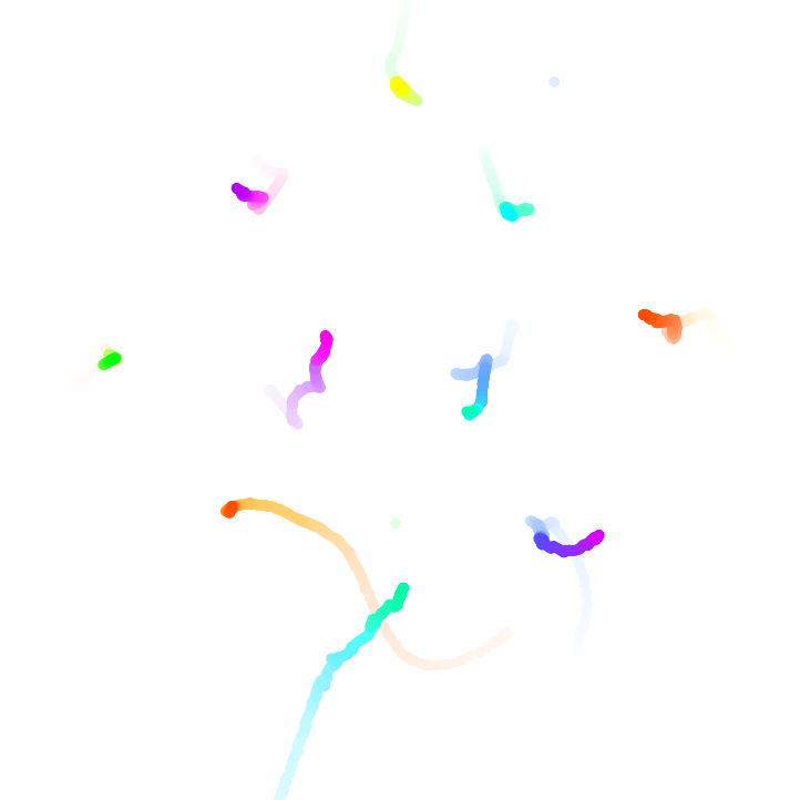
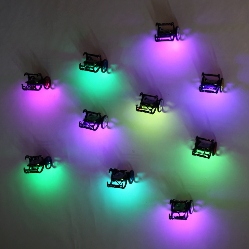
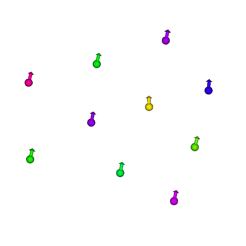
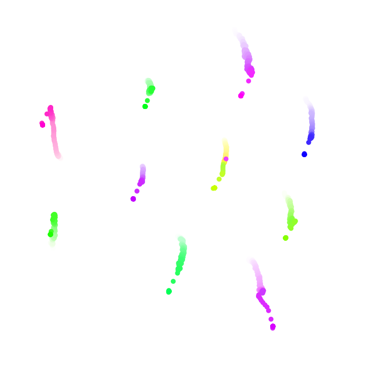
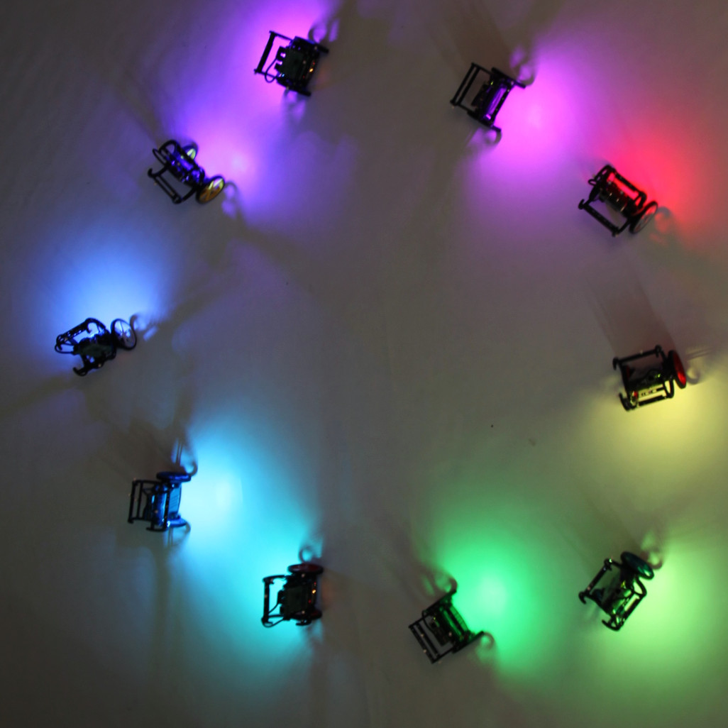
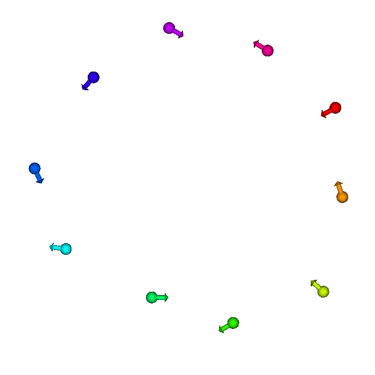
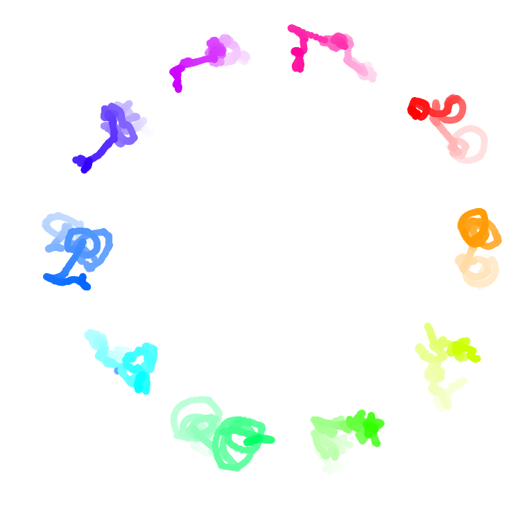
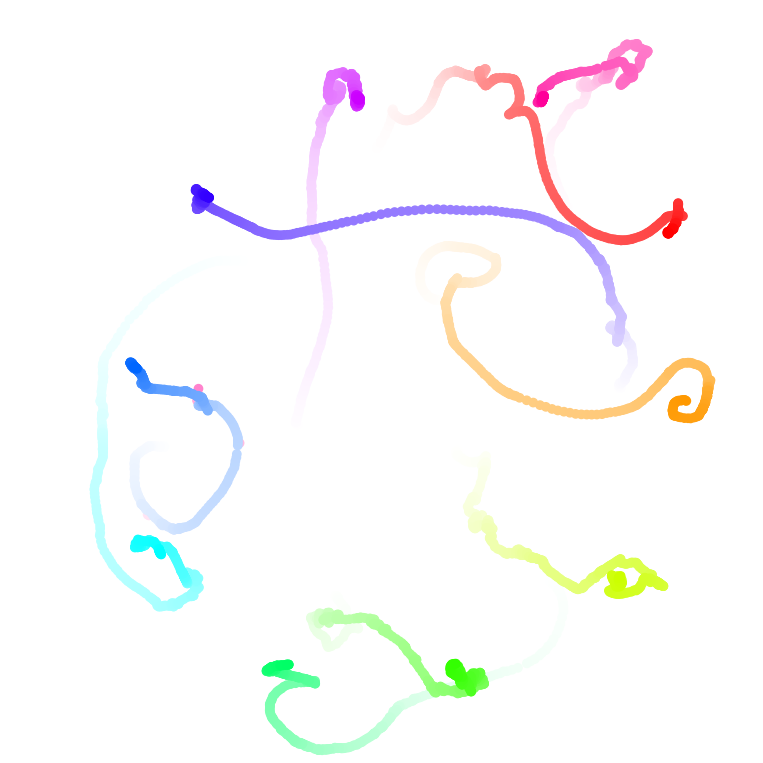
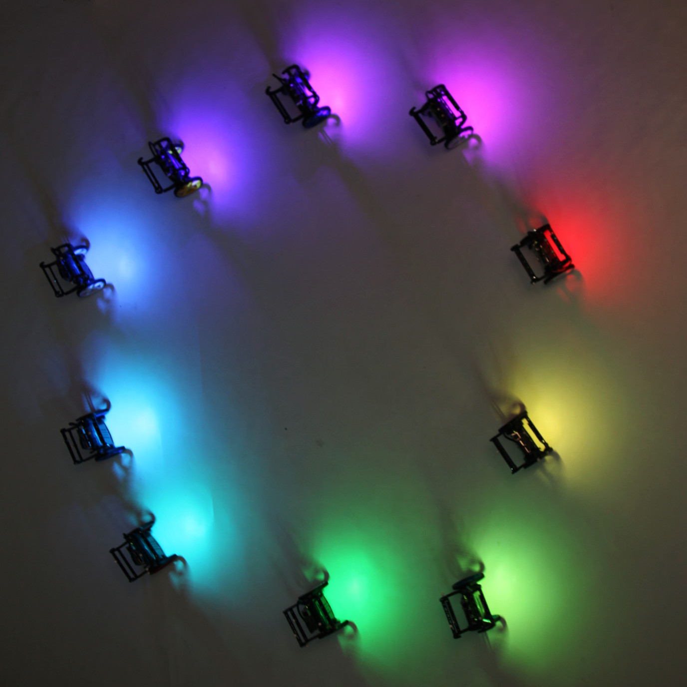
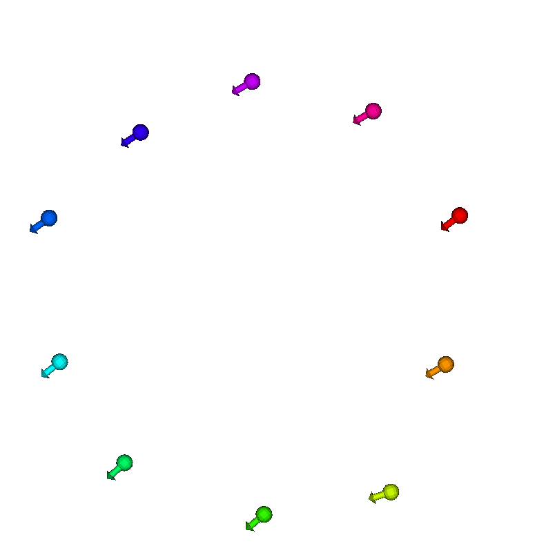
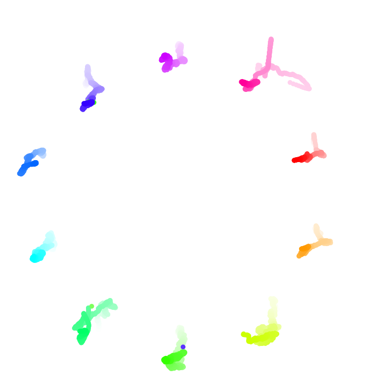
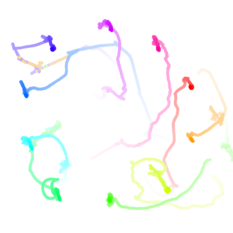
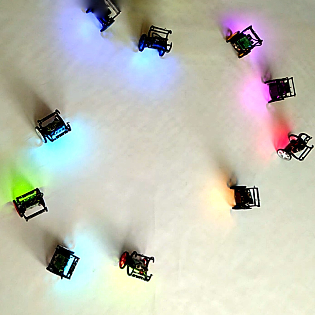
Experiments are made with robots running the model implemented in ROS 2. A video about our experiments can be seen on the website [16]. Example results are presented in Figures 3 and 4. All patterns except the splintered phase wave are reproduced. The splintered phase wave is not visible with our setup due to the low number of entities. For all stationary patterns (Figure 3), both versions with and without orientation alignment are created. Despite the low number of entities, the formed patterns are clearly visible and can be mapped to the different pattern types. Figure 3 contains four figures for each stationary state: the bird’s eye view of the robots forming the pattern (Robots), snapshot from the visualisation tool (Visualisation), trace with the formed pattern, showing that the state is stationary (Trace: formed pattern) and the trace of pattern forming (Trace: pattern forming). Older samples are visualised with a lighter colour. The active phase wave formed by robots is presented in Figure 4; the trace shows the robots’ movement after the pattern has formed.
Disturbances similar to the ones in the simulations can be observed with the real robots. They become even more visible in the experiments because of the variable communication characteristics as well as the robot’s inertia and imperfect state estimation.
V Related Work
There is a broad spectrum of scientific work on spatial and temporal coordination techniques that have been applied to multi-robot systems.
Publications on spatial coordination propose and evaluate methods for pattern formation and control [17, 18, 19], swarm navigation with obstacle avoidance [20], decentralised flocking [21, 22], and dependency of flocking on communication [23], to give some examples. All these approaches are without any interaction regarding temporal coordination.
Temporal coordination is often used in engineered systems but seldom coupled with spatial coordination. Algorithms in this domain suited for multi-robot systems are often inspired by phenomena of self-organising synchronisation in nature. Here, entities exchange simple pulses over radio [24, 25], sound [26], or light [27]. There are only a few approaches combining synchronisation and swarming. They use synchronisation for swarm coordination but do not couple them in a bidirectional way. Christensen et al. propose a method in which robots detect faulty agents because they have stopped blinking [28]. Hartbauer et al. describe how light emitted by robots can be used as a guiding signal [29].
VI Conclusions and Outlook
The swarmalator concept for coupled synchronisation and swarming has been realised and investigated for the first time in a real-world system. We have adapted and extended the original mathematical model for its use in mobile robotics and implemented it in ROS 2. Simulations and experiments with our Balboa-based platform serve as a proof of concept. The real-world demonstrations reveal some artefacts, e.g. the swarmalatorbots slightly oscillate around a given position, even with static patterns. Furthermore, we observed that the communication delay has a huge impact on the patterns stationarity if . For example, the static phase wave starts to rotate. This phenomenon requires further investigation.
Applications of swarmalatorbots are in fields with coordinated mobility of multiple entities, such as monitoring, exploration, entertainment and art. To realise these applications, our future work will use small drones creating three-dimensional swarmalator patterns in outdoor environments.
Acknowledgements
This work was supported by the Karl Popper Kolleg on Networked Autonomous Aerial Vehicles at the University of Klagenfurt and by the Austrian Science Fund (FWF) under grant P30012-NBL on self-organising synchronisation.
References
- [1] E. Bonabeau, M. Dorigo, and G. Theraulaz, Swarm Intelligence: From Natural to Artificial Systems. Oxford University Press, 1999.
- [2] S. Camazine, J.-L. Deneubourg, N. R. Franks, J. Sneyd, G. Theraula, and E. Bonabeau, Self-Organization in Biological Systems. Princeton University Press, Sep. 2003.
- [3] S. H. Strogatz, Sync: How Order Emerges From Chaos In the Universe, Nature, and Daily Life. Hachette Books, Apr. 2004.
- [4] H. Hamann, Swarm Robotics: A Formal Approach. Springer, 2018.
- [5] K. P. O’Keeffe, H. Hong, and S. H. Strogatz, “Oscillators that sync and swarm,” Nature Communications, vol. 8, no. 1, Nov. 2017.
- [6] “Pololu Balboa 32U4 Balancing Robot user’s guide,” https://www.pololu.com/docs/0J70.
- [7] K. P. O’Keeffe, J. H. M. Evers, and T. Kolokolnikov, “Ring states in swarmalator systems,” Physical Review E, vol. 98, no. 2, p. 022203, Aug. 2018.
- [8] H. Hong, “Active phase wave in the system of swarmalators with attractive phase coupling,” Chaos: An Interdisciplinary Journal of Nonlinear Science, vol. 28, no. 10, p. 103112, 2018.
- [9] M. Rubenstein, C. Ahler, and R. Nagpal, “Kilobot: A low cost scalable robot system for collective behaviors,” in Proc. IEEE Intern. Conf. on Robotics and Automation (ICRA), May 2012, pp. 3293–3298.
- [10] M. Jdeed, S. Zhevzhyk, F. Steinkellner, and W. Elmenreich, “Spiderino—A low-cost robot for swarm research and educational purposes,” in Proc. Workshop on Intelligent Solutions in Embedded Systems (WISES), Jun. 2017, pp. 35–39.
- [11] “Balboa low level controller source code,” https://gitlab.aau.at/aau-nav/development/balboa_llc_aws.
- [12] “OptiTrack - motion capture systems,” http://optitrack.com/.
- [13] J. Jun, P. Peddabachagari, and M. Sichitiu, “Theoretical maximum throughput of IEEE 802.11 and its applications,” in Proc. IEEE Intern. Symp. on Network Comput. and Applications, May 2003, pp. 249–256.
- [14] L. Hochstein and R. Moser, Ansible: Up and Running: Automating Configuration Management and Deployment the Easy Way. O’Reilly, Jul. 2017.
- [15] “Source code repository with Ansible playbooks,” https://gitlab.aau.at/aau-nav/development/ansible-playbooks.
- [16] “Video: Robots that sync and swarm: A proof of concept in ROS2,” https://bettstetter.com/swarmalatorbots/.
- [17] I. Suzuki and M. Yamashita, “Distributed anonymous mobile robots: Formation of geometric patterns,” SIAM Journal on Computing, vol. 28, no. 4, pp. 1347–1363, Jan. 1999.
- [18] H. C.-H. Hsu and A. Liu, “Multiagent-based multi-team formation control for mobile robots,” Journal of Intelligent and Robotic Systems, vol. 42, no. 4, pp. 337–360, Apr. 2005.
- [19] L. Barnes, M. Fields, and K. Valavanis, “Unmanned ground vehicle swarm formation control using potential fields,” in Proc. Mediterranean Conf. on Control Automation, Jun. 2007.
- [20] L. S. Junior and N. Nedjah, “Efficient strategy for collective navigation control in swarm robotics,” Procedia Computer Science, vol. 80, pp. 814–823, Jan. 2016.
- [21] A. E. Turgut, H. Çelikkanat, F. Gökçe, and E. Şahin, “Self-organized flocking in mobile robot swarms,” Swarm Intelligence, vol. 2, no. 2-4, pp. 97–120, Dec. 2008.
- [22] E. Ferrante, A. E. Turgut, C. Huepe, A. Stranieri, C. Pinciroli, and M. Dorigo, “Self-organized flocking with a mobile robot swarm: A novel motion control method,” Adaptive Behavior, vol. 20, no. 6, pp. 460–477, Dec. 2012.
- [23] S. Hauert, S. Leven, M. Varga, F. Ruini, A. Cangelosi, J. Zufferey, and D. Floreano, “Reynolds flocking in reality with fixed-wing robots: Communication range vs. maximum turning rate,” in Proc. IEEE/RSJ Intern. Conf. on Intelligent Robots and Systems, Sep. 2011, pp. 5015–5020.
- [24] G. Brandner, U. Schilcher, and C. Bettstetter, “Firefly synchronization with phase rate equalization and its experimental analysis in wireless systems,” Computer Networks, vol. 97, pp. 74–87, Mar. 2016.
- [25] Y.-W. Hong and A. Scaglione, “A scalable synchronization protocol for large scale sensor networks and its applications,” IEEE Journal on Selected Areas in Communications, vol. 23, no. 5, pp. 1085–1099, May 2005.
- [26] V. Trianni and S. Nolfi, “Self-organizing sync in a robotic swarm: A dynamical system view,” IEEE Transactions on Evolutionary Computation, vol. 13, no. 4, pp. 722–741, Aug. 2009.
- [27] F. Perez-Diaz, R. Zillmer, and R. Groß, “Firefly-inspired synchronization in swarms of mobile agents,” in Proc. Intern. Conf. on Autonom. Agents and Multiagent Syst., Richland, SC, 2015, pp. 279–286.
- [28] A. L. Christensen, R. O’Grady, and M. Dorigo, “From fireflies to fault-tolerant swarms of robots,” IEEE Transactions on Evolutionary Computation, vol. 13, no. 4, pp. 754–766, Aug. 2009.
- [29] M. Hartbauer and H. Römer, “A novel distributed swarm control strategy based on coupled signal oscillators,” Bioinspiration & Biomimetics, vol. 2, no. 3, pp. 42–55, 2007.