Super-directional light emission and emission reversal from micro cavity arrays
Abstract
Optical microdisk cavities with certain asymmetric shapes are known to possess unidirectional far-field emission properties. Here, we investigate arrays of these dielectric microresonators with respect to their emission properties resulting from the coherent behaviour of the coupled constituents. This approach is inspired by electronic mesoscopic physics where the additional interference effects are known to enhance the properties of the individual system. As an example we study the linear arrangement of nominally identical Limaçon-shaped cavities and find mostly an increase of the portion of directional emitted light while its angular spread is largely diminished from 20 degrees for the single cavity to about 3 degrees for a linear array of 10 Limaçon resonators, in fair agreement with a simple array model. Moreover, by varying the inter-cavity distance we observe windows of reversion of the emission directionality and super-directionality that can be interesting for applications. We introduce a generalized array factor model that takes the coupling into account.
pacs:
42.55.Sa, 42.60.Da,Introduction. Optical microdisk cavities have become a target of intense studies because of their versatile properties to control light, and their unique application potential Vahala (2003) as high-Q resonators Michael et al. (2007), microlasers McCall et al. (1992), Harayama and Shinohara (2011) or sensorsArmani et al. (2007), Xu et al. (2018). Moreover, they play an important role as widely accessible experimental realizations of theoretical model systems Cao and Wiersig (2015) used in quantum chaos St ckmann (1999); Nöckel and Stone (1997); Yang et al. (2010); Wiersig et al. (2011) and mesoscopic physics Datta (1995).
In view of the mutual inspiration of nonlinear dynamics, quantum chaos, antenna theory and the field of optical microcavities (a paradigm example being the intimate relation between the unstable manifold of the cavity and its far-field emission characteristics Lee et al. (2005); Wiersig and Hentschel (2008)), it is suggestive to take further inspiration from mesoscopic physics and its tool box. Besides the wide field of the manipulation of geometric phases Berry (1984); M. Nakahara (1990) in dielectric systems Bliokh et al. (2008); Ma et al. (2016); Kreismann and Hentschel (2018), extension of the single system into array or ensemble structures is known to enhance specific properties in electronic mesoscopic systems. For example, side structures of Aharonov-Bohm peaks in magnetoconductance oscillations were resolved in arrays of electronic micro-rings due to self-averaging in the composite system Nitta et al. (1999).
In the present work, we want to adopt the concept of arrays to optical microcavities. Our naive expectation and motivation is the possibility of an enhancement of directional emission properties inherent to single deformed optical microdisk cavities, e.g. of the Limaçon shape Wiersig and Hentschel (2008). To this end, we investigate a linear array (chain) of Limaçon resonators. The shape of each Limaçon resonator is given in two-dimensional polar coordinates by , where and represent the mean radius and the deformation parameter, respectively. The resonator itself is assumed to be purely dielectric with a high refractive index of embedded in vacuum, . The deformation parameter is set to , a value known Wiersig and Hentschel (2008) to provide highly directional far fields.
We use MEEP (MIT Electromagnetic Equation Propagation Oskooi et al. (2010)), a free finite-difference time-domain (FDTD) software package for electromagnetic wave simulations, to calculate the normalized resonance frequencies of the Limaçon resonator, with being the complex frequency and the speed of light, the quality factor , the distributions of the electric field component (modes) and the far-field intensity with far-field angle . In the present work, we study wavelength-scale cavities. For this reason, , with being the wave number and the wavelength in vacuum. We use -point-dipole sources (electric field perpendicular to the cavity) placed off-center to excite the same mode in each cavity and focus on TM-polarized modes.
In addition we use COMSOL Wave Optics Module User’s Guide (2018) in order to calculate the eigenfrequency splitting of the resonator array, which results from the exchange of energy among adjacent resonators.
We indeed observe the expected enhancement of the far-field emission of Limaçon arrays in comparison to the single resonator due to the coherent operation of all microcavities in the array. We describe this effect in the first part of the paper for the weak (evanescent) coupling regime.
However, under certain conditions we observe the opposite behaviour, i.e., a reversal of the main emission direction, or super-directional emission, as a result of the collective action. We investigate this strong-coupling regime in the second part of the paper and conclude with a summary.
We point out that the excitation scheme used in the MEEP simulations is such that
all resonators are excited equally (symmetric configuration, “even mode”) close to the eigenfrequency of the single cavity. Since the excitation pulse in each resonator has a finite spectral width that is slightly broader than the spectral splitting of the array modes for the not too small (and experimentally relevant) -values considered here, we observe an excitation close to the symmetric array mode with intensity distributions close to that of the single cavity, cf. Supplemental Material SEC. I SM , and dedicate the following discussion to this case.
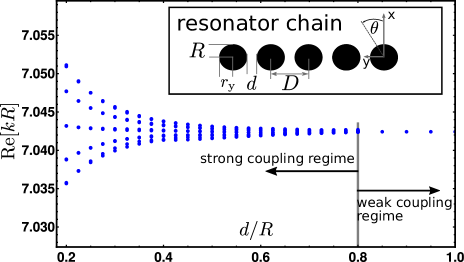
Array emission in the weak-coupling regime. We first investigate a row of Limaçon resonators with large inter-resonator distance . In this regime, the eigenfrequencies do not split, see FIG. 1, indicating that the resonators do not exchange energy. The entire array of resonators can thus be treated as a superposition of individual resonators:
| (1) |
where describes the electric (or magnetic) field distribution of the resonator array, and are the electric (or magnetic) eigenmodes of a single Limaçon resonator shifted along the y-axis by . The complex-valued coefficients represent the amplitude and phase of the -th resonator. In order to compute the far fields (fields in the Fraunhofer region) of the array, we use the near-field-to-far-field-transformation, a common method in FDTD Inan and Marshall (2011). From Eq. (1) follows the z-component of the electric far field (see Supplemental Material SEC. II SM ):
| (2) |
where is the z-component of the electric far field of a single resonator, and represents the far-field angle, see FIG 1. The sum on the right-hand side of the equation is also known as the array factor from antenna theory Balanis (2016). The array factor describes the complex-valued far-field pattern of a uniform linear array of point sources. Thus, the total far field results from that of a single resonator multiplied by the array factor. Indeed, our configuration is very similar to antenna arrays.
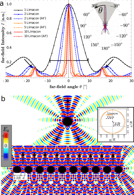
First, we wish to study the difference between the far fields of the single resonator and of an array. Figure 2 a shows the far-field intensity depending on the far-field angle within the range of degrees for 1, 2, 5 and 10 resonators aligned in a row with constant inter-resonator distance . The solid lines are the results from the full FDTD calculation whereas the dashed lines represent results assuming the array factor model according to Eq. (2). The inset presents the full polar plot of the far-field intensity. The gray region marks the degrees range.
The agreement between these results suggests that the resonator array behaves as expected from an antenna array in the weak-coupling regime considered here 111The coefficients have been all set to unity because there is no mutual coupling between the resonators, and all resonators have been excited equally.. As a result, the width of the main lobe decreases with increasing number of array elements (resonators) yielding increased directivity. This feature conforms quantitatively to the array factor model. Specifically, we observe that the width of the main lobe of the far-field emission from 10 Limaçon resonators is reduced by roughly one order of magnitude compared to the single resonator case. Furthermore, we observe that the position and height of the side lobes varies with the number of elements, saturation at (cf. the black arrows). This behaviour results from the array factor as well (see Supplemental Material FIG. 2 SM for more details).
Figure 2 b displays the normalized -field distribution
for one and 10 Limaçon resonators, respectively.
The far field of one Limaçon resonator (upper panel) is well known and very similar to the results e.g. in Song et al. (2011). The lower panel shows the situation for
10 resonators and reveals a strong emission in forward direction as indicated by the black arrows. This enhancement arises from the superposition of individual, unperturbed resonator modes of the single Limaçon cavity within the array.
Array emission in the strong-coupling regime. We now investigate the emission of the resonator array for intercavity distances smaller than 1, i.e. encountering (strong) element coupling. Here, the resonators are close enough to exchange energy by mutual coupling. As a result, the frequencies of the single resonators split, and array modes emerge, see FIG. 1 and Supplemental Material FIG. 1 SM . Naturally, the array factor model, Eq. (1, 2), remains no longer valid. Due to the coupling, the properties of coupled cavities differ from the isolated case. However, a generalization of this model (generalized array factor model) takes the coupling of the resonators into account by replacing and of the bare single cavity with the respective quantities and of the single coupled cavity. The far field of the resonator array in the strong coupling regime is modeled by multiplying the far fields of the single coupled cavity with the array factor:
| (3) |
The generalized array factor model can qualitatively predict the observed array far fields with all features described below while emphasizing the role of coupling.
In order to quantify the directional emission of a resonator array, we introduce the far-field emission ratio that is defined by:
| (4) |
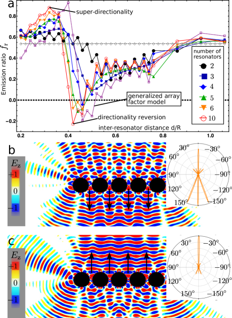
where is the forward directional emission and represents the backward directional emission. Emission ratios greater (smaller) than represent forward (backward) directionality, whereas values around indicate balanced forward and backward emission. By means of the ratio , we study the far-field behaviour of the resonator array as a function of the inter-resonator distance which is displayed in Figure 3 a.
Reversal of emission directionality. According to FIG. 3 a we observe that decreasing
and hence increasing the coupling strength, reduces the emission ratio , i.e., less light is emitted into the forward direction. For arrays consisting of more than three resonators, we find the emission ratio to change sign, indicating backward emission and thus a reversal of the emission directionality. For the mode chosen and resonators, we find to reach a minimum of around at a cavity spacing of .
The purple dashed line shows the result of a 10-resonator array obtained with the generalized array factor model ( has been taken from a 4-resonator array) which nicely agrees with the results from the full FDTD calculation.
In order to investigate this behavior in more detail, we look at the spatial distribution of the -component of the electric field amplitude as depicted in FIG. 3 b.
We clearly see a wave propagating downwards below the resonator array (resembling a plane wave propagation) as indicated by the black arrows. Above the resonator row, we observe wave propagation in form of an interference pattern that indicates partially destructive interference. The inset displays the entire far-field emission as a polar plot, and confirms that more energy is emitted backwards than forwards.
Assuming coupling between the resonators to be the reason for the directionality reversion, then an interesting question is: Why do 5 resonators show reversion, but 2 resonators do not?
Following the -curve of 2 resonators in FIG. 3 a, we observe that the emission ratio decreases a bit with decreasing -values but its minimum remains positive. This slight decrease of indicates an increase of the energy emitted into the backwards direction. It turns out that directionality reversion is already present for 2 resonators but it is masked by the emission from the edges of the array (see Supplemental Material FIG. 4 SM ). The directionality reversion arises from the coupling regions (in-between space of two resonators) and it needs a certain number of these coupling regions to overcome the effect of the emission from the edge regions.
Super-directional light emission from linear arrays.
By decreasing the distance between the resonators further, the emission ratio changes sign and reaches a maximum at for resonators. This maximum is even higher than the value found at the element distance . It indicates that the coherent modal action of the resonator array results in a super-directional forward emission of light. This is illustrated in Figure 3 c.
Contrary to Figure 3 b, we now find (almost) planar wave propagation into the forward direction. The interference pattern visible below the resonator row indicates destructive interference and hence reduced energy flow into the backward direction, as confirmed by the inset showing the full polar plot.
We point out that the emission patterns in Figs. 2 b and 3 c look similar as both correspond to values . Notice however that the planar-wave-type propagation (destructive interference) in forward (backward) direction are even more pronounced for the strong coupling case shown in Fig. 3 c.
The gray dashed line in FIG. 3 a corresponds to the (standard) array factor model (Equ. 2) with resonators. It represents the case of weakly coupled resonators and shows a constant -value because of and being independent from .
Generalized array factor model.
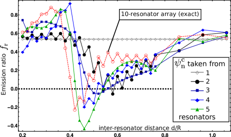
We now study the generalized array factor model in more detail. In this context, an interesting question is: Is it possible to predict the features of a 10-resonator array with the aid of the generalized array factor model utilizing the coupling features of a 2 or 3-resonator array?
To this end, we compute the emission ratio for a 10-resonator array based on the far fields obtained from the generalized array factor model where the have been taken
from a 1, 2, 3, 4, and 5 element resonator array, respectively (see Supplemental Material FIG. 3 SM ). The corresponding results are shown in FIG. 4 with a comparison to the exact emission ratio of a 10-resonator array. The case of taken from 1 resonator is identical to the array factor model of uncoupled resonators, as described by Equ. (2).
The emission ratio with taken from 2 resonators displays very weak directionality reversion and very weak super-directionality. At least, one could guess that such features exist. As pointed out earlier, the directionality reversion feature is already present for 2 resonators but it is masked by the emission from the edge regions.
The best agreement with the exact curve is obtained for the case with taken from 4 resonators.
Interestingly, the results with taken from 5 resonators
show too much directionality reversion compared to the exact result. The reason for this is that we neglected the role of the amplitudes . For reasons of simplicity, the have been set to unity which is not correct if the array gets larger, because of the amplitude distribution within the array mode with high amplitudes for central resonators and low amplitudes for edge resonators.
The generalized array factor model can qualitatively predict the emission ratio of a 10-resonator array and reveals that the reversion of the directionality arises from the coupling of the single resonator modes. It cannot be modeled by a proper superposition of the single resonator modes (as described in equation 2). Thus, the coupling between the resonators plays an essential role. This implies immediately that the reversed and super-directional emission will be resonance dependent, see Supplemental Material FIG. 5 SM . A complementary interpretation of our findings based on (generalized) phase-space arguments Wiersig and Hentschel (2008) is in progress and will be subject of a subsequent study.
Conclusion.
Our FDTD calculations revealed that the directionality of the emission of photonic devices can be considerably enhanced using array structures, both concerning the fraction of the directionally emitted light and its angular spread. Moreover, the main emission direction of the cavity ensemble can be inverted such that light is mostly emitted into the direction opposite the one of the singly cavity. We argue that this effect arises from the coupling of the individual resonators. The directionality properties depend strongly on (i) the normalized distance between the resonators and (ii) the properties of the individual resonant modes. Furthermore, the directionality reversion behavior depends on the number of the resonators in the array, and emerges only if their number is larger than three.
Acknowledgements.
This work was partly supported by Emmy-Noether programme of the German Research Foundation (DFG). Furhtermore, we thank Christoph Wagner from the Department of Advanced Electromagnetics for fruitful discussions.References
- Vahala (2003) K. J. Vahala, Nature 424, 839 (2003).
- Michael et al. (2007) C. P. Michael, K. Srinivasan, T. J. Johnson, O. Painter, K. H. Lee, K. Hennessy, H. Kim, and E. Hu, Appl. Phys. Lett. 90, (2007).
- McCall et al. (1992) S. L. McCall, A. F. J. Levi, R. E. Slusher, S. J. Pearton, and R. A. Logan, Appl. Phys. Lett. 60, 289 (1992).
- Harayama and Shinohara (2011) T. Harayama and S. Shinohara, Laser & Photonics Reviews 5, 247 (2011).
- Armani et al. (2007) A. M. Armani, R. P. Kulkarni, S. E. Fraser, R. C. Flagan, and K. J. Vahala, Science 317, 783 (2007).
- Xu et al. (2018) X. Xu, W. Chen, G. Zhao, Y. Li, C. Lu, and L. Yang, Light: Science & Applications 7, 62 (2018).
- Cao and Wiersig (2015) H. Cao and J. Wiersig, Rev. Mod. Phys. 87, 61 (2015).
- St ckmann (1999) H.-J. St ckmann, Quantum Chaos (Cambridge University Press, Cambridge, 1999).
- Nöckel and Stone (1997) J. U. Nöckel and A. D. Stone, Nature 385, 45 (1997).
- Yang et al. (2010) J. Yang, S.-B. Lee, S. Moon, S.-Y. Lee, S. W. Kim, T. T. A. Dao, J.-H. Lee, and K. An, Physical Review Letters 104, 243601 (2010).
- Wiersig et al. (2011) J. Wiersig, A. Eberspächer, J.-B. Shim, J.-W. Ryu, S. Shinohara, M. Hentschel, and H. Schomerus, Physical Review A 84, 23845 (2011).
- Datta (1995) S. Datta, Physics Today (Cambridge University Press, Cambridge, 1995) arXiv:0607219 [cond-mat] .
- Lee et al. (2005) S.-Y. Lee, J.-W. Ryu, T.-Y. Kwon, S. Rim, and C.-M. Kim, Physical Review A 72, 61801 (2005).
- Wiersig and Hentschel (2008) J. Wiersig and M. Hentschel, Physical Review Letters 100, 1 (2008), arXiv:0709.1770 .
- Berry (1984) M. V. Berry, Proceedings of the Royal Society of London A: Mathematical, Physical and Engineering Sciences 392, 45 (1984).
- M. Nakahara (1990) M. Nakahara, Geometry, Topology, and Physics (Bristol: IOP Publishing Ltd, 1990).
- Bliokh et al. (2008) K. Y. Bliokh, A. Niv, V. Kleiner, and E. Hasman, Nature Photonics 2, 748 (2008), arXiv:0810.2136 .
- Ma et al. (2016) L. B. Ma, S. L. Li, V. M. Fomin, M. Hentschel, J. B. Götte, Y. Yin, M. R. Jorgensen, and O. G. Schmidt, Nature Communications 7, 4 (2016).
- Kreismann and Hentschel (2018) J. Kreismann and M. Hentschel, EPL (Europhysics Letters) 121, 24001 (2018).
- Nitta et al. (1999) J. Nitta, H. Takayanagi, and S. Calvet, Microelectronic Engineering 47, 85 (1999).
- Oskooi et al. (2010) A. F. Oskooi, D. Roundy, M. Ibanescu, P. Bermel, J. D. Joannopoulos, and S. G. Johnson, Computer Physics Communications 181, 687 (2010).
- Wave Optics Module User’s Guide (2018) Wave Optics Module User’s Guide, “COMSOL Multiphysics® v. 5.4. COMSOL AB,” (2018).
- (23) See Supplemental Material at [URL] .
- Inan and Marshall (2011) U. S. Inan and R. A. Marshall, Numerical Electromagnetics (Cambridge University Press, Cambridge, 2011).
- Balanis (2016) C. A. Balanis, Antenna Theory: Analysis and Design, 4th ed. (Wiley, New York, 2016) p. 1104.
- Note (1) The coefficients have been all set to unity because there is no mutual coupling between the resonators, and all resonators have been excited equally.
- Song et al. (2011) Q. H. Song, L. Ge, J. Wiersig, J. B. Shim, J. Unterhinninghofen, A. Eberspächer, W. Fang, G. S. Solomon, and H. Cao, Physical Review A - Atomic, Molecular, and Optical Physics 84 (2011), 10.1103/PhysRevA.84.063843.