Radiation dominated implosion with flat target
Abstract
Abstract: Inertial Confinement Fusion is a promising option to provide massive, clean, and affordable energy for humanity in the future. The present status of research and development is hindered by hydrodynamic instabilities occurring at the intense compression of the target fuel by energetic laser beams. A recent proposal by Csernai et al. Csernai et al., (2018) combines advances in two fields: detonations in relativistic fluid dynamics and radiative energy deposition by plasmonic nano-shells. The initial compression of the target pellet can be eliminated or decreased, not to reach instabilities. A final and more energetic, short laser pulse can achieve rapid volume ignition, which should be as short as the penetration time of the light across the target. In the present study, we discuss a flat fuel target irradiated from both sides simultaneously. Here we propose an ignition energy with smaller compression, largely increased entropy and temperature increase, and instead of external indirect heating and huge energy loss, a maximized internal heating in the target with the help of recent advances in nano-technology. The reflectivity of the target can be made negligible, and the absorptivity can be increased by one or two orders of magnitude by plasmonic nano-shells embedded in the target fuel. Thus, higher ignition temperature and radiation dominated dynamics can be achieved. Here most of the interior will reach the ignition temperature simultaneously based on the results of relativistic fluid dynamics. This makes the development of any kind of instability impossible, which up to now prevented the complete ignition of the target.
pacs:
28.52.Av, 52.57.-z, 52.27.Ny, 52.35.Tc, 52.38.DxI Introduction
Inertial Confinement Fusion (ICF) is an ongoing activity aiming for ignition of small pellets of thermonuclear, deuterium-tritium (DT) fuel by high-power lasers. The main direction of activity aims for strong compression of the fuel, where the resulting adiabatic heating would ignite the fuel in a central hot spot. The pulse and the compression should be large and strong enough to keep the compressed fuel together for sufficient time for burning after ignition, due to the inertia of the compressed pellet. This is the aim of both the direct drive and indirect drive experiments.
In the present paper we work out the earlier presented idea Csernai et al., (2018, 2017) how to achieve nearly simultaneous volume ignition in the majority of the target. The two fundamentally new ideas in this work are the same, and to the benefit of the reader, to be able to read the article continuously, we repeat these principle items also here. However, now we also present the theoretical concept for a simplified, easier accessible, and energetically more advantageous flat target configuration. This obviously reduces the possibility to reach extreme compression, but our aim is to increase the target energy density, and for this purpose the flat target configuration is advantageous.
In the pellet the fusion reaction, , takes place at a temperature of keV. The produced (or ) particles are then deposited in the hot DT plasma and heat it further. This is the plasma self-heating (or -heating). The compression wave penetrates into the plasma with the speed of sound or with the speed of a slightly faster compression shock.
The goal of these experiments is to generate and sustain a self-propagating burn wave, which reaches the whole interior of the pellet. The present most advanced ICF experiments are done at the NIF, with spherical, , irradiation. Here we propose experiments simpler and more accessible for laboratories, than the spherical irradiation setups at NIF, (192 laser beams) Landen et al., (2012); Robey et al., (2012) or OMEGA, (80 laser beams) Nora et al., (2015). In the NIF experiments, the goal is to achieve extreme compression, and adiabatic heating. This results in extreme pressure, minimal entropy production, and the relatively smallest temperature increase. The extreme pressure leads to rapid subsequent expansion and to possible instabilities.
In the present paper we demonstrate the advantages of a method of short ignition pulse with plasmonic nano shells, for this configuration, with or without possible target pre-compression. The basis of the pre-compression is that the rate of fusion reactions in homogeneous medium is proportional to
| (1) |
where and are densities of D and T nuclei, is the reaction cross section and is the relative velocity. In the proposed rapid, linear ignition the relative velocity is not the thermal velocity, but the higher relative velocity of the two opposite beams!
The effect of higher density is also useful, as we will discuss it later.
Below, we suggest testing of the method with two laser beams pointing against each other with simultaneous irradiation pulses from both sides of the target. Such a configuration was tested recently successfully Zhang et al., (2019), however without two fundamentally new aspects, the nearly simultaneous heating to ignition on a so called time-like hypersurface, with a final short energetic laser pulse and embedded nano-antennas in the target to modify light absorption to achieve nearly uniform heating in the whole target volume.
We think that a realistic calculation may be made only by relativistic fluid dynamics (RFD). These velocities are significantly less than the speed of light, , so why would we need relativistic fluid dynamics to describe these reactions? RFD must be used not only with high velocities or high velocity gradients, but also for radiation dominated processes i.e. at high temperatures, when the energy density and the pressure are of the same order of magnitude and not dominated by the rest mass of the matter. RFD has qualitatively different features, proven theoretically and experimentally. In particular, detonation or burning fronts can be both space-like and time-like (i.e. simultaneous in space-time) Csernai, (1987). Also in radiation dominated processes, fluctuations of the burning front are smoothed out because radiation will transfer energy to volume elements with smaller energy density, which are created by mechanical flow fluctuations Zeldovich & Raiser, (1966).
Linear laser irradiation will increase the density of transparent target, as pointed out in case of ultra-relativistic heavy ions Gyulassy & Csernai, (1986), and also indicated by ref. Zhang et al., (2019). This mechanism is different from the ablator technique used in spherical geometry, and suppresses RT instability. Furthermore, the linear geometry leads to a non-isotropic momentum distribution where the accelerated ions are primarily moving in the beam direction like in colliding beam accelerators. Thus we avoid using the term temperature, and the term heating referes to the increase of the typical energy density but not to a thermalized isotropic momentum distribution, therefore we can use eq. (1) for the reaction rate.
II Considerations for the target
In the following we perform semi-analytic calculations disregarding the target’s compression. Here we consider a simple target configuration, without ablator using the early examples in refs. Csernai, (1987); Csernai & Strottman, (2015); Csernai et al., (2017). These estimates were based on analytic, scaling solution of relativistic radiation dominated fluid dynamics. For simplicity we consider flat solid targets to get quantitative estimates. We choose targets of 0.1-0.2 mm thickness, with deuterium-tritium (DT) ice and polylactic acid (PLA) or cyclic olefin copolymers (COC) as target materials. These latter two target materials serve to test the two fundamentally new ideas of this work
These targets have relatively small absorptivity. To absorb the whole energy of the incoming laser light on 0.1 mm length, we need an absorptivity of the order of cm-1. This is typical absorptivity of DT fuel for soft X-ray radiation of 1 nm wavelength, see Fig. 2 of ref. Hu et al., (2014). For softer radiation one gets larger absorptivity, and the radiation can be absorbed in the outer layers of the pellet.
As mentioned above we assume two counter propagating laser beams aiming at the target from both sides simultaneously.
III Simplified model for flat target
Let us consider a flat piece of matter, which is sufficiently transparent for radiation. The absorptivity of the target matter is considered to be constant, such that the total energy of the incoming light is absorbed fully when the light reaches the opposite edge of the flat target. This matter undergoes an exothermic reaction if its energy density that can be characterized by a temperature parameter exceeds . In a colliding beam configuration the collision rate exceeds the one in thermalized matter.
The target matter is irradiated by two laser beams simultaneously from the two opposite sides. For simplicity of the presentation, we are neglecting the matter expansion, so that the target thickness is taken to be constant. Experiment Zhang et al., (2019) indicates that this is an acceptable assumption.
The laser beam profile is assumed to be uniform over the surface
of the target. This requires adequate optical properties, which
may be critical for short,
(fs or ps)
pulses of high pulse energy and for a
0.01 mm2
target surface. For the lower energy test experiments and
material technology studies, a
1 mm2 flat target
surface size is sufficient.
Below we consider a coin-shaped target with , where
| (2) |
The laser irradiation comes from the directions while the side surface of the coin allows the laser light and particles to escape. This can be minimized by an external cover on the outside cylindrical edges made of a well reflecting material (like depleted Uranium-238) or with a metal of high melting point (like Tungsten).
In this ICF configuration the energy deposition will depend
on the coordinate.
The simultaneous ignition can be achieved if
the nano-shell concentration at the middle layer of the DT target
increases faster than in the spherical configuration.
We consider two options:
(A) Verification of the method of short (ps) ignition
with plasmonic nano shells, with a full volume transition
or melting of a non-explosive target material.
(B) Simultaneous fusion with smaller amount of
DT-ice target.
In both cases, the available laser pulse energy determines the possible outcome and the target size, which then provides us with the required ignition pulse length.
(A) Let us first consider option A. To test the basic principle of the method, we can study a phase transition of a transparent material the cyclic olefin copolymers, (COC) or the polylactic acid (PLA). We need transparent target for the penetration of the laser light. Let us take for example, the PLA. Its density is 1.21-1.43 g/cm3, melting point 150-160 ∘C, melting enthalpy 28-38 J/g. Note that a 30 mJ laser pulse could melt 1.07 mg of PLA. This amount of PLA has 0.82 mm3 volume. For a laser beam with 0.81 mm2 cross section the target thickness should be 1.02 mm to achieve melting of the considered target with one single pulse.
In this case the penetration time of the laser pulse through the target is 5.1 ps. considering a refractive index of 1.5. To achieve homogeneous melting the target should be doped with resonant golden nano-shells, with enhanced concentration in the middle. Our calculation shows (see below) that light absorption should be less on the flat target surface and more in the middle. By varying the pulse length while keeping the pulse energy constant, one can see earlier melting at the outside edges (for shorter pulse length) or at the center (for longer pulse length).
For example the Ti-Sapphire HIDRA laser with 30mJ pulse energy at Wigner RCP Aladi et al., (2014), is adequate for such experimental verification of the method of short (ps) ignition with plasmonic nano shells. Similarly the PHELIX laser of GSI/FAIR Antonelli et al., (2018) is also adequate. In this case one has even a higher, (180 J), pulse energy for short, (ps), pulses.
(B) Estimating the pulse energy needed to ignite the DT fuel target is more complicated because of the spatial configuration of the target. We can make a rough estimate based on the results of the NIF experiments. Here 54 kJ fusion energy was detected Le Pape et al., (2018), which is about twice as much as the invested ignition energy, for a DT target mass of about 1mg. The exact masses of the DT target varied in these experiments as well as the target structure. Detailed estimates of parameters are given in Appendix A. We estimate an ignition energy of about 27 kJ/(0.13 mg), Le Pape et al., (2018), so that a laser pulse energy of Q=100J, could ignite about g of DT fuel. For an uncompressed fuel density of 0.225 g/cm3 this would give a target volume of mm3. This is about 500 times smaller than the volume discussed above in case (A). The corresponding target diameter and thickness are mm. Assuming a refractive index of 1.13, the speed of light in the target is m/fs, thus, the length of the ignition pulse, crossing the target, should thus be about ps.
With highly intensive laser pulses we achieve a non-thermal situation where along the lines of Laser Wake Field Acceleration (LWFA), ions are compressed and accelerated in non-linear Wake waves or Wake bubbles, up to GeV energies. The momentum distribution of ions is not thermal and not isotropic in this case but point in the -direction against each other like in colliding accelerator beams.
The temporal shape of the laser pulses (with duration 5.1 ps and 0.5 ps for cases A and B, respectively), is assumed to be rectangular in our simulations. The actual time profile of short pulse high power lasers is rather a Gaussian. This can also be modeled and will not change the basic conclusions.
Our choice for the pulse energy and pulse length are within the starting plans of ELI-NP (1/min, 92J, 22fs, 810nm) and within the future extension plans of ELI-ALPS. This latter institute is in the process of installation of smaller energy and shorter pulse length laser (10Hz, 2.5J, < 17fs, 810nm). This makes it possible to study a 3 times smaller target, with a 3 times shorter ignition pulse. This is possible with the planned shorter, fs, pulse length of this laser.
Below we calculate the energy density distribution, characterized by a parameter , at the initial stages of cylindrical target evolution, as a function of time, , and the distance from the center plane of the target . Our calculation is made in two steps:
(i) At the first step we calculate how much energy can reach a given point, , in the target. The radiation starts at time , from the outer surface. The eventual, "Low foot" type pre-compression is not included in the present dynamical calculation, but we can start the simulation from a pre-compressed target state also. See Fig. 2.
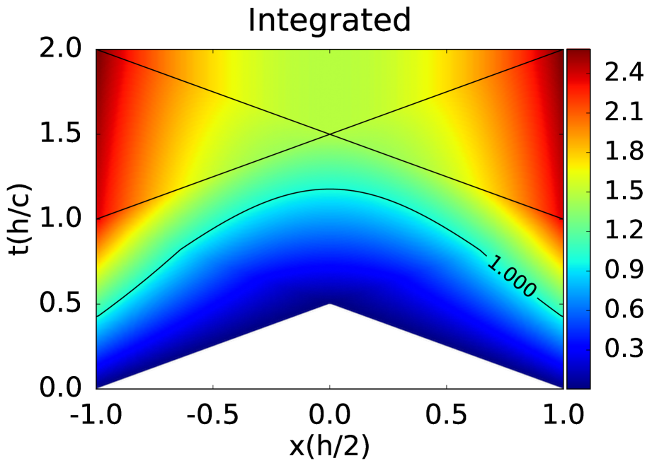
(ii) At the second step we add up the accumulated radiation at position , to obtain the time dependence of energy density distribution, . This is done by integrating the deposited energy from , for each spatial position 111 Due to the flat target geometry and the light pulse strength degradation, the irradiation of the central domains is about three times weaker than in the previously demonstrated spherical configuration Csernai et al., (2018). . See Fig. 3.
Fig. 2 shows the energy deposition per unit time in the plane. Here the decrease of the irradiated energy due to the absorption of the target is compensated by the increasing nano-sphere density. One can see that initially the irradiation reaches only the near side of the target. Later on the irradiation reaches the target from both sides. Here the increased nano-shell density ensures the uniform energy deposition in the middle of the target.
Fig. 3 shows that the integrated energy deposition is nearly homogeneous at time, , when the deposited energy equals the critical value . This contour corresponds to a critical deposited energy , which is sufficient for the ignition (B) or melting (A).
Thus, the increase of absorption in the middle layers is necessary to achieve a isochronous burning front with time-like normal, i.e. simultaneous volume ignition throughout the target.
First let us describe the space-time dynamics for constant absorptivity and without considering the energy loss due to the light degradation during the penetration through the target. (I.e. we assume that the beam energy current is much bigger than the fraction deposited in the target. The same assumption was used in ref.Csernai et al., (2018).)
Let us take the surface integral by using a delta function, selecting the surface element, which can reach the given internal point at a time. The deposited energy at space-time point at by a light front is where is the transverse surface area. As the light front propagated with the speed of light the deposition length is , so the space-time integral for the energy deposition is
| (3) |
along the light front trajectory:
| (4) |
where , and it is assumed that the light front starts from the left and right edge at time . Thus the deposited energy along the light beam trajectory can be characterized by the coordinate only. The deposition can be modified by changing absorptivity in the target by implanting nano-shells.
The average intensity of radiation reaching the surface of the DT pellet (B) amounts to per unit surface (mm2) and unit time (mm/c). Let us take a typical value for the total energy of the ignition pulse to be 50 J, in time 1.04 ps. Then the radiation intensity from both sides is = .
In case of the PLA target (A) from both sides the radiation intensity is . The energy deposition dynamics is illustrated in Figs. 2 and 3.
At time , the light can reach a space-time point (), inside the flat target from the outside surface. At early times it may be that none of the spatial points at positive , are within the backward light-cone of a point (). This domain is white in Figs. 2 and 3. Before the time c there are points, which can be reached from at least one side and there are others which are not. At time c all points of the flat target can be reached from both sides of the flat target. At this time the irradiation from the outside edges stops. At late times, larger than c, the light pulses did reach all internal points () from both sides. At this time all energy deposition to the target is completed. See Fig. 2. The choice of model parameters and their relations are described in Appendix A.
IV Analytic Model
Let us take that the incoming irradiation energy at the flat target surface is . In example B, the total irradiation time is ps, and J from one side and J from both sides together. We introduce the notation that the part of the energy deposited in the target is , at position . The remaining part of the beam energy, , propagates further inwards along the light beam trajectories (4). The irradiation from the two sides is symmetric, and both decrease as propagating inwards. Let us label the left and right sides by indices .
The sum of the deposited and propagating components of the radiation satisfies the relations
Note, that we neglect the energy reflected from the target surface. These propagating components change as
| (5) |
where is the absorption coefficient of the target. In the case if is constant we get
| (6) |
Here the second equation corresponds to the radiation from the surface at , propagating inwards in the direction.
In the same case the deposited energies take the forms:
| (7) |
In the space-time domain where the point can be reached from both sides, the total deposited energy is
| (8) |
Let us first calculate the energy density, , deposited at a space-time point (), in the time interval from earlier times for the l.h.s. and r.h.s of the target. This is an integral of the quantity . For a given point at we get the relation for the integrated energy density
| (9) |
The integral over , runs from the nearest point of the backward light cone , to a later point, , where the parameters and will be described below. Now let us introduce a dimensionless time variable:
and with this notation, the boundaries, , of the above integral are
| (10) |
| (11) |
In integrating over , we add the contributions of those surface elements, from where radiation reaches the internal point at at the same dimensionless time . In the earliest case above the radiation does not reach the point at , then in the second part the radiation from the closer side of the slab reaches but from the opposite point not yet. In the third case radiation reaches from both sides, and so on. In this way the space-time is divided into 4 domains. After the irradiation to the 4th domain is completed the warming up of the target stops because the irradiation finishes in a limited time period.
Thus the integrated energy deposited up to the dimensionless time on the r.h.s. of the system (i.e. for ) is
| (26) | |||
| (27) |
and for .
Neglecting the compression and assuming constant specific heat , we get that , where is the Boltzmann constant, and is the number density of the target matter. Therefore
| (41) |
where is defined as
| (43) |
After substitution of the number density of uncompressed DT ice cm-3, we get
In case of constant one can achieve time-like detonation only in the space-time domain which receives irradiation from both sides, i.e. for values, which satisfy the relation (in the r.h.s. space-time domain). One can show that in this case
| (44) |
| (45) |
The surface of the ignition is characterized by the energy density, , contour line, where is the ignition energy density. The tangent of the contour line, for the points separating its space-like and time-like parts is
| (46) |
So the point where the space-like and time-like parts of the surface meet (for ) is :
| (47) |
where
| (48) |
The ignition starts at and it propagates first slowly inwards. Due to the radiative heat transfer the contour line of ignition, , accelerates inwards, and at it develops smoothly from space-like into a time-like ignition hypersurface.
It is interesting that similar type of gradual development from space-like into time-like regime occurs in the hadronization phase of ultra-relativistic heavy ion collisions Csernai et al., (1994); Heinz et al., (2002); Chatterjee et al., (2006); Molnar et al., (2007); Frodermann et al., (2007); Csernai et al., (2009); Floerchinger et al., (2014); Armesto et al., (2014). If we include radiative heat transfer in our model, the transition from space-like to time-like behavior will be gradual. This, however, requires more involved numerical calculations.
The hyper-surface, where the energy density, const. obtained from the analytical solution shows that time-like behaviour occurs only in the central domain of the flat target. Therefore we cannot achieve uniform volume ignition, and instabilities might develop!
V Variable absorptivity
In order to study the effect of variable absorptivity we reformulated the numerical model to perform all integrals of the model numerically. This enables us to study pellets with nano-shells inside.
In ref. Hu et al., (2014), the Rochester and NIF experimental data were analysed by using opacity data, extracted from basic principles and from comparison with ICF experiments. The absorption coefficient (cm-1), defined by , and the Rosseland and Planck opacities, defined by , were estimated and used to simulate ICF direct ignition experiments.
In our previous calculations we used the absorption coefficient (cm-1), and the approximation that the intensity of the incoming laser light flux is sufficiently large, so that its decrease by the absorption is negligible Csernai et al., (2018). Here we have relaxed this constraint. Also in the previous section we assumed a constant absorptivity, const. Relaxing this simplification changes the situation essentially as it was shown Csernai et al., (2018).
Our equations for and , should now be evaluated numerically based on the same differential equations that were used for the constant absorptivity case.
With increased absorptivity one could reach more rapid heating or energy deposition. Substituting the fusion cross section, the reactivity is increasing up to an energy density analogous to about keV temperature, and then decreases again. Thus, we could aim for a heating up to this energy density with increased light absorption, with smaller pre-compression.
VI Absorptivity by Nanotechnology
Doping ICF pellets with golden nano-shells enables us to achieve the desired variable absorptivity Tanabe, (2016). Nano-shells irradiated by laser light exhibit a resonant light absorption, which can increase the plasmon field- strength by up to a factor of 40-100 or more Prodan et al., (2003); Nordlander et al., (2004). At present experimentally realizable nano-shell sizes range for core sizes of 5-500 nm, and for shell thickness of 1-100 nm.
The resonant light frequency of the nano-shell can be tuned in a very wide range by changing the size and thickness ratio of the nano-shell. If the core versus the shell thickness, , is changed from 2 to 800 the resonant wavelength changed from to nm Loo et al., (2004) with radiation by a beam of specific polarization.
In case of flat targets with irradiation in one direction only, we can use resonant nano-rods instead of spherical nano-shells. In this case, due to the transverse polarization of the light beams, the resonant nano antennas should lay in the transverse plane.
At the resonant frequencies the nano-shells are able to absorb resonantly a rather high portion of incoming light. We can introduce the , and efficiencies, , , and , respectively Lee & El-Sayed, (2005). These coefficients, , describe how much part of the energy of the incoming light is absorbed or scattered by the nano-shell, compared to its geometrical cross-section, G, i.e. for a sphere of radius , .
The nano-shells can be tuned to achieve either larger absorption efficiency or larger scattering efficiency. For our purposes the larger absorption efficiency is more important. Note that the resonance extinction or absorption efficiency can reach a factor 10 or even more Alam & Massoud, (2006).
Most simple materials at room temperature have small absorptance, cm-1 at and around visible light frequencies. The only exceptions are light frequencies that are resonant to some molecular excitation frequencies of the given material. Dense and hot plasma has also similarly low absorptance at high light frequencies above keV. Thus, the initial low temperature target with moderate pre-compression is sufficiently transparent for laser light. This then, with well distributed nano-shells compresses and increases the energy density of the plasma rapidly and simultaneously to ignition level. By then, the hot and dense plasma becomes transparent to radiation, which is still not isotropic but beam directed, just like the accelerated target ions. These latter ones collide with each other in a colliding beam configuration.
The absorptivity of the target can be regulated by the density of implanted nano-shells. Let us denote that the absorption coefficient of the DT fuel target by (cm-1).
If we implant nano-shells, then the absorptivity will increase to
| (49) |
Here the absorptivity of nano-shells is
| (50) |
where , and the nano-shell density is (cm-3).
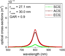
For nano-shells of nm and wall thickness of 3 nm cm2, we obtained from electromagnetic field calculations the absorption cross section, see Fig. 5. For a typical nano-shell density James et al., (2007) of cm3 we obtain an additional absorptivity due to nano shells Csete et al., (2019) of
| (51) |
Based on our computations, we found that 10 layers of sparse core-shell nano-sphere lattices are capable of resulting in a total absorption of 33% and 77% in case of uniform and predefined Gaussian distribution. Even larger absorption improvement can be achieved up to 98% by optimizing the position of the layers. The absorption can be further improved to 66% and 99% via double sided illumination of layers with uniform and optimized Gaussian distribution, respectively. As a result the total absorptivity of the target can be enhanced up to 115 cm-1 / 139 cm-1 & 217 cm-1 / 216 cm-1 & 216 cm-1 / 291 cm-1 via single / double sided illumination of layers with uniform - predefined Gaussian - optimized Gaussian distribution.
On the other hand, we have found (Appendix B), that for optimal simultaneous ignition we need only an additional maximum absorptance from nano shells
| (52) |
in the center of the target. For this central absorptance, assuming that the absorptivity is linearly proportional with the nano-sphere density, we need a central density of of nano-shell density of cm3, and these nano-spheres have a volume of cm3 in 1 cm3. Of course, with higher nano-shell density, higher absorption efficiency can also be achieved. In case of linear configuration, resonant nano-rods, which are parallel to the direction of E-field of polarized irradiation, may provide even larger amplification of the light absorption.
We have studied how the target absorptivity is improved via core-shell type plasmonic nano-shells, via solving the Maxwell equations, and evaluating the ohmic heating. A Deuterium target was considered with periodic boundary conditions in the transverse directions, and we took the target thickness as 0.11 mm.
Previous studies in the literature have shown that core-shell particles of the same composition are capable of resulting in resonance at a specific wavelength in case of different generalized aspect ratios (GAR).
The thin (thick) shell composition results in a narrow (wide) effective scattering cross-section, which is accompanied by large (small) absorption Tam, (2007). As mentioned above, the thin shell composition increases the absorptivity. Accordingly, the generalized aspect ratio, , of silica-gold core-shell particles has been tuned to , in order to get peak absorption and scattering simultaneously at the 800 nm central wavelength of the 1 ps laser pulse. In our calculation the nano-sphere particles are arranged in a sparse, rectangular lattice, so that the near-field interactions are weak, while the lattice resonances do not affect the spectra around 800 nm for this strongly sub-wavelength period (Fig. 4). As a result, a mono-layer exhibits an absorptivity peak at the central wavelength (Fig. 5). Based on our computations, we found that 10 layers of sparse core-shell nano-sphere lattices are capable of resulting in a total absorption larger than 80% of the incoming laser pulse. However, the absorptivity can be further improved to 85% via double sided, compared to single sided irradiation by tuning the phase of the counter propagating waves. Even larger absorptivity improvement can be achieved up to 99% by optimizing the position of the layers. As a result, the total absorption can approach 98% and 99%, and the target absorptivity can be enhanced up to 100 cm-1 and 250 cm-1 via phase tuning and position optimization, respectively. A detailed report of these studies will be published separately Csete et al., (2019).
For DT targets, with densities in the range of g/cm3, and K, absorptivities are obtained in the range of
when the light frequency increased to keV Hu et al., (2014). The typical light mean free path is about 1-10m. Thus, while for low frequency radiation, eV the hot and dense DT target is quite opaque, at higher frequencies or energy, it is much more transparent. This leads to the result that the initial lower energy pulse leads primarily to compression. This effect could be enhanced further with the application of the thin ablator sheet on the surface of the pellet Benredjem et al., (2014).
The additional opacity of nano-shells with typical nano-shell densities can increase the absorptivity up to the values
This makes the fast ignition possibilities very versatile in this light frequency range. We can experiment with variable absorptivity, which is the normal absorptivity of the DT fuel, cm-1 and an additional constant absorptivity from the nano-shells cm-1 at the front and back edge of the pellet (i.e. at ) while in the center, 30.3 cm-1.
The space time profile of the ignition, will then depend on the profile of the nano-shell doping towards the center of the pellet. See Fig. 3.
One can optimize this profile to achieve the largest simultaneous volume ignition domain, which eliminates the possible development of instabilities.
Apart of the large cross section of plasmon excitations, which can enhance the geometrical cross section of the nano-antennas by several orders of magnitude, surface plasmon resonance excitation is a much more efficient process for the quantum mechanical "hot carrier" generation. This process is much faster than the heating via the external hohlraum, and its typical time-scale is around 10-500 fs Liu et al., (2018). This is by orders of magnitude shorter than the irradiation pulse length. Furthermore, at high irradiation intensities, when the temporal spacing between incident photons becomes smaller than the hot carrier relaxation time, the photoluminescence blue-shifts the radiation frequency at large light intensities, due to a multi-photon quantum effects. These two additional effects make the heating with nano-antennas very fast and more effective. These effects depend on the features of the implanted nano-antennas, which can be calculated quantitatively Csete et al., (2019).
Planar metal surfaces reflect most of the incident light, and in this case light absorption is not very efficient. Nevertheless, light absorption can be further enhanced by exciting localized surface plasmon resonances. This produces an antenna effect resulting in light collection from an area that is larger than its physical size. Surface nano-wire arrays may additionally reduce this reflection and can give rise to higher energy densities with a 0.5J laser pulse Purvis et al., (2013); Kaymak et al., (2016).
Here the question arises how the doped nano-shells will behave under compression. The optimal thickness and radius of the golden nano-shells are chosen to achieve resonance condition of the laser irradiation. The stiffness of the shell interior, can be chosen to keep the spherical shape of the nano-particles. From studies of ICF capsules employing DT wetted foam Sacks & Darling, (1987) of similar size small pores, concluded that the in-flight aspect ratio, hydrodynamic efficiency, and hot electron tolerance can be at least as good as for conventional DT targets. The compressed nano-shells will be resonant to higher laser frequencies, which can be taken into account during the nano-shell production.
In the case of nano-rods implanted in the transverse plane with respect to the direction of the light beam, the nano-antenna parameters are not effected essentially by the compression. This makes the tuning of the nano-antennas simpler.
VII Progress of ignition
Depending on the density at ignition, the rate of fusion reactions can be approximated as which may lead to a full DT burning time after the moment of ignition, of the order of 10 ns. This time is 3 orders of magnitude longer than the time to reach uniform ignition with the proposed time-like ignition method. During this time interval the expansion of the hot burning plasma can be substantial, which leads to reduced burning rate and a highly reduced burn-up fraction.
Several physical processes may remedy this problem. The first is pre-compression, as mentioned in the introduction. An initial compression in the beam direction by a factor of 10, increases the fusion rate by a factor of 100, while the laser irradiation pulse with the same pulse energy should be shortened to 53 fs. The beam intensity should also be increased by an order of magnitude to .
This feature, the ion pre-compression by the LWFA configuration. was tested in recent experiments in linear configuration, and reached substantial compression comparable to the one reached at NIF Zhang et al., (2019). 222For comparison the 3D NIF experiments use a linear size compression of 30 and a density increase of almost 1000.
For more realistic estimates we need relativistic fluid dynamical, PICR analysis of the dynamics of the compression and expansion of the system. Possible pre-compression can be achieved by an weaker and longer (so called "low foot") initial irradiation, but still without an ablator layer. The final expansion after the onset of the burning phase, can be suppressed by a continued final "low foot" radiation (in the beam direction). The energetic short ignition pulse accelerates the target matter inwards also, as the deposited light quanta provide an inward momentum. These effects can be evaluated by PICR, relativistic fluid dynamics or relativistic molecular dynamics calculations.
The microscopic features of the ignition increase the chances for faster burning also. The initial motion of the ions at the start of the burning is beam directed and not thermal. It is also enhanced by the laser wake-field acceleration of the ions. Furthermore, non-thermal laser driven plasma-blocks Hora et al., (2017); Sauerbrey, (1996) due to ponderomotive EM forces may additionally accelerate ions in the beam direction to relativistic velocities. This significantly increases the fusion rate, particularly in case of two opposite beams. These effects are recently experimentally verified Zhang et al., (2019).
For optimal choice of a fusion method such effects will be modeled and optimized before experimental tests.
VIII Conclusions and discussions
Using nano-technology for ICF was recently discussed Kaymak et al., (2016); Bargstenm et al., (2017). Placing aligned nano-rods or nano-wires on the surface of the pellet and irradiating it with femtosecond laser pulses of relativistic intensity, leads to a plasma with large electron intensity and pressure. However, this pressure would lead to a pressure driven adiabatic compression and heating, which can lead to Rayleigh-Taylor instabilities, preventing simultaneous volume ignition.
In our model calculations, we have neglected compression as well as the reflectivity of the target matter. The relatively small absorptivity made it possible that the radiation could penetrate the whole target. Our estimated ignition energy is 208 keV/mg, corresponding to the contour in Fig. 3. We see that the critical ignition energy density is reached in about 80% of the target volume simultaneously (i.e. on a time-like hyper-surface). In this domain no instabilities may occur.
We can also apply this model to a moderately pre-compressed target, which is transparent and has larger absorptivity. In this situation the ignition energy density can be somewhat smaller, but we still can optimize the pulse strength and pulse length to achieve the fast, nearly complete ignition of the target. We have considered relatively short and very intensive irradiation, which is relevant for achieving simultaneous, time-like ignition (B). This method leads to a faster energy density increase towards than the growth rate of the Rayleigh-Taylor instability or other instabilities. This can make even an order of magnitude increase in the critical irradiation time. Furthermore if we also consider the smoothing effect of radiation dominated ignition front (B) then the critical irradiation time can be even longer. This could only be estimated with 3+1D RFD calculation.
Finally we want to point out that if we neglect the relativistic effects, the theory would be far-fetched from reality. It is important to use the proper relativistic treatment to optimize the fastest, more complete ignition, with the least possibility of instabilities, which reduce the efficiency of ignition.
Acknowledgements
Enlightening discussions with István Földes and Gergő Pokol, Péter Rácz, Kirill Taradiy and Sándor Varró, are gratefully acknowledged. This work is supported in part by the Institute of Advance Studies, Kőszeg, Hungary, and the Frankfurt Institute for Advanced Studies.
Appendix A: Parameters
Based on the NIF results Le Pape et al., (2018) the necessary ignition energy of the DT target (B) is kJ/mg. Then assuming a J laser pulse energy, we can ignite a DT target of mass g. The density of DT ice is g/cm3, which leads to a target volume of mm3. For a minimal target surface, the diameter and height of the DT target cylinder becomes mm, and its cross section is mm2.
The critical energy density for ignition is:
MJ/cm3 (kJ/mm3),
while the required pulse duration is
ps.
During this time interval we should deposit the
total pulse energy, to the target, which leads to an initial
energy flux, at the flat surface of the target
kJc/mm4.
Therefore we get kJc/mm2.
Taking into account that in the beam direction the light front propagates with the speed of light (in the target material), we get the deposited energy
and we can introduce the linear deposited surface energy density, , inside the target as
along a light beam starting at . From the incoming surface energy density a part, , is deposited in the target material:
and the remaining lesser part continues to propagate along the light beam as described in Section IV.
Appendix B: Absorptivity
For constant absorptivity only slow heating of the target is possible, see Fig. 6.
In our numerical calculations with nano-shells implanted in the target to increase central absorption (see Figs. 2 and 3), we used the distribution:
Here the length scale, , is chosen so that corresponds to mm. The edge absorptivity of the fuel is 1.0 cm-1, then from the nano-shells 9.10 cm-1, and 20.2 cm-1. Thus in the centre the absorbance is 30.3 cm-1. For this absorbtance parameters we need a modest density of nano-spheses embedded into the target fuel. In the center cm while at the outside edges even less cm In the center of the target material the nano-shells will occupy only % of the volume.
With these absorption parameters only 0.25% of the energy of the incoming laser pulse reaches the opposite side of the target. Thus, the expectation is an energy balance with a possible minimum of loss.
References
References
- Csernai et al., (2018) Csernai, L.P., Kroo, N. and Papp, I. (2018). Radiation dominated implosion with nano-plasmonics, Laser and Particle Beams 36, 171-178. DOI: 10.1017/S0263034618000149
- Csernai et al., (2017) Csernai, L.P., Kroo, N. and Papp, I. (2017). Procedure to improve the stability and efficiency of laser-fusion by nano-plasmonics method. Patent # P1700278/3 of the Hungarian Intellectual Property Office.
- Landen et al., (2012) Landen, O.L.,Benedetti, R., Bleuel, D., Boehly, T.R., Bradley, D.K., et al., (2012). Plasma Phys. Control. Fusion 54, 124026.
- Robey et al., (2012) Robey, H.F., Boehly, T.R., Celliers, P.M., Eggert, J.H., Hicks, D., et al., (2012). Shock timing experiments on the National Ignition Facility: Initial results and comparison with simulation. Physics of Plasmas 19, 042706.
- Nora et al., (2015) Nora, R., Theobald, W., Betti, R., Marshall, F.J., Michel, D.T., et al., (2015). Gigabar Spherical Shock Generation on the OMEGA Laser. Phys. Rev. Lett. 114, 045001.
- Zhang et al., (2019) G. Zhang, M. Huan, A. Bonasera, Y.G. Ma, B.F. Shen, et al., (2019). Nuclear probes of an out-of-equilibrium plasma at the highest compression arXiv: 1812.06868 and Phys. Lett. A 383, 2285-2289.
- Csernai, (1987) Csernai, L.P. (1987). Detonation on a time-like front for relativistic systems. Zh. Eksp. Teor. Fiz. 92, 379-386.
- Zeldovich & Raiser, (1966) Zeldovich, Y.B. and Raiser, Y.P. (1966). Physics of Shock Waves and High-Temperature Hydrodynamic Phenomena. Nauka, Moscow, 1966.
- Gyulassy & Csernai, (1986) Gyulassy, M. and Csernai, L.P. (1986). Baryon recoin and the fragmentation regions in ultrarelativistic nuclear collisions, Nucl. Phys. A 460, 732.
- Csernai & Strottman, (2015) Csernai, L.P. and Strottman, D.D. (2015). Volume ignition via time-like detonation in pellet fusion. Laser and Particle Beams 33, 279-282.
- Hu et al., (2014) Hu, S.X., Collins, L.A., Goncharov, V.N., Boehly, T.R., Epstein, R., et al., (2014). First principle opacity table of warm dense deuterium for inertial-confinement-fusion applications. Phys. Rev. E 90, 033111.
- Aladi et al., (2014) M. Aladi, J.S. Bakos, I.F. Barna, A. Czitrovszky, G.P. Djotyan, et al., (2014). Pre-Excitation Studies for Rubidium-Plasma Generation. Nucl. Instr. Meth. in Physics Res. A 740, 203.
- Antonelli et al., (2018) L. Antonelli, F. Barbato, P. Neumayer, D. Mancelli, J. Trela, et al., (2018). arXiv: 1801.10049 [physics.plasm-ph].
- Le Pape et al., (2018) S. Le Pape, L. F. Berzak Hopkins, L. Divol, A. Pak, E. L. Dewald, et al., (2018). Phys. Rev. Lett. 120, 245003.
- Csernai et al., (1994) Csernai, L.P. (1994). Introduction to Relativistic Heavy Ion Collisions. (John Wiley & Sons, Cichester, England);
- Heinz et al., (2002) Heinz, U.W. and Kolb, P.F. (2002). Emission angle dependent pion interferometry at RHIC and beyond. Phys. Lett. B 542, 216.
- Chatterjee et al., (2006) Chatterjee, R., Frodermann, E.S., Heinz, U. and Srivastava, D.K. (2006). Elliptic flow of thermal photons in relativistic nuclear collisions. Phys. Rev. Lett. 96, 202302.
- Molnar et al., (2007) Molnar, E., Csernai, L.P., Magas, V.K., Lazar, Z.I., Nyiri, A. et al., (2007). Covariant description of kinetic freeze-out through a finite time-like layer. J. Phys. G 34, 1901.
- Frodermann et al., (2007) Frodermann, E., Chatterjee, R. and Heinz, U. (2007). Evolution of pion HBT radii from RHIC to LHC - Predictions from ideal hydrodynamics. J.Phys. G 34, 2249.
- Csernai et al., (2009) Csernai, L.P., Cheng, Y., Horvat, S., Magas, V., Strottman, D. et al., (2009). Flow analysis with 3-dim ultra-relativistic hydro. J.Phys. G 36, 064032.
- Floerchinger et al., (2014) Floerchinger, S. and Wiedemann, U.A. (2014). Kinetic freeze-out, particle spectra, and harmonic-flow coefficients from mode-by-mode hydrodynamics. Phys. Rev. C 89, 034914.
- Armesto et al., (2014) Armesto, N., Dainese, A., d’Enterria, D., Masciocchi, S., Roland, et al., (2014). Heavy-ion physics studies for the Future Circular Collider. Nucl. Phys. A 931, 1163.
- Tanabe, (2016) Tanabe, K. (2016). Plasmonic energy nanofocusing for high-efficiency laser fusion ignition. Japanese Journal of Applied Physics 55, 08RG01.
- Prodan et al., (2003) Prodan, E., Radloff, C., Halas, N.J. and Nordlander, P. (2003). A hybridization model for the plasmon response of Complex Nanostructures. Science 301, 419-422.
- Nordlander et al., (2004) Nordlander, P. and Prodan, E. (2004). Plasmon hybridization in nanoparticles near metallic surfaces. Nano Lett. 4, 2209-2231.
- Loo et al., (2004) Loo, C., Lin, A., Hirsch, L., Lee, M.-H., Barton, J., et al., (2004). Nanoshell-Enabled Photonics-Based Imaging and Therapy of Cancer, Technology in Cancer Research & Treatment (ISSN 1533-0346) 3 (1) (Adenine Press).
- Lee & El-Sayed, (2005) Lee, K-S. and El-Sayed, M.A. (2005). Dependence of the Enhanced Optical Scattering Efficiency Relative to That of Absorption for Gold Metal Nanorods on Aspect Ratio, Size, End-Cap Shape and Medium Refractive Index. J. Phys. Chem. B 109, 20331-20338.
- Alam & Massoud, (2006) Alam, M. and Massoud, Y. (2006). A Closed-Form Analytical Model for Single Nanoshells. IEEE Transactions on nanotecnology, 5, 265.
- James et al., (2007) James, W.D., Hirsch, L.R., West, J.L., O’Neal, P.D. and Payne, J.D. (2007). Application of INAA to the build-up and clearance of gold nanoshells in clinical studies in mice. J. Radioanalytical and Nucl. Chem., 271, 455-459.
- Tam, (2007) F. Tam (2007). Mesoscopic nanoshells: Geometry-dependent plasmon resonances beyond the quasistatic limit. The Journal of Chemical Physics, 127, 204703.
- Csete et al., (2019) M. Csete, O. Fekete, A. Szenes, D. Vass et al. to be published.
- Benredjem et al., (2014) Benredjem, D., Pain, J.C., Gilleron, F., Ferri, S. and Calisti, A. (2014). Opacity profiles in inertial confinement fusion. J. Phys. C.S. 548, 012009.
- Liu et al., (2018) Liu, J.G., Zhang, H., Link, S. and Nordlander, P. (2018). Relaxation of Plasmon-Induced Hot Carriers. ACS Photonics 5, 2584-2595. DOI: 10.1021/acsphotonics.7b00881
- Purvis et al., (2013) Michael A. Purvis, Vyacheslav N. Shlyaptsev, Reed Hollinger, Clayton Bargsten, Alexander Pukhov, et al., (2013). Relativistic plasma nanophotonics for ultrahigh energy density physics, Nature Photonics 7, 796-800.
- Sacks & Darling, (1987) Sacks, R.A. and Darling, D.H. (1987). Direct Drive Cryogenic ICF Capsules Employing D-T Wetted Foam. Nuclear Fusion 27, 447.
- Hora et al., (2017) Hora, H., Eliezer, S., Nissim, N., and Lalousis, P. (2017). Non-thermal laser driven plasma-blocks for proton boron avalanche fusion as direct drive option. Matter and Radiation at Extremes 2, 177-189.
- Sauerbrey, (1996) Sauerbrey, R. (1996). Acceleration in femtosecond laser-produced plasmas. Physics of Plasmas 3, 4712. DOI: 10.1063/1.872038
- Kaymak et al., (2016) Kaymak, V., Pukhov, A., Shlyaptsev, V.N. and Rocca, J.J. (2016). Nano-scale ultra-dense Z-pinches formation from laser-irradiated nanowire arrays. Phys. Rev. Lett. 117, 035004. DOI: 10.1103/PhysRevLett.117.035004
- Bargstenm et al., (2017) Bargstenm, C. et al. (2017). Energy penetration into arrays of aligned nanowires irradiated with relativistic intensities: Scaling to Terabar pressures. Sci. Adv. 3, e1601558.