Lens-based Millimeter Wave Reconfigurable Antenna NOMA
Abstract
This paper proposes a new multiple access technique based on the millimeter wave lens-based reconfigurable antenna systems. In particular, to support a large number of groups of users with different angles of departures (AoDs), we integrate recently proposed reconfigurable antenna multiple access (RAMA) into non-orthogonal multiple access (NOMA). The proposed technique, named reconfigurable antenna NOMA (RA-NOMA), divides the users with respect to their AoDs and channel gains. Users with different AoDs and comparable channel gains are served via RAMA while users with the same AoDs but different channel gains are served via NOMA. This technique results in the independence of the number of radio frequency chains from the number of NOMA groups. Further, we derive the feasibility conditions and show that the power allocation for RA-NOMA is a convex problem. We then derive the maximum achievable sum-rate of RA-NOMA. Simulation results show that RA-NOMA outperforms conventional orthogonal multiple access (OMA) as well as the combination of RAMA with the OMA techniques.
I Introduction
Global mobile data traffic is projected to grow exponentially in the coming several years. A similar trend is foreseen for the number of users. Specifically, fifth generation (5G) networks are envisioned to serve more than one million users per [1]. To meet these demands, millimeter wave (mmWave) communications and non-orthogonal multiple access (NOMA) have emerged as two key technologies.
The large unused spectrum available at the mmWave band (30-300 GHz) offers a great potential for the transmission of a substantial volume of data. Short wavelength of the mmWave band allows for employing a huge number of antenna elements at small space. To exploit this unique property, several designs have been proposed for mmWave systems. In one design, each antenna element is connected to one radio frequency (RF) chain which is called digital beamforming system. The system achieves a high throughput, however, is costly both in terms of hardware complexity and power consumption. To support multiple streams while keeping the hardware complexity low, hybrid beamforming systems are proposed [2]. In this design, each RF chain is connected to the antennas via phase-shifters (PSs). In another design, the antennas are positioned on the surface of a lens and associated with RF chains via a switch network. Such a system is termed beamspace multiple-input multiple-output (MIMO) [3]. The above systems mostly focus on improving the spectral efficiency in the mmWave spectrum, however, they fail to overcome severe path loss and shadowing. To this aim, recently, the concept of lens-based reconfigurable antenna MIMO (RA-MIMO) has been introduced for mmWave communications [4, 5]. In lens-based antennas, each RF chain is connected to just one reconfigurable antenna. Further, each reconfigurable antenna is able to steer multiple independent beams.
NOMA is another enabling technology for 5G. NOMA in the power domain uses superposition coding at the transmitter and successive interference cancellation at the receiver to simultaneously serve multiple users and enhance spectral efficiency in multi-user scenarios [6, 7]. In mmWave communications, due to high path loss, users with different locations experience considerably different channel gains. This implies that mmWave systems better suit power domain NOMA which offers better spectral efficiency compared to that of orthogonal multiple access (OMA) techniques. In light of this, several groups have studied the integration of NOMA in mmWave systems, i.e., mmWave-NOMA [8, 9]. However, the major limitation with the current mmWave-NOMA technique is that the number of RF chains is the same as the number of NOMA groups. This limits the number of simultaneously supported user groups.
In our previous work [10], we have shown that the rate performance of a multiuser system with a lens-based reconfigurable antenna [4] is degraded when NOMA is applied. To tackle this issue, a new technique named reconfigurable antenna multiple access (RAMA) was proposed in [10]. Although RAMA achieves a higher sum-rate than both OMA and NOMA, its operation is limited to only one user per beam. To overcome this limit, we propose a new multiuser technique which integrates RAMA and NOMA, and is referred to as RA-NOMA. In RA-NOMA, each antenna element is connected to all RF chains. Users are grouped into two different sets based on the angle of departures (AoDs) and the users’ channel gain. The users with different AoDs and comparable channel gains are supported via RAMA while the users with the same AoDs but different channel gains are served via NOMA. This technique introduces a new degree of freedom for grouping the users without adding RF chains. We show that, the multi-beam NOMA power allocation problem can be transformed into a convex problem over one beam. Further, the feasibility conditions of the power allocation problem are assessed. Numerical results reveal that the proposed design outperforms OMA and the combination of RAMA with conventional OMA techniques in terms of sum-rate.
The paper is organized as follows. In Section II, a brief background on RAMA is provided. Section III proposes the RA-NOMA technique. Section IV presents the power allocation in the downlink of RA-NOMA. In Section V, simulation results are presented. Finally, Section VI concludes the paper.
Notations: Hereafter, . Also, and denote the expected value and absolute value operators, respectively. Small letters and bold small letters show scalars and vectors, respectively. Further, denotes the 1-norm of vector and superscript denotes the transpose operator.
II Background
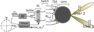
We consider the downlink transmission in a single-cell mmWave communication system with a base station (BS) serving multiple users. The BS is equipped with a lens-based reconfigurable antenna and the users are provided with a single antenna. The reconfigurable antenna comprises of following blocks: one RF chain, a splitter, a PS, a switching network, tapered slot antennas (TSAs), and a spherical lens located in front of the TSAs [4]. The system is shown in Fig. 1. The scheme in Fig. 1 which uses one RF chain is based on the design in [10], and we refer to the system as RAMA.
The mmWave propagation environment is modeled by widely adopted multipath Saleh-Valenzuela channel model [2, 3]. Suppose only one propagation channel is selected from the transmitter to each user. So, the channel for User is given by where denotes the channel gain of User , denotes the antenna array response vector of the BS, and () denotes the azimuth (elevation) AoD. The array vector is defined as
| (1) |
where and for and . and denote the number of rays of axis and axis, respectively. Also, and are the antenna spacing and the wavelength, respectively.
In what follows, we briefly describe RAMA. In RAMA, we transmit only the intended signal for each user at the same time/frequency/code blocks. Assume only two users are available. The intended signals for Users and 2 are denoted by and , respectively. Assume that , for , is drawn from a phase shift keying (PSK) constellation111Notice that while RAMA is compatible with all standard constellations, throughout this paper, we consider only PSK constellation. For more details on the other constellations, the interested reader is referred to [10]. and . Then, can be expressed in terms of as
| (2) |
where and where denotes the difference between the phases of and . This module is implemented by a phase detector block shown in Fig. 1. In the above design, only one of the signals, say , is upconverted by the RF chain block and the whole power is allocated to that signal. The phase detector block calculates the phase difference between and , i.e., . This block is shown as a black box in Fig. 1. The switch network selects two TSA feeds, e.g., the green (TSA1) and yellow (TSA2) feeds in Fig. 1. The signals corresponding to TSAs 1 and 2 are given by and , respectively.
As illustrated in Fig. 1, in the reconfigurable antenna, a spherical electromagnetic lens is positioned in front of the antenna array (TSA feeds). The lens operates as a passive PS network that shifts the phase of the signal with different delays such that when a plane wave like hits the lens from one side, the output on the other side is only the magnitude of the wave [11]. Since transmission is directional in mmWave bands, each RAMA user receives only its intended signal, for =1, 2, i.e.,
| (3) |
where denotes the noise term which is additive white Gaussian with zero-mean and variance . It is worth mentioning that the lens constructively delays the phase of elements of the antenna array response vector, however, the PSs change the phase of the in a way to obtain the desired signals, i.e., . Here, the splitter routes input power equally between its outputs, i.e., . This is due to the fact that equally-divided power splitters can reduce hardware complexity compared to the dynamic counterpart. The achievable rate of RAMA for each user under equal power allocation () is obtained as [10]
| (4) |
In [10] it is shown that when users experience different AoDs (i.e., transmission paths), RAMA is a more efficient than NOMA to serve multiple users.
It is noteworthy that, here, we assume that no interference is imposed from the signal intended for User 1 on User 2 and vice versa. This assumption is very well justified since the proposed lens based slotted reconfigurable antenna results in highly directional beams with very limited sidelobes [12]. Moreover, due to significant path loss and shadowing in mmWave frequencies we do not expect the signals from the sidelobes to reach the unintended user222Detail analysis of the impact of sidelobes on inter-beam interference in RAMA is subject of future research..
III The Proposed RA-NOMA Technique
Recall that RAMA is only applicable to users with different AoDs and in directional transmission whereas NOMA is mostly applied for users with the same AoDs but different channel gains. This points out that the two techniques can be used to serve two different groups of users. Hence, there is a unique opportunity to integrate RAMA with NOMA, i.e., RA-NOMA, to add a degree of freedom to serve far more users without increasing the number of RF chains.
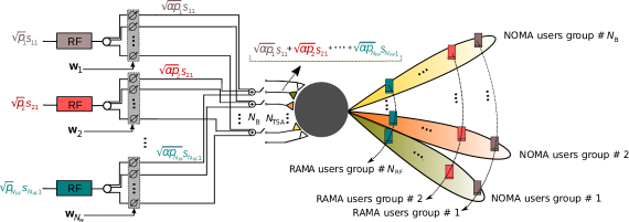
Toward this goal, we divide the users into two groups based on their AoDs and channel gains as: i) RAMA and ii) NOMA groups. The users in the RAMA group are assumed to have distinctive AoDs but relatively similar channel gains. The users within the NOMA group are assumed to have the same AoDs but different channel gains. Note that probability of having users with the same AoDs and same channel gains is small. However, the probability of having users with similar AoDs or similar channel gains is high in 5G networks due to dense deployment [13]. Fig. 2 depicts a potential configuration for RA-NOMA users. The users with the same color belong to the same RAMA group. Further, those users covered by the same beam belong to the same NOMA group.
In our proposed design, we assume that the splitters have a fixed number of outputs with equal power. Therefore, the number of beams supporting the NOMA groups is fixed. We assume that the number of beams, i.e., the NOMA groups, is . The number of RAMA groups can vary up to the number of RF chains. Therefore, is the number of users supported by each beam. Hence, the total number of the served users via RA-NOMA is .
The transmission power of the th RF chain, , i.e., total allocated power to the th group of RAMA users, is assumed to be . Also, denotes the allocated power to each user in the th RAMA group in which . We let denote the intended signal for the th group of RAMA users before the th RF chain. At the th PS, the vector is designed based on (2), such that we have
| (5) |
and
| (6) |
where, contains the intended signals for the users in the th RAMA group, and denotes the difference between the phases of and in the th RAMA group. Considering the allocated power of each NOMA group, the superposition coded signal of the th beam is given by
| (7) |
Let refer to the channel gain of a user in the th RAMA group in the th beam and we refer to this user as User . In the th beam or equally the th NOMA group, without loss of generality, we assume the channels of users are sorted as . The received signal by User becomes
| (8) |
where is the additive white Gaussian noise with variance . As it is seen, inter-beam interference is removed. In each beam, with using NOMA, successive detection is carried out in descending order. Therefore, the achievable rate of User is obtained as
| (9) |
IV Power Allocation For Downlink RA-NOMA
In this section, we study power allocation for the proposed RA-NOMA system. Let be the transmission powers of the RAMA groups. Our objective is to optimize the power allocation to maximize the sum achievable rate under the total power and individual minimum rate constraints for users as follows {maxi!}[2] p ∑_k=1^N_B ∑_i=1^N_RF R_ik \addConstraint∑_i=1^N_RF p_i≤P_max \addConstraintR_ik≥¯R_ik,∀i,k\addConstraintp≥0, where, is the maximum transmit power of the system and denotes the minimum (required) rate at User . The defined power allocation problem above can ensure user fairness by assuming the same minimum rate requirement for all users in the constraint (IV).
Lemma 1.
The maximum of minimum rate requirement in the th RAMA group defines the minimum power requirement for the th RF chain.
Proof.
See Appendix A. ∎
Using Lemma 1, it is easy to show that each beam achieves the same transmission rate. Therefore, the power optimization problem in (IV) is transformed into the power allocation over one beam. We define , , for , and . Considering the above, the optimization problem over one beam is as follows. {maxi!}[2] p ∑_i=1^N_RF log_2(—hi—2ai+ σ2α—hi—2ai+1+ σ2α) \addConstraint∑_i=1^N_RF p_i≤P_max \addConstraint—h_i—^2 a_i + σ^2 / α≥2^¯R_i(—h_i—^2 a_i+1+ σ^2 / α),∀i \addConstraintp≥0. The optimization problem in (1) has a feasible solution if there is any distribution of such that satisfies the minimum rate requirements while meeting the constraint in (1). Therefore, we consider minimizing the total transmission power with rate constraints for users as {mini!} p ∥p∥_1 \addConstraintR_i≥¯R_i,∀i. We define the answer to the optimization problem in (1) as and the feasibility condition of problem (1) becomes . Due to lack of space, we use the results in [14] for solving (1) and the optimal power for the can be derived as
| (10) |
Therefore, the optimal value of (1) is . By some manipulations we have
| (11) |
as the feasibility condition of the optimization problem in (1).
The objective function in (1) is proved to be concave in [15]. Since the constraints in (1) are linear, the optimization problem is convex. Therefore, the solution of the problem can be found by solving the Karush-Kuhn-Tucker (KKT) conditions [16]. The Lagrangian function of the problem (1) is given by
| (12) | ||||
where, and are the non-negative Lagrangian multipliers associated with (1) and (1), respectively. From this point, the KKT conditions and solution is the same as [15]. Therefore, to save space and avoid replication, we just state the results of the solution as follows
-
•
The Lagrange multiplier is greater than zero and constraint (1) holds with equality.
-
•
The Lagrange multipliers for are greater than zero and the solution of the problem depends on the multiplier .
- •
Consequently, the optimal value of problem (IV) is that of problem (1) multiplied by .
V Simulation Results
In this section we evaluate the performance of the proposed RA-NOMA by using numerical analysis. We consider users to be served by RA-NOMA. The users are scheduled in three RAMA groups and four beams as shown in Fig. 2. The minimum rate requirements are considered to be equal and set to (b/s/Hz). We define transmit signal-to-noise ratio (SNR) as the normalized transmit power with respect to . We assume that the users in RAMA groups have dB.
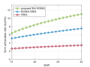
The performance of RA-NOMA is compared with two access methods: OMA and RAMA-OMA. Table I provides the number of required RF chains and time slots for the mentioned techniques. Fig. 3 represents sum-rate of the three techniques versus the transmit SNR. The simulation results are normalized for one time slot for all three techniques. As it is shown, the proposed RA-NOMA outperforms OMA and RAMA-OMA techniques in terms of sum-rate with equal power budget at the transmitter. It should be noticed that RA-NOMA is not compared with NOMA technique. This is because user grouping regarding Fig. 2 may not be appropriate for deploying NOMA technique. As such, NOMA technique for this grouping requires four RF chains which is not efficient in terms of energy consumption and hardware expenses. One would deploy NOMA with lens antenna and three RF chains for users. The grouping should contain three beams and supports four users per each beam. However, due to lack of space, the comparison between RA-NOMA and NOMA with different user groupings will be provided in the extended version of this article.
| OMA | RAMA-OMA | RA-NOMA | |
|---|---|---|---|
| Number of RF chains | 1 | 1 | 3 |
| Number of time slots | 12 | 3 | 1 |
VI Conclusion and Future Work
In this paper, we proposed RA-NOMA as a new multiple access technique for mmWave lens-based reconfigurable antennas. To achieve this, we take advantage of both RAMA and NOMA techniques. Due to the directive and independent beams steered by the lens antennas, the inter-cluster interference between the users is eliminated. Further, the proposed RA-NOMA simultaneously supports a large number of users by using a single BS in the downlink and less number of RF chains compared to the existing mmWave-NOMA technique. The maximum achievable downlink rate of RA-NOMA is derived and the simulation results demonstrate that the proposed RA-NOMA achieves higher sum-rate compared to RAMA and conventional OMA techniques. For future work, the authors will investigate the application of learning techniques in clustering and power allocation [17] of the proposed RA-NOMA technique.
Appendix A
The minimum rate requirement constraint in (IV) imposes the following condition for .
| (14) |
We recall that users of the th RAMA group are scheduled with almost equal channel gains, i.e, , for . Therefore, the term has almost the same value for all users in one RAMA group. So, the minimum power of the th RAMA group, th RF chain, is lower bounded by the maximum of the term , i.e., .
References
- [1] H. Zhang, Y. Dong, J. Cheng, M. J. Hossain, and V. C. Leung, “Fronthauling for 5G LTE-U ultra dense cloud small cell networks,” IEEE Wireless Commun. Mag., vol. 23, no. 6, pp. 48–53, Dec. 2016.
- [2] O. El Ayach, S. Rajagopal, S. Abu-Surra, Z. Pi, and R. W. Heath, “Spatially sparse precoding in millimeter wave MIMO systems,” IEEE Trans. Wireless Commun., vol. 13, no. 3, pp. 1499–1513, Mar. 2014.
- [3] J. Brady, N. Behdad, and A. M. Sayeed, “Beamspace MIMO for millimeter-wave communications: System architecture, modeling, analysis, and measurements,” IEEE Trans. Antennas Propagat., vol. 61, no. 7, pp. 3814–3827, Jul. 2013.
- [4] M. A. Almasi, H. Mehrpouyan, V. Vakilian, N. Behdad, and H. Jafarkhani, “Reconfigurable antennas in mmWave MIMO systems,” arXiv preprint arXiv:1710.05111, 2017.
- [5] ——, “A new reconfigurable antenna MIMO architecture for mmWave communication,” in Proc. IEEE ICC, pp. 1–7, May 2018.
- [6] Y. Saito, A. Benjebbour, Y. Kishiyama, and T. Nakamura, “System-level performance evaluation of downlink non-orthogonal multiple access (NOMA),” in Proc. IEEE PIMRC, pp. 611–615, Sep. 2013.
- [7] M. Vaezi, Z. Ding, and H. V. Poor, “Multiple access techniques for 5G wireless networks and beyond,” Springer, 2019.
- [8] J. Cui, Y. Liu, Z. Ding, P. Fan, and A. Nallanathan, “Optimal user scheduling and power allocation for millimeter wave NOMA systems,” IEEE Trans. Wireless Commun., vol. 17, no. 3, pp. 1502–1517, Mar. 2018.
- [9] M. A. Almasi, M. Vaezi, and H. Mehrpouyan, “Impact of beam misalignment on hybrid beamforming NOMA for mmWave communications,” IEEE Trans. Commun., to appear.
- [10] M. A. Almasi, H. Mehrpouyan, D. Matolak, C. Pan, and M. Elkashlan, “Reconfigurable antenna multiple access for 5G mmWave systems,” in Proc. IEEE ICCW, pp. 1–6, May 2018.
- [11] M. A. B. Abbasi, V. F. Fusco, H. Tataria, and M. Matthaiou, “Lens-based beamformer for low-complexity millimeter-wave cellular systems,” in Proc. the 8th ESA Workshop on Millimetre-Wave Techn. and Applications, Dec. 2018.
- [12] B. Schoenlinner, X. Wu, J. P. Ebling, G. V. Eleftheriades, and G. M. Rebeiz, “Wide-scan spherical-lens antennas for automotive radars,” IEEE Trans. Microwave Theory Tech., vol. 50, no. 9, pp. 2166–2175, Sep. 2002.
- [13] X. Ge, S. Tu, G. Mao, C. Wang, and T. Han, “5G ultra-dense cellular networks,” IEEE Commun. Mag., vol. 23, no. 1, pp. 72–79, Feb. 2016.
- [14] J. Choi, “NOMA: Principles and recent results,” in Proc. IEEE ISWCS, pp. 349–354, Aug. 2017.
- [15] Z. Yang, W. Xu, C. Pan, Y. Pan, and M. Chen, “On the optimality of power allocation for NOMA downlinks with individual QoS constraints,” IEEE Commun. Lett., vol. 21, no. 7, pp. 1649–1652, Jul. 2017.
- [16] S. Boyd and L. Vandenberghe, Convex Optimization. New York, NY, USA: Cambridge University Press, 2004.
- [17] R. Amiri, H. Mehrpouyan, L. Fridman, R. K. Mallik, A. Nallanathan, and D. Matolak, “A machine learning approach for power allocation in HetNets considering QoS,” in Proc. IEEE ICC, pp. 1–7, May 2018.