ELECTROPOLYMERIZATION: STUDIES AND APPLICATIONS
Chapter 0 ELECTROCHEMICAL SYSTEMS: ELECTRODES AND DOUBLE LAYERS
Asghar Aryanfar111Corresponding Author: Email: aryanfar@caltech.edu∗,†, Agustin J. Colussi∗, Laleh M. Kasmaee∗, Michael R. Hoffmann∗
California Institute of Technology, 1200 E California Blvd, Pasadena, CA 91125
Bahçeşehir University, 4 Çırağan Cad, Beşiktaş, Istanbul, Turkey 34349
1 Abstract
Electropolymerization plays a critical role in the electrochemical systems. In this chapter, we address such role within the context of interplay between kinetics and energetics. The trains of chin radical reactions leads to the formation of thin films in electrochemical devices. The structure of so-called solid electrolyte interphase (SEI) during the initial charge/discharge cycles of the device of any kind (i.e. rechargeable battery) on the surface of electrode directly controls the the ultimate stability and longevity. In this chapter, we study the morphological evolution of SEI, both in terms of transport and thermodynamics within quantitative and qualitative contexts.
2 Introduction
Electropolymerization plays an important role in the operation of rechargeable batteries in portable electronics and electric vehicles. As an alkaline metal can react with the most organic solvents, a surface film is formed during the initial charging/discharging processes. This electrically insulating and ionically conductive interface is named as the solid electrolyte interphase (SEI). [1]
Electropolymerization typically occurs in the double layer region (DL herein after). Also called as electrical double layer (EDL), such structure appears on the surface of an object when it is exposed to a fluid. The object might be a solid particle, a gas bubble, a liquid droplet, or a porous body. The DL refers to two parallel layers of charge surrounding the object. The first layer, the surface charge (either positive or negative), consists of ions adsorbed onto the object due to chemical interactions. The second layer is composed of ions attracted to the surface charge via the Coulomb force, electrically screening the first layer. This second layer is loosely associated with the object. It is made of free ions that move in the fluid under the influence of electric attraction and thermal motion rather than being firmly anchored. It is thus called the "diffuse layer".
Interfacial DLs are most apparent in systems with a large surface area to volume ratio, such as a colloid or porous bodies with particles or pores (respectively) on the scale of micrometers to nanometers. However, DLs are important to other phenomena, such as the electrochemical behavior of electrodes. [2]
This layer and includes various organic and inorganic components. On one hand, the formation of the SEI intrinsically consumes the anode and electrolyte, leading to a low efficiency. Consequently, the SEI effectively prevents the further physical contact between Li and the solvent, therefore making Li dynamically stable in certain organic electrolytes.[3] In particular, the SEI can adjust the distribution of Li ions from the bulk electrolyte to the anode. This layer is merely the result of competitive desolvation of ionic compounds on the organic electrolytes. [4]
The SEI ultimately covers the Li electrodes in multilayer surface films composed of organic or inorganic Li salts. Thereby, applying an electrical field to Li electrodes enables electrochemical Li dissolution and deposition to occur through these surface films. [5]
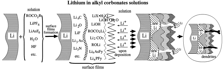
The Figure 1 shows that upon formation of SEI layer, it interferes the morphology of deposition and therefore the upcoming lithium ions cannot afford to perform uniform deposition.
Looking closer to the morphology, SEI is thin and fragile film and stabilizes the redox reaction on the electrode surface. While this film doesn’t let bigger organic compounds to reduce further, it is conductive to smaller charge carrier candidate ions such as lithium () , Nickel (), Magnesium () or Zinc ().
The morphology of SEI is highly effective on the rechargeable lithium metal batteries as an optimal energy storage devices [6]. has an exceptional facility for growing dendrites, a feature that causes battery degradation and ultimately failure [7, 8, 9]. Inhibition of such microstructures hinge on SEI generated from the decomposition of most organic solvents at the negative potentials required to reduce [10]. The importance generally ascribed to SEI is most objectively attested by recent reports which emphasized that ‘. . .SEI formation is the most crucial and least understood phenomena impacting battery technology. . .’ [11], and ‘. . .constructing stable and efficient SEI is among the most effective strategies to inhibit the dendrite growth and achieve superior cycling performance. . .’ [12]. Previous attempts at improving SEI properties have variously resorted to ‘. . .electrolyte additives and surface modification of the cathode…(which) have been shown to improve the formation of an effective SEI layer. . .’ and led to the conclusion that ‘. . .the formation of the SEI depends largely on electrode materials, electrolyte salts, and solvents involved. . .’ [13].
| I | |
|---|---|
| II | + |
| III | + |
The composition and structure of SEI have also been intensively investigated by diverse techniques, such as XPS, solid state NMR [14], ellipsometry [15], sum-frequency generation spectroscopy [16], electron microscopies [17], neutron scattering [18], AFM [19], electron paramagnetic spectroscopy and matrix assisted laser desorption ionization (MALDI) time of flight mass spectrometry [20]. Recent reviews, however, have acknowledged that ‘…many strategies have been proposed to modify SEI structure. However, the modifying process is still out of control in a bulk cell because the thickness, density and ion conductivity cannot yet be rationally designed’ [3].
One interpretation of this impasse is that SEI properties depend not only on initial conditions, such as electrode materials, electrolyte salts, solvents and additives, but on the procedure by which SEI are generated. Thus, if the mechanisms of generation that would allow us to rationally design SEI are still elusive it is simply because mechanisms cannot be deduced from information on initial and final states alone. Here, we address this issue in study of the kinetics of electropolymerization of propylene carbonate (PC) into SEI on metal electrodes [21, 12], in conjunction with a fundamental analysis of the results obtained. Our goal is to gain insight into the mechanism of SEI generation.
The comparative electropolymerization has been performed through 3 electrolytes given in Table 1. We investigate via cyclic voltammetry, impedance spectroscopy and chronoamperometry the role of kinetics in controlling the properties of the SEI generated from the reduction of propylene carbonate.
3 Cyclic Voltammetry
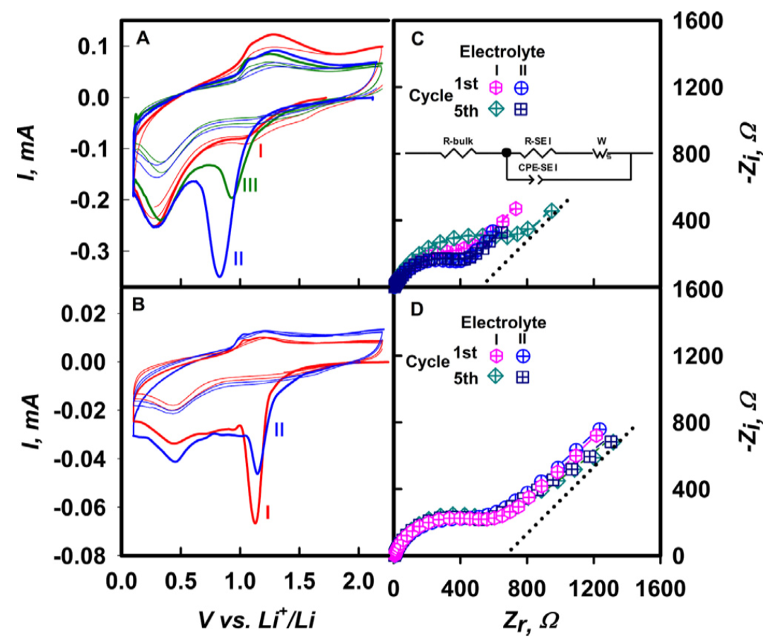
The CV diagrams for the symmetric cells of electrolytes given in Table 1 with two scanning rates are shown in Figure 2. We chose because it is a stable, weakly coordinating anion [22] and because it is shown to improve the electropolymerization morphology [23] and PC is widely used as a base solvent [24, 25]. In figure 2A and 2B, peaks between and correspond to PC reduction (PCR hereafter) [26]. Peaks at are assigned to the underpotential deposition (UPD) of on the basis of reported similar peaks within [27], and the fact that the peak at 1.3 V associated with the anodic stripping of UPD deposits does not appear following cathodic scans that were reversed at 0.9 V to avoid deposition.
4 Electrochemical Impedance Spectroscopy
The electrical characteristics of the SEI produced can be analyzed by electrochemical impedance spectroscopy (EIS). The EIS measurements can be performed at open circuit voltage (OCV). Therefore they only provide information about the static electrical properties of preformed SEI. A typical diagrams consist of a single depressed semicircle at medium and high frequencies, which merges at low frequencies into a straight line associated with diffusion through SEI layers. The presence of a single semicircle excludes significant contributions from multiple SEI layers. Thus SEI properties can be accounted by a single layer despite their complex, heterogeneous morphology and chemical composition . In the equivalent circuit shown in the diagram is the sum of ohmic drops across the electrolyte and other cell components, and are the resistance and capacitance of preformed SEI layers, and is the impedance arising from diffusion through SEI layers [28].
| CV cycle | Electrolyte | R-Bulk () | R-SEI () | C-SEI () | n | () | () | |
|---|---|---|---|---|---|---|---|---|
| I | 4 | 543 | 1.3 | 0.74 | 2.1 | 0.62 | 3.0 | |
| II | 3.1 | 459 | 1.5 | 0.73 | 3.6 | 0.60 | 1.1 | |
| I | 4.7 | 846 | 1 | 0.76 | 2.1 | 0.67 | 2.9 | |
| II | 3 | 489 | 1.6 | 0.72 | 3.9 | 0.62 | 0.9 |
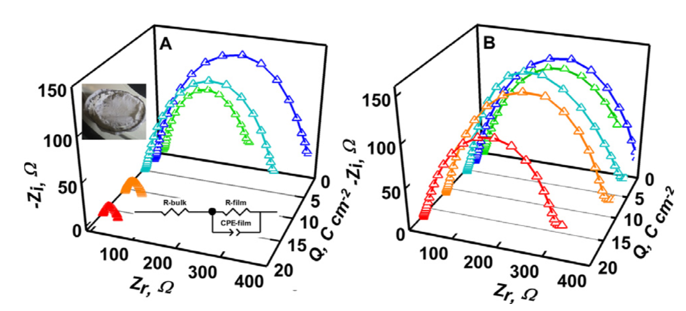
The implication is that the SEI production is followed by homogeneous chemical reactions that incorporate substantial amounts of additional PC into the layers. Constant phase element vs plots:
| (1) |
where is the real impedance, is a constant, is frequency, and and are adjustable parameters for Warburg’s impedance associated with diffusion in semi-infinite, homogeneous SEI layers. The morphology of SEI layers is evidently sensitive to scan and PCR rates. The kinetics of SEI formation. diffusion coefficient, in the SEI formed is obtained from
| (2) |
where is the gas constant, is absolute temperature (), is electrode area, is the ion charge, is Faraday’s constant, and is the slope of vs plots.
The resistance of SEI layers is directly proportional to thickness l, and electrical resistivity :
| (3) |
| CV cycle | Electrolyte | R-Bulk () | R-SEI () | C-SEI () | n | () | () | |
|---|---|---|---|---|---|---|---|---|
| I | 5.3 | 5439 | 2.7 | 0.79 | 3.2 | 0.50 | 1.3 | |
| II | 4.3 | 503 | 2.9 | 0.79 | 3.2 | 0.49 | 1.2 | |
| I | 4.7 | 543 | 3.1 | 0.82 | 3.0 | 0.46 | 1.5 | |
| II | 5.6 | 534 | 2.8 | 0.82 | 3.2 | 0.46 | 1.3 |
In contrast, the Nyquist diagrams of SEI grown at (Figure 2D) are qualitatively and quantitatively different from those in Figure 2C. In this case, the SEI produced from electrolytes I and II after the 1st and 5th scans have essentially identical parameters (Table 2), which are consistent with electronically insulating and PC-impermeable SEI layers. The presence of fluoride has a significant effect on the long-term stability of electropolymerization upon galvanostatic charging at . Note that and are simultaneously reduced during galvanostatic charging. Figures 2A and 2B show the evolution of Nyquist diagrams as functions of circulated charge. Noteworthy is the fact that the resistance of cells filled with II (containing ) decreases by only 25% after the circulation of , whereas the resistance of cells filled with I (without ) already drops eightfold at , as an indication that dendrites had pierced SEI layers, reached the cathode and short-circuited the cell. Fluoride additions also enhance the persistence of electropolymerization.
5 Chronoamperometry
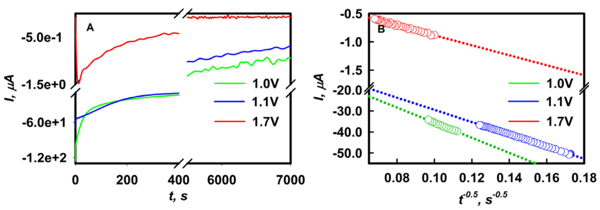
PCR at slow scan rates generates PC-impermeable SEI layers (Figures 2C and 2D) led us to test the dependence of PCR rates on applied potential by growing SEI under potentiostatic conditions. CA experiment at 1.0 , 1.1 and 1.7 V (vs )) applied potentials in cells filled with electrolyte I are shown in Fig. 4A. Faradaic currents associated with PCR (i.e., those circulating after the decay of initial capacitive currents) markedly increase at more negative overpotentials: (PCR rates peak at , Fig. 4B), as expected. This confirms that PCR rates lead to self-healing SEI layers, currents circulating in the CA at a underpotential vanish after , in contrast with experiments carried at and . Past the initial stages where currents are partially due to the capacitive charging of double layers (and also at , partially controlled by PC desolvation, cf. Fig. 2A and 2B), the slopes of faradaic currents vs :
| (4) |
| V (vs ) | Electrolyte | () | () | () | n | () | () | |
|---|---|---|---|---|---|---|---|---|
| 1.0 | 1st | 30 | 800 | 0.89 | 0.77 | 0.35 | 0.85 | 110 |
| 2nd | 35 | 1641 | 0.77 | 0.72 | 0.34 | 0.90 | 120 | |
| 1.1 | 1st | 14 | 920 | 0.95 | 0.73 | 0.79 | 0.78 | 21 |
| 2nd | 15 | 1336 | 0.72 | 0.73 | 0.71 | 0.77 | 26 | |
| 1.7 | 1st | 16 | 616 | 1.8 | 0.79 | 1.4 | 0.73 | 7.3 |
| 2nd | 16 | 565 | 1.6 | 0.80 | 2.0 | 0.71 | 3.4 |
lead to vastly different PC diffusion coefficients in SEI layers grown at 1.0 V: vs. those grown at 1.7 V: , which are compatible with the to values reported in porous and compact SEI layers, respectively [29]. Note that Eq. 4 for PC diffusion through a growing solid SEI layer is the analogue of Cottrell’s equation for ion diffusion through a widening, solvent-filled double layer. In both cases layer thicknesses increase with , and the corresponding current densities decrease with [28]. Most remarkably, is times smaller than through SEI layers that were seeded by a small fraction of the charge: ()
The relevant electrochemical characteristics of the SEI layers grown potentiostatically were probed by EIS and CV experiments. Nyquist diagrams of the SEI layers produced in successive chronoamperometry experiments under 1.0, 1.1 and 1.7 applied potentials are shown in Fig. 4A. The parameters derived from their analysis are compiled in Table 4. It is apparent that the SEI produced in the first 1.7 V potentiostatic experiment does not grow upon further charging, in contrast with those produced at 1.0 and 1.1 V. This conclusion is corroborated by CV scans (Fig. 4B).
Inspection of Table 4 reveals that:
-
1.
of the layers grown in initial cycles is comparable values despite the fact that the amount of PC reduced from electrolyte. remains nearly constant in 1.7 V experiments but increases by a factor of 2 in the second CA at 1.0 V.
-
2.
at 1.7 V is about times larger than those at 1.0 and 1.1 V suggesting (since ) that they are about half as thick.
-
3.
diffusion, with , is anomalous in all cases. Noteworthy is that for SEI layers produced at 1.7 V is comparable to the values in the SEI obtained in potentiodynamic CV experiments (see Tables 2 and 3), but much smaller than in SEI layers produced at 1.0 Li and 1.1 V, as evidence that SEI morphology is a sensitive function of applied potentials.
Summing up, the above findings are consistent with:
-
1.
SEI layers that incorporate PC molecules in larger numbers than those undergoing reduction at the electrode surface, i.e., SEI are essentially polymer materials [30].
-
2.
SEI properties strongly depend on the kinetics of the generation process. [31]
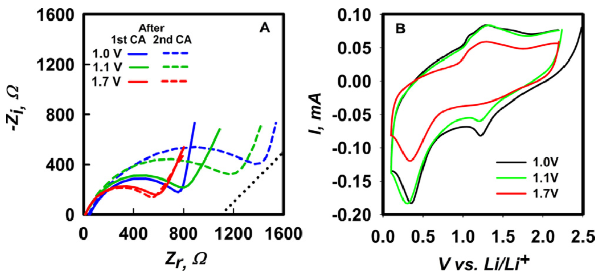
Figure 5: A: Nyquist diagrams at open circuit voltage of Cu|electrolyte|Li cells filled with electrolyte I after the first and second chronoamperometries at 1.0 V, 1.1 V and 1.7 V applied voltages vs. 1 M in PC. Dotted line: Warburg’s slope as a reference. B: CV at in cells with electrolyte I after being charged potentiostatically at 1.0 V, 1.1 V and 1.7 V for 2 h.[4]
Since SEI behave as polymeric materials, our findings suggest that the potential impact of experimental conditions on their properties should be evaluated on the basis of polymer science concepts [32, 33]. The radical chain PC electropolymerization into polymer units whose complexity increases at lower initiation rates. We show that slow initiation rates via one-electron PC reduction at underpotentials consistently yields compact, electronically insulating, Li+-conducting, PC- impermeable SEI films.What to expect for SEI generated in a polymerization process initiated by PC reduction, reaction eq:PC: [34, 35]
| (5) |
Following previous reports [30, 36], PC is deemed to open its ring into an alkoxycarbonyl radical followed by decomposition into or , plus simpler radical anions, , which initiates radical chain-growth polymerizations propagated by reactions 6:
| (6) |
| (7) |
SEI permeability, ionic and electronic conductivity, solubility and mechanical properties are essentially determined by the degree of solvent polymerization , i.e., by the number of monomers incorporated into polymer units [36]. is controlled by the competition between radical propagation (Reaction 6) vs. radical termination (Reaction 7). Thus we arrive at Reaction 8:
| (8) |
where are bimolecular reaction rate constants. Because initiation rates and termination rates balance at steady state, we have:
| (9) |
Therefore we arrive at Reaction 10:
| (10) |
which predicts that the degree of polymerization should be directly proportional to PC concentration at the front of advancing radical chains, and inversely proportional to (initiation rates: ). The fundamental relationship for a radical chain polymerization should apply whether are present in the SEI, as in the present case, or not.
Thus, our CA experiments at 1.7 V are deemed to produce functional SEI layers because the low current densities exclusively associated with PC reduction provide the slow initiation rates required to generate long polymerization chains. Furthermore, as a result, the overall slow polymerization process they bring about may not be limited by the availability of the free PC monomers released from the slow desolvation of . The very low value of the PC diffusion coefficient determined in the SEI generated at underpotential is clearly consistent with transport through a compact material comprising few, long and possibly linked or intertwined polymer chains [29]. From this perspective, the PC reduction rates at the overpotentials prevailing under conventional LMB charging conditions, where the full voltage required to plate the anode is applied from the onset, may not be ideal because they are likely to generate short, disjoint polymer domains rather than compact, interconnected polymer films extending over the electrode surface. We believe that our results and analysis provide new insights into the outstanding questions formulated in a recent review on the subject: ‘how does SEI form?’ and ‘what parameters control SEI properties?’ [37].
6 Experimental
Experiments were performed in two types of electrochemical cells filled with electrolyte solutions I, II and III of three different compositions (Table 1). Studies on SEI layers were carried out in coin cells whereas the deposition of films was investigated in coin cells. Round disk electrodes () were punched from foil (Aldrich, 99.9%, thick) that had been polished by scraping with a blade and rinsed with dimethyl carbonate. Electrodes were mounted on a transparent poly-methyl methacrylate separator that kept them apart. All operations were carried out in a glove box sparged with argon. Chronoamperometry (CA), electrochemical impedance spectroscopy (EIS) and cyclic voltammetry (CV) measurements were made with a Bio-Logic VSP potentiostat. Galvanostatic experiments were performed with an ARBIN BT2000 battery tester. EIS experiments ( modulation signal amplitude) covered the to frequency range. Impedance data were analyzed using Zview software. All reported potentials are relative to under working conditions. and foils (Sigma-Aldrich) were used as-received. Lithium per- chlorate (, Aldrich, battery grade, ) and lithium fluoride (, Aldrich, trace metal basis) were dried at under vacuum for and dissolved in propylene carbonate (PC) (Aldrich, 99.7% anhydrous). Further details can be found in previous publications from our laboratory. [7, 8, 38, 39]
Acknowledgement
Authors would like to thank Prof. William Goddard 222Chemistry and Chemical Engineering, California Institute of Technology, Pasadena, CA 91125; and Prof. Jaime Marian333Material Science and Engineering, University of California, Los Angeles, CA 90095; for their insightful comments in various instances.
References
- [1] Emanuel Peled. The electrochemical behavior of alkali and alkaline earth metals in nonaqueous battery systems, the solid electrolyte interphase model. Journal of The Electrochemical Society, 126(12):2047–2051, 1979.
- [2] Lars P Block. A double layer review. Astrophysics and Space Science, 55(1):59–83, 1978.
- [3] Xin-Bing Cheng, Rui Zhang, Chen-Zi Zhao, Fei Wei, Ji-Guang Zhang, and Qiang Zhang. A review of solid electrolyte interphases on lithium metal anode. Advanced Science, 3(3):1500213, 2016.
- [4] Laleh Majari Kasmaee, Asghar Aryanfar, Zarui Chikneyan, Michael R Hoffmann, and AgustÃn J Colussi. Lithium batteries: Improving solid-electrolyte interphases via underpotential solvent electropolymerization. Chemical Physics Letters, 661:65–69, 2016.
- [5] D. Aurbach. Review of selected electrode-solution interactions which determine the performance of li and li ion batteries. Journal of Power Sources, 89(2):206–218, 2000.
- [6] M Rosa Palacín and Anne de Guibert. Why do batteries fail? Science, 351(6273):1253292, 2016.
- [7] Asghar Aryanfar, Daniel Brooks, Boris V. Merinov, William A. Goddard Iii, AgustÃn J. Colussi, and Michael R. Hoffmann. Dynamics of lithium dendrite growth and inhibition: Pulse charging experiments and monte carlo calculations. The Journal of Physical Chemistry Letters, 5(10):1721–1726, 2014.
- [8] Asghar Aryanfar, Tao Cheng, Agustin J Colussi, Boris V Merinov, William A Goddard III, and Michael R Hoffmann. Annealing kinetics of electrodeposited lithium dendrites. The Journal of chemical physics, 143(13):134701, 2015.
- [9] Qing Chen, Ke Geng, and Karl Sieradzki. Prospects for dendrite-free cycling of li metal batteries. Journal of The Electrochemical Society, 162(10):A2004–A2007, 2015.
- [10] Yaohui Zhang, Jiangfeng Qian, Wu Xu, Selena M Russell, Xilin Chen, Eduard Nasybulin, Priyanka Bhattacharya, Mark H Engelhard, Donghai Mei, Ruiguo Cao, et al. Dendrite-free lithium deposition with self-aligned nanorod structure. Nano letters, 14(12):6889–6896, 2014.
- [11] Fernando A Soto, Yuguang Ma, Julibeth M Martinez de la Hoz, Jorge M Seminario, and Perla B Balbuena. Formation and growth mechanisms of solid-electrolyte interphase layers in rechargeable batteries. Chemistry of Materials, 27(23):7990–8000, 2015.
- [12] Seong Jin An, Jianlin Li, Claus Daniel, Debasish Mohanty, Shrikant Nagpure, and David L Wood III. The state of understanding of the lithium-ion-battery graphite solid electrolyte interphase (sei) and its relationship to formation cycling. Carbon, 105:52–76, 2016.
- [13] Victor A Agubra and Jeffrey W Fergus. The formation and stability of the solid electrolyte interface on the graphite anode. Journal of Power Sources, 268:153–162, 2014.
- [14] Frederic Blanc, Michal Leskes, and Clare P Grey. In situ solid-state nmr spectroscopy of electrochemical cells: batteries, supercapacitors, and fuel cells. Accounts of chemical research, 46(9):1952–1963, 2013.
- [15] Simon F Lux, Ivan T Lucas, Julie S Chevalier, Thomas J Richardson, and Robert M Kostecki. Time-dependent determination of hf formation in lipf6-containing electrolytes in different cell types by spectroscopic ellipsometry. ECS Transactions, 50(1):27–30, 2013.
- [16] Le Yu, Huijin Liu, Yan Wang, Naoaki Kuwata, Masatoshi Osawa, Junichi Kawamura, and Shen Ye. Preferential adsorption of solvents on the cathode surface of lithium ion batteries. Angewandte Chemie, 125(22):5865–5868, 2013.
- [17] Zhe Li, Jun Huang, Bor Yann Liaw, Viktor Metzler, and Jianbo Zhang. A review of lithium deposition in lithium-ion and lithium metal secondary batteries. Journal of Power Sources, 254:168–182, 2014.
- [18] Craig A Bridges, Xiao-Guang Sun, Jinkui Zhao, M Parans Paranthaman, and Sheng Dai. In situ observation of solid electrolyte interphase formation in ordered mesoporous hard carbon by small-angle neutron scattering. The Journal of Physical Chemistry C, 116(14):7701–7711, 2012.
- [19] Yingying Lu, Zhengyuan Tu, and Lynden A. Archer. Stable lithium electrodeposition in liquid and nanoporous solid electrolytes. Nat Mater, 13(10):961–969, 2014.
- [20] W. Xu, J. L. Wang, F. Ding, X. L. Chen, E. Nasybutin, Y. H. Zhang, and J. G. Zhang. Lithium metal anodes for rechargeable batteries. Energy and Environmental Science, 7(2):513–537, 2014.
- [21] Tetsuya Osaka, Katsuhiko Naoi, Satoshi Ogano, and Sadako Nakamura. Dependence of film thickness on electrochemical kinetics of polypyrrole and on properties of lithium/polypyrrole battery. Journal of The Electrochemical Society, 134(9):2096–2102, 1987.
- [22] Vincenzo Mauro, Alessandro DAprano, Fausto Croce, and Mark Salomon. Direct determination of transference numbers of liclo4 solutions in propylene carbonate and acetonitrile. Journal of power sources, 141(1):167–170, 2005.
- [23] Snehashis Choudhury and Lynden A Archer. Lithium fluoride additives for stable cycling of lithium batteries at high current densities. Advanced Electronic Materials, 2(2):1500246, 2016.
- [24] Mengyun Nie, Julien Demeaux, Benjamin T Young, David R Heskett, Yanjing Chen, Arijit Bose, Joseph C Woicik, and Brett L Lucht. Effect of vinylene carbonate and fluoroethylene carbonate on sei formation on graphitic anodes in li-ion batteries. Journal of The Electrochemical Society, 162(13):A7008–A7014, 2015.
- [25] Irina A Profatilova, Christoph Stock, André Schmitz, Stefano Passerini, and Martin Winter. Enhanced thermal stability of a lithiated nano-silicon electrode by fluoroethylene carbonate and vinylene carbonate. Journal of Power Sources, 222:140–149, 2013.
- [26] Benjamin Schaffner, Friederike Schaffner, Sergey P Verevkin, and Armin Borner. Organic carbonates as solvents in synthesis and catalysis. Chemical reviews, 110(8):4554–4581, 2010.
- [27] Toshiya Saito and Kohei Uosaki. Surface film formation and lithium underpotential deposition on au (111) surfaces in propylene carbonate in situ scanning tunneling microscopy study. Journal of The Electrochemical Society, 150(4):A532–A537, 2003.
- [28] Allen J. Bard and Larry R. Faulkner. Electrochemical methods: fundamentals and applications. 2 New York: Wiley, 1980., 1980.
- [29] Pengjian Guan, Lin Liu, and Xianke Lin. Simulation and experiment on solid electrolyte interphase (sei) morphology evolution and lithium-ion diffusion. Journal of The Electrochemical Society, 162(9):A1798–A1808, 2015.
- [30] Hadi Tavassol, Joseph W Buthker, Glen A Ferguson, Larry A Curtiss, and Andrew A Gewirth. Solvent oligomerization during sei formation on model systems for li-ion battery anodes. Journal of The Electrochemical Society, 159(6):A730–A738, 2012.
- [31] Jeong Yoon Koh and Yongju Jung. Nanoscale morphology control of conducting polymers by cathodic polymerization route. Int. J. Electrochem. Sci, 8(7):10080–10085, 2013.
- [32] PJ Flory et al. Principles of polymer chemistry ithaca. NY: Cornell University, 1953.
- [33] Serge Cosnier and Arkady Karyakin. Electropolymerization: concepts, materials and applications. John Wiley & Sons, 2011.
- [34] Daniel M Seo, Dinesh Chalasani, Bharathy S Parimalam, Rahul Kadam, Mengyun Nie, and Brett L Lucht. Reduction reactions of carbonate solvents for lithium ion batteries. ECS Electrochemistry Letters, 3(9):A91–A93, 2014.
- [35] Gregory Gachot, Sylvie Grugeon, Michel Armand, Serge Pilard, Pierre Guenot, Jean-Marie Tarascon, and Stephane Laruelle. Deciphering the multi-step degradation mechanisms of carbonate-based electrolyte in li batteries. Journal of Power Sources, 178(1):409–421, 2008.
- [36] Ilya A Shkrob, Ye Zhu, Timothy W Marin, and Daniel Abraham. Reduction of carbonate electrolytes and the formation of solid-electrolyte interface (sei) in lithium-ion batteries. 1. spectroscopic observations of radical intermediates generated in one-electron reduction of carbonates. The Journal of Physical Chemistry C, 117(38):19255–19269, 2013.
- [37] Magali Gauthier, Thomas J Carney, Alexis Grimaud, Livia Giordano, Nir Pour, Hao-Hsun Chang, David P Fenning, Simon F Lux, Odysseas Paschos, Christoph Bauer, et al. Electrode–electrolyte interface in li-ion batteries: Current understanding and new insights. The journal of physical chemistry letters, 6(22):4653–4672, 2015.
- [38] Asghar Aryanfar, Daniel J Brooks, AgustÃn J Colussi, Boris V Merinov, William A Goddard III, and Michael R Hoffmann. Thermal relaxation of lithium dendrites. Physical Chemistry Chemical Physics, 17(12):8000–8005, 2015.
- [39] Asghar Aryanfar, Daniel J Brooks, Agustin J Colussi, and Michael R Hoffmann. Quantifying the dependence of dead lithium losses on the cycling period in lithium metal batteries. Physical Chemistry Chemical Physics, 16(45):24965–24970, 2014.