Geometry-induced interface pinning at completely wet walls
Abstract
We study complete wetting of solid walls that are patterned by parallel nanogrooves of depth and width with a periodicity of . The wall is formed of a material which interacts with the fluid via a long-range potential and exhibits first-order wetting transition at temperature , should the wall is planar. Using a non-local density functional theory we show that at a fixed temperature the process of complete wetting depends sensitively on two microscopic length-scales and . If the corrugation parameter is greater than , the process is continuous similar to complete wetting on a planar wall. For , the complete wetting exhibits first-order depinning transition corresponding to an abrupt unbinding of the liquid-gas interface from the wall. Finally, for the interface remains pinned at the wall even at bulk liquid-gas coexistence. This implies that nano-modification of substrate surfaces can always change their wetting character from hydrophilic into hydrophobic, in direct contrast to the macroscopic Wenzel law. The resulting surface phase diagram reveals close analogy between the depinning and prewetting transitions including the nature of their critical points.
The recent advances in nanophysics have not only revealed promising possibilities in modern technologies but also induced new theoretical challenges. This includes a particularly important problem that has attracted enormous interest across different scientific branches and which can be formulated as follows: what is the effect of a solid surface structure on its wetting properties? On a macroscopic level, the influence of a non-planar structure on adsorption behaviour of the substrate can be described by Wenzel’s law wenzel36
| (1) |
which relates Young’s contact angle of a liquid droplet on a planar surface with an apparent contact angle of a liquid droplet on a structured surface. Since the roughness parameter , Eq. (1) implies that if and if meaning that the wetting/drying properties are amplified by the surface structure.
Nevertheless, it turns out that the behaviour of fluids adsorbed at rough substrates is, at a minimum, much more complex netz ; chow ; swain ; quere1 ; quere2 ; herminghaus_rev ; erbil ; krasimir , especially upon decreasing the length-scale characterizing structure of the solid surface fox ; ruckenstein ; rauscher ; gross ; herminghaus ; dutka ; malanoski . Further aspects, such that the surface geometry, the nature of microscopic forces, line tension contribution, strong packing effects that fluid molecules experience near the wall etc., are all ignored in the phenomenological Wenzel law, yet they are crucial for obtaining the full picture. In particular, it has been recognized that interfacial phenomena occurring on structured substrates depend on the nature of wetting properties of the pertinent planar substrate santori ; rascon ; rejmer0 ; kubalski ; rejmer02 ; rejmer07 ; silvestre ; rodriguez : If the planar substrate experiences continuous (critical) wetting transition dietrich ; schick ; bonn at temperature (and at bulk liquid-gas coexistence) which corresponds to vanishing of the contact angle, , the corrugated substrate also exhibits continuous wetting transition at the same temperature. The character of the wetting transition is also unchanged if the planar substrate exhibits first-order wetting but in this case the wetting temperature of the corrugated substrate is shifted towards lower values, qualitatively in line with Eq. (1) rascon ; kubalski ; rejmer02 . Moreover, the wetting can be preceded by unbending (or filling) transition corresponding to an abrupt condensation of the fluid inside the wall troughs, provided the corrugation amplitude is sufficiently large.
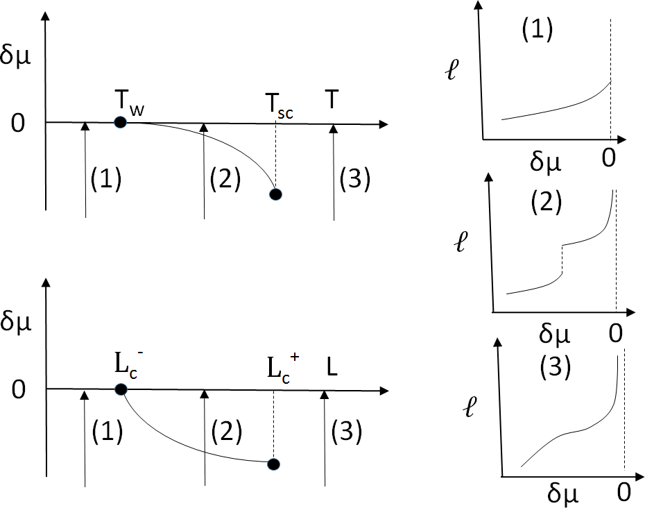
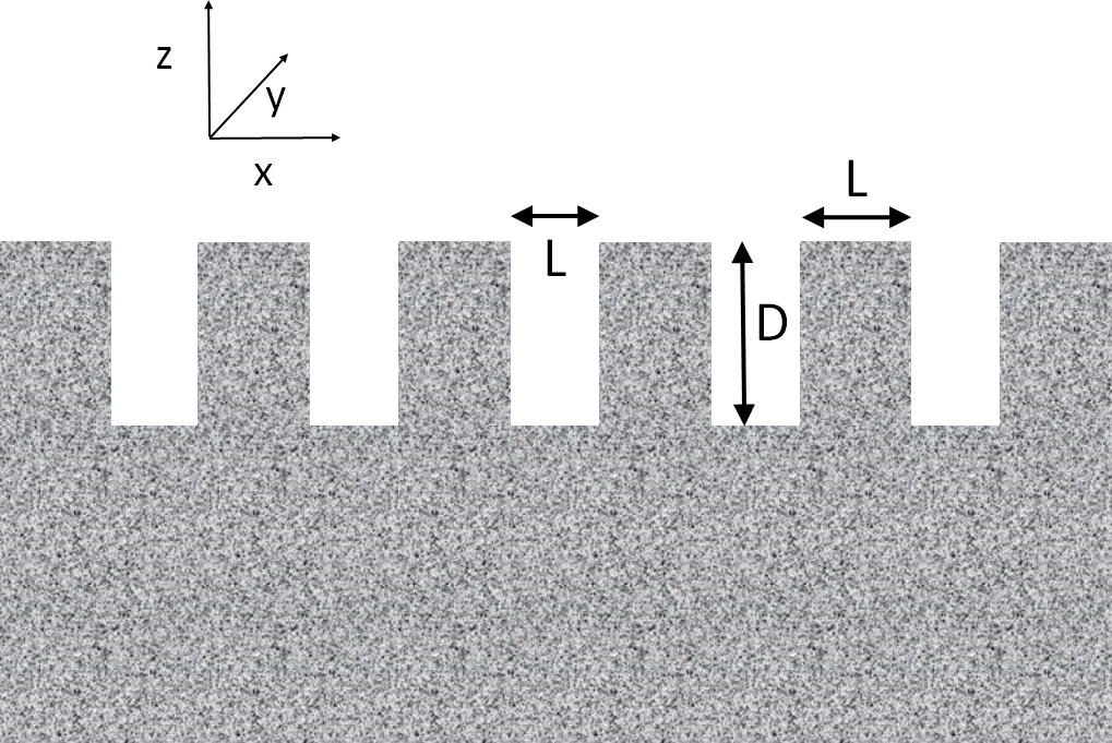
These predictions are based on a mesoscopic analysis of the liquid-gas interface interacting with the solid wall according to an effective (binding) potential dietrich . However, if the substrate structure is microscopic, i.e. on the scale of molecular diameters, a more detailed treatment of an adsorbed fluid is needed. In this work, we consider a model substrate formed by a solid planar wall into which a one-dimensional array of rectangular grooves of depth and width is etched with a periodicity . The groove parameters and are deemed to be microscopically small, while the length of the grooves along the remaining Cartesian axis is assumed to be macroscopically long, so that the wall corrugation breaks the translation symmetry of the system only in one direction (cf. Fig. 1). The wall is at contact with a bulk gas at a (subcritical) temperature and the chemical potential , where is the wetting temperature at which first-order wetting transition occurs at the corresponding planar wall and is the chemical potential at bulk liquid-gas coexistence. For planar walls the process is known as complete wetting and can be characterized by a an unbinding of the liquid-gas interface mean height which eventually diverges according to the power-law where and the critical exponent for systems with long-ranged (dispersion) forces dietrich ; schick ; bonn . We also recall that for first-order wetting the singular behaviour of the surface free energy at extends to and below , giving rise to a finite jump in ; this prewetting transition terminates at the surface critical point . Schematically, the surface phase diagram for complete wetting at a planar wall is displayed in Fig. 2, together with three illustrative adsorption isotherms. Here we also show the - phase diagram corresponding to our model substrate which summarizes the main results of this work. It demonstrates three possible adsorption scenarios, depending on : i) the adsorption is continuous similar to complete wetting on a planar wall if the corrugation parameter is greater than a certain critical value ; ii) for below but above the adsorption exhibits first-order depinning transition at some value corresponding to an abrupt depinning of the interface from the wall followed by a continuous divergence of the interface height as ; iii) finally, for the interface remains pinned at the wall even at preventing complete wetting despite Young’s contact angle .
We have obtained our results using a microscopic density functional theory (DFT) evans79 , which has proven to be an extraordinary useful tool for a description of structure and phase behaviour of inhomogeneous fluids evans16 . All the information about the given model fluid properties is embraced in the intrinsic free energy functional of the local one-body fluid density which, for simple fluids, can be decomposed in a perturbative manner as follows:
| (2) |
Here, is the kinetic (ideal gas) contribution to the free energy where is the inverse temperature and is the thermal de Broglie wavelength. The excess part of the free energy functional due to the fluid-fluid interactions is further separated to the repulsive portion , which is mapped onto a system of hard spheres with a diameter within the non-local Rosenfeld fundamental-measure-theory functional ros , and the attractive part which we treat in the mean-field manner . For the attractive part of the fluid-fluid interaction, , we have chosen the truncated and non-shifted Lennard-Jones-like potential
| (3) |
where the parameters and are used as the energy and length-scale units, respectively, and where the potential cut-off is set to . The microscopic model accounts accurately for the short-ranged fluid correlations (and thus the packing effects) and satisfies exact statistical mechanical sum rules hend92 . The confining wall (illustrated in Fig. 1), steps into the theory within the external potential which is obtained by integrating the wall-fluid atom-atom interactions over the whole volume of the wall. With the wall atoms assumed to be distributed uniformly with a density and interacting with the fluid atoms via the Lennard-Jones (LJ) potential , the wall potential can be expressed as
| (4) |
except for the region corresponding to the domain of the wall in which case as the wall is impenetrable. The potential of a single pillar of height and width can be split into the repulsive and attractive contributions where
| (5) | |||||
and
| (6) | |||||
with
| (7) |
and
| (8) |
Finally, the potential in (4) is the standard - LJ potential induced by a planar wall spanning the volume .

The equilibrium density profile is obtained by minimizing the grand potential functional
| (9) |
which is solved iteratively on a two-dimensional grid with a uniform spacing of . The minimization determines the equilibrium density profile and also the thermodynamic grand potential . Having set the wall parameter we find the wetting temperature of the planar wall , where is the bulk critical temperature of the fluid.
In Fig. 3 we display the surface phase diagram in the - projection obtained from the DFT for and the grooves depth . The phase diagram shows the line corresponding to first-order depinning transition at which the grand potentials obtained by minimizing of (9) for the pinned (low adsorption) and depinned (high adsorption) states are equal. The line connects the (horizontal) bulk coexistence line at meaning that below this threshold the wall structure prevents complete wetting. The depinning line terminates at the critical point above which the depinning is continuous. For , a unique solution for the density profile is always obtained regardless of the initial state which the minimization of (9) starts from. However, below , the function exhibits two local minima within the interval constrained by the spinodal lines which are also shown in Fig. 3. Therefore, this interval indicates a range of metastable extensions of either solution characteristic to first-order transitions. The spinodals display the loci where one of the two minima in vanishes and becomes an inflection (cf. Fig. 6 below), i.e. the limit of stability of the corresponding (pinned or depinned) configuration.
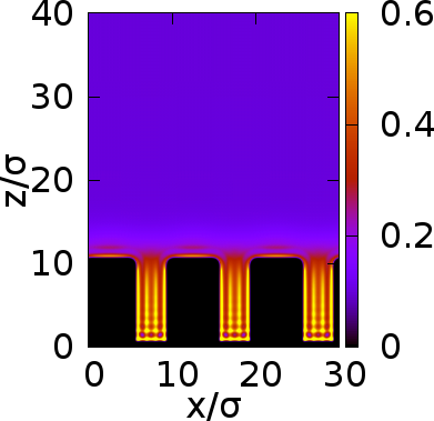
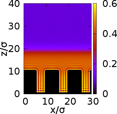
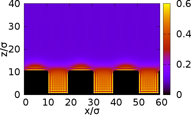
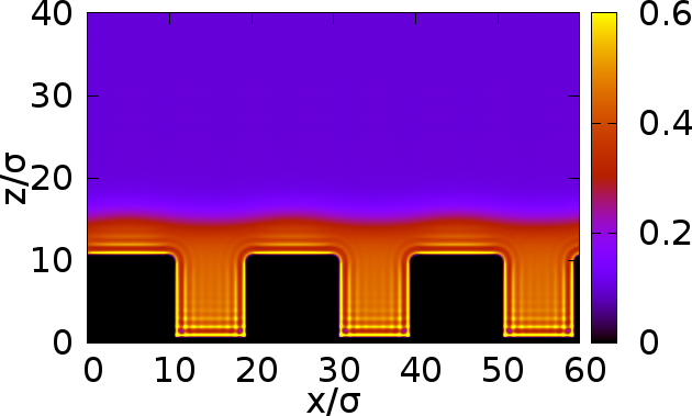
To illustrate the change in the structure of the fluid at the depinning transition we show in Fig. 4 density profiles (over three periods) corresponding to coexisting pinned and depinned states for and . The two examples differ rather remarkably; for low , the depinned state possesses a thick wetting layer with essentially flat interface, while the upper part of the wall is only microscopically wet in the pinned state. For large , the width of the wetting film after the transition is substantially smaller and exhibits distinct periodic corrugation of the liquid-gas interface which follows closely the lateral inhomogeneity in the wall potential. Before the transition, liquid droplets that are pinned at the wall edges are now present, as the width of the pillars is large enough to accommodate them. One should also notice the strongly inhomogeneous fluid structure in the grooves showing pronounced layering that get connected at the depinned states; this suggests that the transition can also be viewed as bridging of the condensed phase filling the grooves.
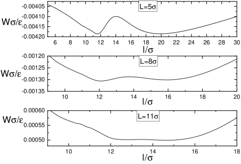
Some more details about the depinning transition can be obtained by constructing the binding potential , i.e. the constrained free energy per unit length at the fixed mean height of the adsorbed film (from the grooves bottom), , so that the mean-field equilibrium state is given by the global minimum of . For this, we minimize the grand potential (9) as a subject of fixed adsorption bind where is the bulk fluid density. In Fig. 5 we display the binding potentials corresponding to the three points laying on the depinning line as depicted in Fig. 3. For the lowest value of , the binding potential possesses two distinct local minima of the same depths that are separated by a well pronounced free-energy barrier. On increasing , i.e. by approaching , the free-energy barrier is lowered, as well as the gap between the two minima which eventually merge at the critical point. Clearly, this is only the second minimum of the position of which depends on , with the first minimum being always located near corresponding to the grooves top.
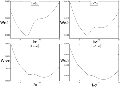
In Fig. 6 we also show the binding potentials for the points away of the depinning transition at the fixed chemical potential. The effect of varying is now different; namely it determines the depths of the two competing free-energy minima but their locations remain unchanged within the whole interval of between the spinodal points (cf. Fig. 3) beyond which only one local minimum in exists. This can be explained as follows. Within the sharp-kink approximation dietrich , the binding potential of the system in the depinned state can be written as
| (10) |
Here, the first term on the right hand side is the free-energy cost for the presence of the metastable liquid (ignoring the constant contribution due to the filled grooves) and the remaining terms account for the local effective interaction between the wall and the liquid-gas interface which is considered to be flat. This interaction is approximated by a simple quadratic power-law in the inverse height of the interface with the amplitude (Hamaker constant) , where is the difference between the bulk coexisting densities. Therefore, within the approximation scales linearly with and hence the interface height is -independent, in line with the DFT results. It should be emphasized that the model (10) is only applicable to the depinned state (and is meaningful only above the lower spinodal of the phase diagram) and has no relevance to the nature of the depinning transition. Indeed, the full model would rely on a definition of two distinct fluid configurations (pinned and depinned states) and would not thus be able to predict the presence of the critical point . However, Eq. (10) can be further used to find a correspondence between our substrate model involving grooves and a simple planar wall covered by a wetting film of width , for which the dominating contribution to the binding potential is
| (11) |
defined per unit area. The effective Hamaker constant of the planar wall is determined by equating the heights of the wetting films at the corresponding substrates, , obtained by minimization of (10) and (11), respectively. This leads to the condition
| (12) |
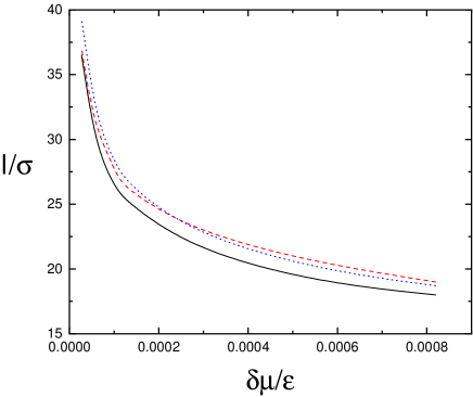
for as a function of the scaling parameter , which eventually yields . It can be checked easily, that for and for , as expected covar . Using DFT, we test this result by comparing the height of the depinned interface at the structured wall with and and the potential strength , with that corresponding to the planar wall with the potential strength as obtained from Eq. (12). The comparison shown in Fig. 7 reveals that the two solutions, and , are fairly close to each other, although the interface height above the planar wall is systematically slightly larger. For completeness, we also plot as obtained directly from Eq. (12) which almost follows ; the upshot is that while the asymptotic form of the planar binding potential (11) works very accurately within the displayed interval, the binding potential for the structured wall (10) provides still a reasonable approximation.
In summary, we have studied adsorption of a solid wall structured by a linear array of parallel rectangular grooves above the wetting temperature, so that Young’s contact angle of the wall is zero. We have found that the presence of the wall structure does not qualitatively change the process of complete wetting unless the characteristic length of the wall structure is microscopically small. In this case, the mechanism of complete wetting is via bridging of liquid layers inside the grooves over the top of the wall. The corresponding free energy change involves a contribution associated with the line tension pertinent to a contact of the liquid-gas interface with the wall edges. This term competes within the excess free energy with the surface tension effects as and is thus increasingly relevant as decreases. Its role becomes dominant for such that the free energy barrier cannot be overcome even at the bulk coexistence and the bridging and complete wetting of the wall is thus not possible. However, as our DFT calculations show, this is only in the case when is less than about four molecular diameters (). For larger , the system experiences competition between two free energy minima giving rise to first-order depinning transition. The edge effects and hence the transition is gradually weaker as increases and eventually becomes continuous at ) where the barrier vanishes. For the shape of the interface changes smoothly all the way along its unbinding from the wall. The - phase diagram reveals some analogy between prewetting and depinning transitions, although the curvatures of the corresponding lines have opposite signs. This study can be extended in numerous ways. A natural generalization of our model would treat the grooves width and the periodicity as independent parameters; this, for example, would convert Eq. (12) simply into with but the phase behaviour at such a wall can be expected to be considerably more complicated. Further, here we have deliberately chosen a sufficiently high temperature in order to avoid prewetting at the wall; for one expects competition between depinning and prewetting. It would also be interesting to explore -dependence of the depinning phenomena and check possible scaling properties as in Eq. (12). Finally, it should be noted that in view of its pseudo-2D character and the presence of long-range forces, the depinning transition would not be rounded beyond the current mean-field analysis due to thermal fluctuations and should thus be accessible in real experiments.
Acknowledgements.
This work was financially supported by the Czech Science Foundation, Project No. GA17-25100S.References
- (1) R. N. Wenzel, Ind. Eng. Chem. 28, 988 (1936).
- (2) R. R. Netz and D. Andelman, Phys. Rev. E 55, 687 (1997).
- (3) T. S. Chow, J. Phys.: Condens. Matter 10, L445 (1998)
- (4) P. S. Swain and R. Lipowsky, Langmuir 14, 6772 (1998).
- (5) D. Quéré, Physica A 313, 32 (2002).
- (6) D. Quéré, Annu. Rev. Mater. Res. 38, 71 (2008).
- (7) S. Herminghaus, M. Brinkmann, R. Seemann, Annu. Rev. Mater. Res. 38, 101 (2008).
- (8) H. Y. Erbil, Surface Science Reports 69, 325 (2014).
- (9) M. N. MacGregor-Ramiasa and V. Krasimir, Adv. Mater. Interfaces 4, UNSP 1700381 (2017).
- (10) A. O. Parry, P.S. Swain, and J. A. Fox, J. Phys.: Condens. Matter 8, L659 (1996).
- (11) E. Ruckenstein and G. O. Berim, Adv. Colloid. Interface Sci. 157, 1 (2010); J. Chem. Phys. 129, 014708 (2008).
- (12) M. Rauscher and S. Dietrich, Annu. Rev. Mater. Res. 38, 143 (2008); Soft Matter 5, 2997 (2009).
- (13) M. Gross, F. Varnik, D. Raabe, and I. Steinbach, Phys. Rev. E 81, 051606 (2010).
- (14) S. Herminghaus, Phys. Rev. Lett. 109, 236102 (2012).
- (15) F. Dutka, M. Napiorkowski, and S. Dietrich, J. Chem. Phys. 136, 064702 (2012).
- (16) A. P. Malanoski, B. J. Johnson, and J. S. Erickson, Nanoscale 6, 5620 (2014).
- (17) C. Rascón, A. O. Parry, and A. Santori, Phys. Rev. E 59, 5697 (1999).
- (18) C. Rascón and A. O. Parry, J. Phys.: Condens. Matter 12, A369 (2000).
- (19) K. Rejmer and M. Napiórkowski, Phys. Rev. E 62, 588 (2000).
- (20) G. P. Kubalski, M. Napiórkowski, and K. Rejmer, J. Phys.: Condens. Matter 13, 4272 (2001).
- (21) K. Rejmer, Phys. Rev. E 65, 061606 (2002).
- (22) K. Rejmer, Physica A 373, 58 (2007).
- (23) N. M. Silvestre, Z. Eskandari, P. Patrício, J. M. Romero-Enrique, and M. M. Telo da Gama, Phys.Rev. E 86, 011703 (2012).
- (24) A. Rodriguez-Rivas, J. Galván, and J. M. Romero-Enrique, J. Phys. Condens. Matter 27, 035101 (2015).
- (25) S. Dietrich, in Phase Transitions and Critical Phenomena, edited by C. Domb and J. L. Lebowitz (Academic press, New York, 1988), Vol. 12.
- (26) M. Schick, in Liquids and Interfaces, edited by J. Chorvolin, J. F. Joanny, and J. Zinn-Justin (Elsevier, New York, 1990).
- (27) D. Bonn, J. Eggers, J. Indekeu, J. Meunier, and E. Rolley, Rev. Mod. Phys. 81 739, (2009).
- (28) R. Evans, Adv. Phys. 28, 143 (1979).
- (29) R. Evans, M. Oettel, R. Roth amd G. Kahl, J. Phys. Condens. Matter 28, 240401 (2016).
- (30) Y. Rosenfeld, Phys. Rev. Lett. 63, 980 (1989).
- (31) J. R. Henderson in Fundamentals of Inhomogeneous Fluids, New York: Dekker (ed. by D. Henderson), (1992).
- (32) A. Malijevský, J. Chem. Phys. 141, 184703 (2014). The mean height of the interface is defined as for and for , where .
- (33) If the correspondence is defined by a condition by considering the upper part of the structured wall as the reference level, the minus sign on the l.h.s. of Eq. (12) would change and this would also imply in the limit of .