Configuration-Space Flipper Planning for Rescue Robots
Abstract
For rescue robots, flipper endows the robot with additional ability to pass through various terrain. Autonomous motion becomes more important. In recent work autonomy is done by either planning with several special states or based on collected data. We are considering if it is possible to find a way to build continues states without collecting old trail data. In this paper, we first model the possible states as a global planning path with parameter configuration of the scene. Then, we follows the path to achieve the autonomous run. We plot the morphology of each path points to show the correctness of the path and implement a simple path following on real robot to demonstrate the performance of our algorithm.
I INTRODUCTION
In robotics, one of the most important mission is to mitigate after disaster happened. Robots have to possess various abilities to tackle the hostile environment. The RoboCup Rescue competition, that has been held 19 years since 2000, provides a stage to evaluate the potential of rescue robots. It aims at assessing the robot capabilities. Various arenas, such as Curb or Stair Debris were designed to test the maneuvering and mobility of the robots [1].
In RoboCup, most of the teams are using tracked vehicles. As discussed in [2], tracked robot has its own advantages. Comparing with wheeled robot, it has a larger ground contact surface. And tracked robot would be more stable for the lower center of gravity than bipeds.
For the maneuvering and mobility, it is a popular strategy to mount flippers on rescue robots to increase its ability to pass trough various terrain. The most commonly designs used in research consists of front (and back) subtracks mounted on the main body with rotary joints [3][2][4][5][6][7]. There are also people working with reconfigurable robots [8], transformable robots [9], four tracked robots [10] and others. Those more specially designed robot are not majorly involved in research, competition and product. In this work, we utilize our algorithm on the robot shown in Fig. 2, which is following the common flipper design principle.

However, the additional operation of the flippers increases the complexity in controlling the robot.
Tele-operating can be a choice to direct the robot moving. The problem is, when the communication quality can not be guaranteed, it is urgent to ensure the robot can run autonomously. Running autonomously is an important ability for rescue robots.
In this work, we focus on the algorithms to generating a global plan for tracked robots with flippers.
Tracked robots have been explored in many papers. [11] note the difficulty of climbing stairs for tracked robots for the limits on operator’s feedback. Then batches of works have attempted the tackle the stair climbing problem. [3] relies on sonar, monocular camera and two-axis accelerator, proposing a sensor fusion model. In [12], robot’s heading can be determined by only using monocular vision. After that, [2] propose an algorithm that can performing robustly in real world scenes without the pre-assumption of the stair geometry, interaction between wheel and stair surface or the light condition. Though, the planning of subtracks is not mentioned much in those work. It does not play out the potential of flippers. Actually, the flipper planning algorithms are either with state machine adopt the task with several simple morphology or data driven by pre-collecting trails. [13] group the configuration of flippers into four postures and make execution on its corresponding situation. [14] utilize reinforcement learning (RL) to accommodate the morphology to the terrain. Sequentially, [15] further enhance the capability of control with Relative Entropy Policy Search. Make effort on the observation, [6] model the incomplete measurement and make control on the robot morphology under RL. Similarly, [16] describe a detailed implemented framework to learn the mobility from simulation experiments using deep neural network. [17] learn the effect of action and make plan on reconfiguration of tracks to tackle various obstacles.
Our work is inspired by [17], that model the relation of angles for body and flipper with the extended qualitative model on climbing a step. Thus we are considering that it should be possible to model the scene and robot as a whole with parameters that are related to the obstacle. So in this paper, we model the step climbing for a tracked rescue robot with flippers as a global search, with each point in the path a possible morphology of the robot.
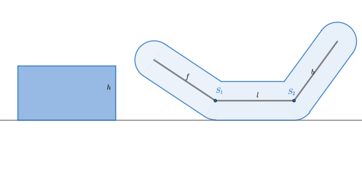
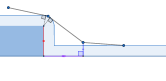
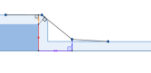
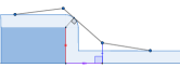
As in Fig. 1, suitable simplification is taken from robot-ground scene to skeleton-dilated ground scene. This simplification takes benefit of our robot design and will be discussed in the next section. Other similar robots can also use this method.
Next we present the interrelation with several configuration parameter, with various restrictions to constraint configuration to be a possible setting of robot on ground. In this way, we can collect the whole space of our parameters and make planning over it.
II Methodology
In this section, we will introduce our method in detail. It consist of simplification and representation, global planning and path following. Please note, our robot is standing straight to the step, that is, the initial orientation is perpendicular to the vertical plane of the step. While this is a great restriction of our algorithm, the experiments will show that our approach works well even when this condition is violated.
II-A Represent the Model with Parameters

This work is derived from our rescue robot shown in Fig. 2. Its side view is as in Fig. 1a. To make things clear, we draw lines to connect the neighbor motor joints and call those lines the skeleton. We observe that the closest distance from skeleton to track is always the wheel radius . Taking the advantage of our rescue robot design, we can simplify the robot as its skeleton while dilate the ground and obstacle with track radius as in Fig. 1b. We denote the front and back joints as and . The mobile base is line , the front and back flippers are line and , respectively. We also call the quarter circle as curve and it will be used in following parts.
Then we represent the possible states of the robot in the world with three parameters , and as plotted in Fig. 1b. Where is the horizontal distance from to the stair, is the vertical distance from to ground, is the angle between line and . We consider to be positive if is on the right side of ray and negative otherwise.
Please note that those three parameters are adequate to represent the state since the back flipper angle and angle of elevation can be uniquely determined given corresponding , and , which will be discussed in Section II-C.
II-B Global Planning for Rescue Robot
Actually, the main idea for our Global Planning is using a function to determine if one configuration is available and search in this possible space.
The whole algorithm is shown in Algorithm 1 and its detail are discussed in following subsection.
II-B1 State Check
State check is a function that can return the feasible alpha angles by feeding certain , pairs.
In our method, for safety, we assume there are some rules that the morphology should follow:
-
•
When the skeleton touches the curve part of surface and want to lift or , it should be tangent to the curve.
-
•
The base should either touch the ground on or be tangent to the curve part of surface.
The first rule ensures that the obstacle will not block the movement of the robot. The second rule constrained the morphology into feasible group that won’t slip down from step.
The main idea is that we can group morphologies into groups of states that are divided by several conditions. Then we treat each state separately. Those conditions are computed with and .
For each pair of , we can determine which group it belongs to. That is, we find the corresponding rough morphology for this pair. Then it will be easy to compute the valid range of to obtain the accurate morphology.
In this algorithm we traverse from larger value to smaller ones. As shown in Fig. 3, the d’s space is represented by an axis, where s are critical points and s are states between critical points. For each , we check its relation to in ascend order of to distribute it to corresponding state .
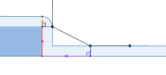
In our design, we want to ensure a stability of robot to avoid the morphology that is possible to slip down of the stairs as in Rule 1. So we pre-assume the flipper () should be tangent to the curve if leave the ground. The body () should be tangent to the curve if leave the ground.
From the beginning, is the critical point where . If the robot moves farther from the step (in state ) then , its flippers could be free within their bounded range. If it moves closer (in R2 to R10), the flippers’ movement will under some constrains, for example, the front flipper will be able to touch the step.
is the critical point where the front end() of the flipper just on the bottom end of the curve. If the robot is further, it will hold a minimum that will touch the vertical plane of the step (in state R2). If the robot moves little bit closer, will be possible to touch the curve (in state R3).
, as an important division, indicates that the further morphology should not lift the , since the front flipper is not tangent to the curve at all. As robot moves forward to step, will possibly rise up as tracks climbs the stair.
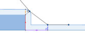
Then is utilized to cut the space that is with closer than . It is such a state that with straight line cut curve on . While not adequate to cut, it should be that is with a lower bound of as in Fig. 4f. Otherwise it will be with a lower bound of as in Fig. 4h if it is not as close as .
is a critic point that be able to touch the top end of curve with flipper horizontally. It is defined as the lower bound of for following states, such as Fig. 4j. Then with set the critical point to indicate whether can still touch the ground. In that is the farther region, sure, it can, and thus upper bound of won’t be restricted by obstacle. In , however, the upper bound is the case touch the vertical plane of stair while flipper perpendicular to the ground.
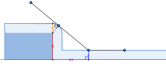
Keep moving forward, we will reach that its on the bottom of curve. It shows the first time robot body touches the stair edge. Between and is the region that won’t be able to be tangent to curve. Stop here the won’t lift from ground for the non-tangency of body to curve. While make a big difference that its following state are all for and the body will be always tangent to the curve.
, that both and of it are tangent to the curve, with lying on the upper plane of the step, sets a division for following state of into and .
For that is with lower than as in Fig. 4o, we constraint it should also have its front flipper touch curve for stable issue. While with higher than should have its touch the stair plane to avoid the sharp drop caused by gravity.
To note that, when is high, for example, it is possible that . And thus the will disappeared or say, be part of . But we are considering the duty of is to indicate whether can leave the ground. So the that is in should also follow the rules in .
Actually, we check the state with critical points from to in order, just to ensure the duty of critical point will carry out.


One possible space can be found in Fig. 5a.
II-B2 Path Search
In this part, we do not build the whole space of parameters and make a search, because the space is large and it takes a long time to build the graph and search, which is not viable for rescue robot autonomous run.
So alternatively we make a simple implementation. First, we discrete the from some triggered distance to with certain interval . Then from large to small, we find the possible state of next and find the closest triplet point to current point and update the current point. The path can be generated efficiently and will finally reach the target. It is more clear in Algorithm. 2. The function used here take as input, and it will create batches of pairs with a range of . Then we feed those batches of pairs into state check function as in Section II-B1. The distance function we used here is
with a weight to adjust the effect of on distance computing.
return
II-B3 Recover the Whole Parameter
From above parts, we achieved a path of triplet . However it is not adequate to reveal on the robot morphology. So here we further compute the back flipper angle and evaluate the robot and , which is the distance from to its cut-off point. does not count if the base does not touch the curve part of dilated ground.
Given a triplet of , we will use state check similar to Section II-B1 to find the group of morphology it belongs and then compute its and correspondingly. For the back flipper angle, if does not leave the ground, we would set to make the whole back flipper on the ground after . Otherwise, we should ensure the end-point of it touch the ground if back flipper is not tangent to the curve. While back flipper is tangent to the curve, the will also be set correspondingly.
II-C Path Following for Rescue Robot
Since we have obtained the global path with each point a triplet of (, , ) for a configuration, it is also important to make real robot move following the path.
For each triplet point, we send it into a similar state checking function shown in Section II-B1 to determine its current state and compute the corresponding extra parameters.
In this part, we will also use these three additional parameters , and .
For the path following, we use , and to determine the wanted angle changing and track moving.
and is easy to compute while requires more concern because we should also consider the touched point on the track.
While , is still on the ground, the will effect the movement as positive will make move back a little bit. So we compute
. When , from our design, base should be on the stair edges. So we use to compute as
.
III Experiment
III-A Setting
The robot we use is shown in Fig. 2. It is a small size tracked robot. Its wheels on the track and flipper are with the same radius. Which means we can draw a line between joints and thus its structure fit for our design of simplification as in Fig. 1. For this robot, the length of robot track, (from to ) is cm, the length of front flipper, (from to ) and of back flipper (from to ), are both cm. The radius of the robot wheel is cm.
To record the pose of the robot while moving to provide ground truth, a tracking system, OptiTrack, has been utilized to locate the position of joints. vrpn server is activated with Motive software under the same network as robot.
The implementation of our algorithm is with Python. We use ROS to coordinate with the robot. On the motor control, ROS dynamixel_workbench_control package has been utilized. To receive the true location from tracking system together with robot parameter, vrpn client runs under the same ROS master as the robot.
During the experiment, the lower bound is set and upper bound that are restricted by the installation of motors. On the flipper planning part, we discrete with an interval m, with interval and with interval rad if result for given pair is a range of value.
Because the upper bound of dominates the height it can climb, so we first choose a cm step that is considered to be high. Then cm and cm are also included in the experiment. Because the start position does not effect the result of planning, we unified the initial distance to m for all cases. Also, we set in distance function as .
This work is only analyzed on the straight to obstacle case. We are wondering if it is possible to climb on a step if it is not straight. For that we rotate the stair as the middle line to stair still m and run. The rotation angle is from to with interval.
The implementation can be found on github111willbereleasedifpapergetsaccepted..
III-B Evaluation
After the state check for a mesh of and , we can achieve the space of possible morphology represented by triplet . We discrete with for demonstration and default setting for and . Then the generated space is as Fig. 5a. It demonstrates how the configuration space looks like. We can observe that it consists of one plane and one curve surface that is from far to close. The joint between two surface is a point that can start leave the ground. And thus it is where the critical point with located.


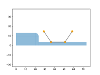

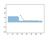


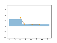


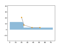


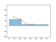

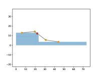

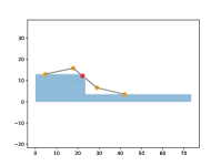


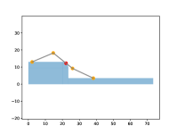


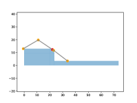
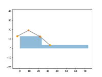
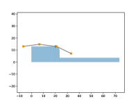
Then with interval , we make a path in Fig. 5b. To check the correctness of each point we plot the morphology of each path point in Fig. 6.
Then we evaluate the performance of real robot path following as in Fig. 7. The running of real robot is shown in the attached video.
To demonstrate the performance and safety of our algorithm, we make the robot run on three different height steps and record its , , and .


In the path following, when the wheel moves adequate long for target , it will trigger the next target , , and .
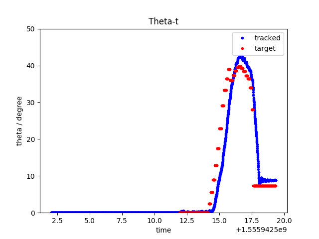
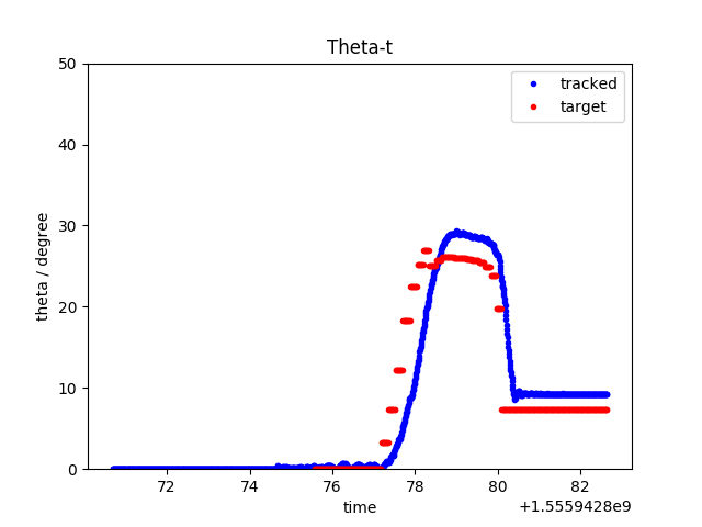
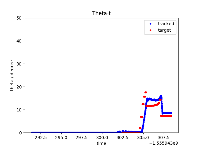
In Fig. 7, the three rows are for flipper angle, , robot elevation angle and elevation angle. The three column are for cm, cm and cm stairs, respectively.
In the first row the current , and its targets at time are shown. We can find the current flipper angle closely follows the target angle.
Then the second row shows the target and the tracked at each time. We find that the tracked always follows the target. However, the tracked does not reach the final target , which is this way because of our implementation: the robot is following the target that is pre-assumed to be a simplified condition and only the base track will matter on movement. In addition, it do not have close loop on . Thus error may happen with slip between track and ground.
The third row shows the changing elevation angle as robot moving forward. We find that in both case, the angle drop is not sharp, we consider it make sense because in our design, while robot is on the stair edge, front flipper is required to touch the floor to avoid the sharp leaning and thus more safety for robot. However, in Fig. 7i, the target and tracked seems mismatched. And it is also raised by the following and non-close loop issue. To note that, the final is not , since our final target as in Fig. 6 is close but not .
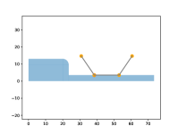
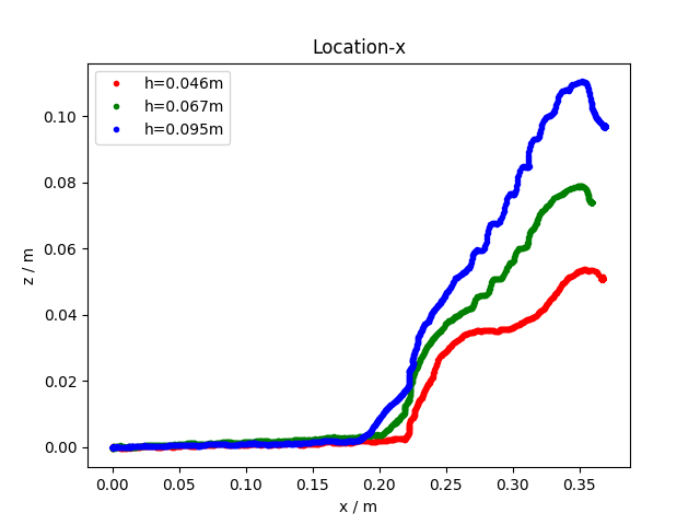
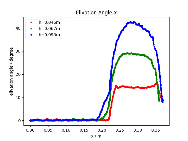
In Fig. 8, we shows the z-x and elevation angle-x plots for those three step cases. Here x and z is the movement and height for the center of robot (center of rectangle from the four joints , that are , for both left and right sides, on real robot). Fig. 8a demonstrates the trajectory of the center as it rises up and drop down, clearly revealed the movement of robot. Fig. 8b also shows the changing of elevation angle. We can find the higher step tends to require larger elevation angle and its changing is more smooth from the plot.
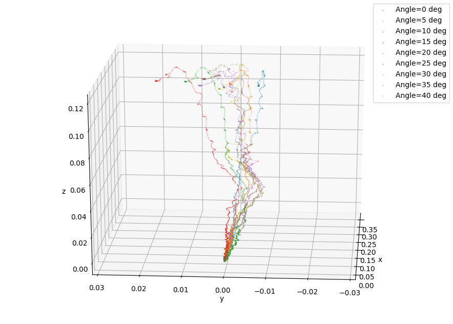

To further test the mobility when stair is not perfectly straight to robot, we rotate the step with angle from to and find it can also works well as shown in the video. The trajectories of the robot center are in Fig. 9. They all finished the task with center on the same level of height as step. Also, the larger rotation tend to rise center earlier and end up little bit farther to the target.
IV Conclusion
In this work, we simplify the rescue robot control and represent its morphology with parameters , and . We are thus able to construct the parameter space for climbing a step. This work is so far the first algorithm that can build the configuration space for rescue robots on step climbing with flippers and it allows for continuous changing of the robot morphology. From our experiment on the real robot, it can well climb on the step with the implemented path following on our obtained path.
V Future Work
This work is our first step to make global planning for the movement of tracked robot with flipper. Later on, closed loop should be considered in path following for better self-localization. Also, this work provides constraints for the morphology of rescue robot, so we will attempt to implement dynamic control on top of it. Additionally, more complicate and generalized scenes should be considered.
References
- [1] R. Sheh, S. Schwertfeger, and A. Visser, “16 years of robocup rescue,” KI-Künstliche Intelligenz, vol. 30, no. 3-4, pp. 267–277, 2016.
- [2] A. I. Mourikis, N. Trawny, S. I. Roumeliotis, D. M. Helmick, and L. Matthies, “Autonomous stair climbing for tracked vehicles,” The International Journal of Robotics Research, vol. 26, no. 7, pp. 737–758, 2007.
- [3] S. Steplight, G. Egnal, S.-H. Jung, D. B. Walker, C. J. Taylor, and J. P. Ostrowski, “A mode-based sensor fusion approach to robotic stair-climbing,” in Proceedings. 2000 IEEE/RSJ International Conference on Intelligent Robots and Systems (IROS 2000)(Cat. No. 00CH37113), vol. 2. IEEE, 2000, pp. 1113–1118.
- [4] E. Mihankhah, A. Kalantari, E. Aboosaeedan, H. D. Taghirad, S. Ali, and A. Moosavian, “Autonomous staircase detection and stair climbing for a tracked mobile robot using fuzzy controller,” in 2008 IEEE International Conference on Robotics and Biomimetics. IEEE, 2009, pp. 1980–1985.
- [5] D. Endo, A. Watanabe, and K. Nagatani, “Stair climbing control for 4-dof tracked vehicle based on internal sensors,” Journal of Robotics, vol. 2017, 2017.
- [6] M. Pecka, K. Zimmermann, M. Reinstein, and T. Svoboda, “Controlling robot morphology from incomplete measurements,” IEEE Transactions on Industrial Electronics, vol. 64, no. 2, pp. 1773–1782, 2017.
- [7] T. Wiley, C. Sammut, B. Hengst, and I. Bratko, “A planning and learning hierarchy using qualitative reasoning for the on-line acquisition of robotic behaviors,” Adv. Cogn. Syst, vol. 4, pp. 93–112, 2016.
- [8] J. Liu, Y. Wang, S. Ma, and B. Li, “Analysis of stairs-climbing ability for a tracked reconfigurable modular robot,” in IEEE International Safety, Security and Rescue Rototics, Workshop, 2005. IEEE, 2005, pp. 36–41.
- [9] N. Li, S. Ma, B. Li, M. Wang, and Y. Wang, “An online stair-climbing control method for a transformable tracked robot,” in 2012 IEEE International Conference on Robotics and Automation. IEEE, 2012, pp. 923–929.
- [10] Q.-H. Vu, B.-S. Kim, and J.-B. Song, “Autonomous stair climbing algorithm for a small four-tracked robot,” in 2008 International Conference on Control, Automation and Systems. IEEE, 2008, pp. 2356–2360.
- [11] J. D. Martens and W. S. Newman, “Stabilization of a mobile robot climbing stairs,” in Proceedings of the 1994 IEEE International Conference on Robotics and Automation. IEEE, 1994, pp. 2501–2507.
- [12] Y. Xiong and L. Matthies, “Vision-guided autonomous stair climbing,” in Proceedings 2000 ICRA. Millennium Conference. IEEE International Conference on Robotics and Automation. Symposia Proceedings (Cat. No. 00CH37065), vol. 2. IEEE, 2000, pp. 1842–1847.
- [13] F. Colas, S. Mahesh, F. Pomerleau, M. Liu, and R. Siegwart, “3d path planning and execution for search and rescue ground robots,” in 2013 IEEE/RSJ International Conference on Intelligent Robots and Systems. IEEE, 2013, pp. 722–727.
- [14] K. Zimmermann, P. Zuzánek, M. Reinstein, T. Petříček, and V. Hlaváč, “Adaptive traversability of partially occluded obstacles,” in 2015 IEEE International Conference on Robotics and Automation (ICRA). IEEE, 2015, pp. 3959–3964.
- [15] M. Pecka, V. Šalanskỳ, K. Zimmermann, and T. Svoboda, “Autonomous flipper control with safety constraints,” in 2016 IEEE/RSJ International Conference on Intelligent Robots and Systems (IROS). IEEE, 2016, pp. 2889–2894.
- [16] M. Sokolov, I. Afanasyev, A. Klimchik, and N. Mavridis, “Hyperneat-based flipper control for a crawler robot motion in 3d simulation environment,” in 2017 IEEE International Conference on Robotics and Biomimetics (ROBIO). IEEE, 2017, pp. 2652–2656.
- [17] T. Wiley, I. Bratko, and C. Sammut, “A machine learning system for controlling a rescue robot,” in Robot World Cup. Springer, 2017, pp. 108–119.