Collaborative Localization and Tracking with Minimal Infrastructure
Abstract
Localization and tracking are two very active areas of research for robotics, automation, and the Internet-of-Things. Accurate tracking for a large number of devices usually requires deployment of substantial infrastructure (infrared tracking systems, cameras, wireless antennas, etc.), which is not ideal for inaccessible or protected environments. This paper stems from the challenge posed such environments: cover a large number of units spread over a large number of small rooms, with minimal required localization infrastructure. The idea is to accurately track the position of handheld devices or mobile robots, without interfering with its architecture. Using Ultra-Wide Band (UWB) devices, we leveraged our expertise in distributed and collaborative robotic systems to develop an novel solution requiring a minimal number of fixed anchors. We discuss a strategy to share the UWB network together with an Extended Kalman filter derivation to collaboratively locate and track UWB-equipped devices, and show results from our experimental campaign tracking visitors in the Chambord castle in France.
I INTRODUCTION
Indoor localization and tracking have the potential to unlock a plethora of new concepts and applications, both for autonomous system research and for public space enhancement. While many paths were explored already, it is challenging to deploy an absolute positioning system comparable to outdoor satellite-based GPS. Expensive and specialized setups can track devices or people within a limited zone using laser scans or camera arrays, but these solutions hardly fit a large building-wide tracking system. For applications in public spaces, i.e., commercial halls, museums, sports centers or schools, a localization system must be flexible, affordable and discreet. When deployed on handheld devices, such a system can then provide the users with a more interactive relation to the installations. On the other side of the spectrum, technology such as RFID, can cover a large area, but only with limited accuracy. Commercial products try to fill the gap (GiPStech, AccuWare, Locbee, etc.) with solutions coupling inertial measurements, geomagnetic data and available WiFi/Bluetooth beacons or routers. These are expected to reach at best one-meter accuracy, and quickly drift if not enough routers are visible.
Yet the market demands for such products grows. For instance, in museums, a localization-enabled audio-guide can help to guide the user while they navigate from room to room. It can provide accurate contextual self-guided tours including interactive quiz or treasure hunts, and be leveraged to share the users experience on social networks. From the museum operation perspective, it can provide an analytic of the floor traffic and even help with emergency protocols.
The solution presented in this paper uses Ultra-Wide Band (UWB) network-based measurements, able to exchange data even without line-of-sigh. In order to make our solution relevant for most commercial human tracking applications, we aim at 10cm accuracy and try to minimize the number of required fixed beacons (anchors). The general concept is that each device tracked has full or partial knowledge of its own position and this can be used to help others localize without anchors. To ensure an optimal use of the network for distance measurements, a central monitoring system can handle the dynamics of all moving devices, but it would require full connectivity over all the building rooms and thus numerous network extenders. However, we leverage principles from swarm robotics based only on neighbors interactions to achieve consensus on the UWB network usage. Indeed, sharing a UWB network in a decentralized fashion requires synchronization and time-sharing between the devices, so as to avoid message collisions. To address the challenge of time-division multiple access we implement a decentralized slot assignment protocol.
The next section, Sec. II, introduces the research work that inspired us in the design of our solution. Sec. III details our strategy to synchronize the devices and share the network use among them. Then Sec. IV summarizes the measurement types and presents our implementation of an Extended Kalman Filter. We put everything together and discuss the performance of the system in Sec. V by presenting experiments conducted at the Chambord castle and in our laboratory. Finally, Sec. VI describes how the solution will be enhanced before its final large-scale deployment in the castle scheduled in Fall 2019.
II RELATED WORK
Our goal is to provide a easily installing global position system for visitors or robots with UWB technology. There are lots of research results using UWB sensors for localization. However, most are used to tracking one object with fixed anchors setup [1, 2, 3, 4]. A system proposed in [17] works with multiple robots cooperative localization. However the use of UWB still belongs to fixed anchors usage and they have separate customized sensor for relative position estimation. One of the most related papers[5] tracking three robots is also a centralized system considering the UWB network, which almost neglects the difficulties of managing usage of UWB network. To the best of our knowledge, this paper is the first practical system using UWB technology to do localization for a group or multiple objects collaboratively in decentralized manner.
II-A Management of UWB network
In order to share our UWB network without the need for a master supervision, we used two strategies: synchronization and Time-Division Multiple Access (TDMA). The former was used in several works focused on sensor network applications for multiple concurrent measurements. A popular approach, the flooding-time synchronization protocol (FTSP)[6], reaches an average time offset between arbitrary nodes of the system. However, when considering large scattered configurations, the nodes that require tight synchronization are usually the closest ones. This was addressed using gradient-based synchronization [7, 8], which gives more importance to the closest nodes to minimize the offset between clocks. To the best of our knowledge, these techniques were never applied to the distributed usage of a UWB network.
The second body of knowledge (i.e., TDMA) includes many mechanisms to reach a consensus on how to share network access between multiple devices in a distributed way. Paper [9] gives an overview of TDMA slot assignment algorithms. The influential algorithm Distributed Multichannel TDMA Slot Assignment Protocol (USAP) [10] allows nodes to get conflict-free slot assignment in a decentralized way using local topology information in dynamic configurations. This original strategy was shown to underuse the available slots, and even the extended versions (MA) [11] still had to cope with a constraint between the number of available channels and the maximum number of neighbors considered. Furthermore, Dastango [12] showed that the convergence of USAP MA is sensitive to the number of slots per frame, requiring careful tuning from the integrator. A handful of further USAP extensions [13, 14] provide a more flexible and more optimal usage of channels with adaptive frame lengths. However, the structure of their control packets became more complex, which results in heavier communication load. Chaudhary and Scheers [15] proposed a priority mechanism allowing nodes with one-hop neighbors to be assigned slots first. While it achieved a more optimal channel usage, they did not consider the dynamic network topology. In summary, the design challenge is to get optimal channel usage while keeping low communication load. Only two values are used in our control packets, which is even simpler than the Net Manager Operational Packet(NMOP) used in the original USAP [10].
II-B Localization by sensor fusion
Works in mobile robotics have shown reliable performance of the UWB/IMU combination for indoor positioning of rovers [1] and quadcopters [16]. However, both focused on a single robot tracking and used a centralized UWB setup, synchronized over Ethernet.
Benini et al. [1] considered the IMU as the process input and they derived a non-linear process noise including bias. Merging the Ubisense (UWB) measurement with a low-cost IMU, they showed that the localization accuracy can be improved. Mueller et al. [16] used the IMU to estimate the drag force of quadcopters and input this measure into their EKF, together with measurements from a custom UWB radio. These examples demonstrate the high accuracy ( cm) of their strategy. For a collaborative strategy on multi-agent localization, the work of Prorok and Martinoli [17] reached comparable accuracy ( cm) modeling the UWB measurement error and compensating it with relative positioning between the robots (a separated module based on infrared). Instead of an EKF, they used a particle filter, also rather commonly used with UWB. A recent study on the collaborative use of UWB showed that two-way-ranging can give better results than simple time-difference of arrival [18]. Their results confirmed our design choices, as previous setup conducted with a fixed transmission scheme (not dynamic) and the tags position computed on a central computer. Finally, the design of our EKF was inspired by previous works that focused on tracking a single UWB tag [19, 20].
III SHARING THE NETWORK
While current UWB solutions can achieve the accuracy required for interactive museum devices, all the current commercial products are centralized. They require either a tight synchronization between the anchors (direct time-of-flight measurements), done on a separated common network, or the allocation of network slots through a master node. In both cases, the deployment requires full connectivity of the tags and anchors at all time. However, to limit the number of anchors and other network-related devices (router, repeater, etc.), each tag should be able to adapt its network usage collaborating with its current neighbors. We achieved this by first synchronizing all nearby tags and then splitting a cycle in slots attributed automatically to each tag, in our case audio-guides or other user devices to be tracked. The whole transmission mechanism runs in cycles, as shown in Fig. 1: first the synchronization, then the slots attribution, and finally each slot execution. Each phase of the cycle uses specific custom serialized messages transmitted over the UWB network.

III-A Synchronization
Our scenario has two characteristics influencing the selection of a synchronization algorithm: 1. a highly dynamic environment and 2. its local network usage. The system is meant to be deployed in a museum each day, meaning that a single user may be visiting alone, or hundreds simultaneously, moving from room to room, thus quickly changing the network topology. A group of people in the same room will be fully connected, while the topology will include multiple hops and eventually be disconnected when moving away. It would be rather difficult to keep all visitors synchronized. In any case, localization uses neighboring anchors and tags, so nodes that are far away can be considered less important for synchronization. A gradient-based synchronization solution is well suited to this context.
From [7], each tag uses its hardware clock:
| (1) |
where is the clock rate at time and its offset at time . This hardware clock should not be directly adjusted, so we define a logical clock instead:
| (2) |
where is the relative rate compensating for the drift of the logical clock relative to the hardware clock and , the logical clock offset. The compensation rate can be set to 1, if we postulate that our hardware clocks are sufficiently accurate (relative to our scenario). This way, we consider only a single offset to maintain a synchronized logical clock. The objective is for each tag to maintain this logical clock as close as possible to its neighbors’. The messages sent in this phase of the transmission cycle, syn msg, contains a single piece of information: the logical clock value when the message was sent. Each tag receives these messages from all neighbors , so it can adjust its own clock by computing the average offset:
| (3) |
where is the clock difference between tag and its neighbor with an estimated communication delay . The delays in message transmission can be sending delay, network access delay, propagation delay, and receiving delay. The accurate estimation of these delays requires tedious low-level control of the radios, but it is not mandatory to estimate the overall . Empirically, the average communication delay can be estimated using simple broadcasting and receiving scripts.
In the synchronization phase, the network usage is not controlled, all tags may access it simultaneously. To minimize collisions the tags broadcast their syn msg randomly with a greater probability of listening to the channel than broadcasting to it. It is important to note that some UWB systems will hang if they experience too many packet collisions, but this strategy generates collisions over custom messages, not using the network for measurements. The worst case is a lost message, which can be coped with using a sufficiently long synchronization time. All the tags adjust their clocks towards the average of their neighbors. When the difference between the clock and the neighbors’ average is smaller than a set threshold, or the synchronization timed out, the tags are considered synchronized and keep their logical clock until the next cycle.
III-B TDMA
Once all tags are operating in sync, a time-based schedule can be generated so all tags can access the UWB network in sequence for their measurements. A TDMA algorithm includes two processes: scheduling and execution. In the scheduling process, all neighboring tags negotiate which slots of the execution phase they can have, converging to a consensus on the final sequence. To reach consensus, they exchange tdma msg, serialized packets including three pieces of information: the sender id (usually provided by the UWB device controller), an action code, and a requested slot id.
If the execution phase need to be theoretically free of collision following the agreed sequence, the scheduling phase has to be scripted to ensure its performance. Following the synchronization phase, we create a neighbor table in each tag. This table evolves with new messages coming in and by means of a garbage collector. This list is used to set an initial sequence using ascending IDs. This strategy assumes that a tag leaving the group creates an empty slot in the schedule (not requesting any slots for the execution) and a new tag entering the group waits for the next round of scheduling.
Every tag maintains two TDMA-related tables for scheduling: a sent list and a received list. From these tables, the tage can derive a list of free slots IDs. When broadcasting, the tag selects one of these free slots. While in the listening state, the tags update their lists with the new messages coming in.
Inspired by USAP, our implementation solves the TDMA schedule problem using only broadcast messages. No peer-to-peer communication is needed, which increases the convergence time. We introduce and example to clarify the algorithm detailed in Alg. 1 and show how we avoid scheduling conflicts. The five small circles illustrated in Fig. 2 are five tags, or robots. To avoid a loaded figure, we only draw the communication ranges of tags and , which is enough to describe all cases. Tags , , and are within the communication range of tags . Also, tags , , are within the range of tag . The illustration is a snapshot of the scheduling process.
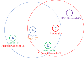
When broadcasting messages, a tag may use one of three actions: slot proposal, proposal rejection, and proposal cancellation. The text under the circles represents the tag’s chosen actions with the letter in parenthesis representing the source of the incoming message. The first tag to broadcast starts with a slot proposal and all listeners update their received list (as tags and when receiving from ), as in lines 10-11 of Alg. 1, unless this slot is already flagged as attributed in their list. In this case, the tag discovering a conflict sends a proposal rejection at its next broadcasting slot. The tag that first sent a slot proposal may never have received a proposal from a node with whom no direct link exists. Such a conflict with a hidden node is resolved with our broadcasting strategy. In Fig. 2, tag sees the conflict. A proposal rejection message uses the conflicting tag ID as the action code. When a tag gets this type of message, it checks if it is the source of the conflict and if it is the case, emits a proposal cancellation message, as in lines 15-18 of Alg. 1. Otherwise, if the conflicting ID fits the one attributed in the received list, then it knows the tag with this conflicting ID causes a conflict and the received list entry is erased, as in lines 19-20 of Alg. 1. As showed in Fig. 2, both tags and canceled the proposal of tag , but following different message flows. Tag got the proposal rejection directly from tag , but is not a neighbor of , so it got only the cancellation when broadcast by . This logic prevents conflicts to emerge in the schedule, even with hidden nodes.
It should be noted that for a tag that is not a neighbor of tag , like , the proposal rejection message is ignored since never had a relative entry in the received list in the first place.
IV TRACKING THE VISITORS
Our interest lies in the estimation of the real-time Cartesian position of the devices in an absolute reference frame of the building. Which means that, for now, we are not looking at the orientation part of the pose estimation problem. Three different inputs are considered in the state estimation filter: range from a neighbor, range from an anchor, and trilateration using many anchor. At each TDMA slot, the state estimation update follows the decision flow of Fig. 3.
IV-A Ranging
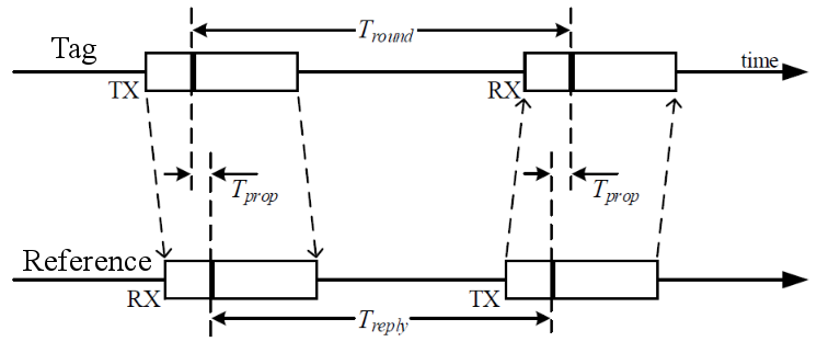
The two most common mechanisms for UWB-based localization are Two-Way-Ranging (Pozyx, SewIO) and Time-Difference-Of-Arrival (TDoA) (BitCraze, Ubisense). While the latter requires accurate synchronization of all the devices, it computes the distance using a single synchronized ping from all anchors. TWR, however, uses at least two messages, as shown in Fig. 4 for the single-sided version, and is consequently slower. The accuracy of a TWR measurement is independent of each device’s clock, thus more robust to a dynamic and large group of tags. For instance, the TDoA mechanism of Loco (BitCraze) supports a maximum number of 8 anchors, all in sight. To support more devices, Pozyx [21] developed a strategy exchanging the synchronization packets for all anchors over a separated Ethernet or Wi-Fi network. This approach would require too many communication relays in a building with walls that are impermeable to electromagnetic waves.
The measurement becomes the average of the time difference between messages:
| (4) |
From this measurement, the tag position can be derived, since the distance is:
| (5) | ||||
| (6) |
with , the speed of light, , the coordinate of the tag position and , of the reference node (anchor or neighbor).
IV-B Trilateration
The Pozyx system provides a filtered output of the Cartesian coordinates of a tag. Their algorithm can work in 2D with three anchors or in 3D with four anchors. The anchors can be either manually entered in the code as a dictionary including their absolute position or discovered and automatically calibrated using ranging measurements. The second option is known to be less accurate and so all our tests were made with manual measurements of the anchors. The accuracy of the measurement changes over the region covered by the anchors. We estimated an average variance of the measurement, while keeping a tag standing still for five minutes in three different positions in the work space and computing its position at approximately 30Hz using four anchors: . The anchors’ position were obtained from a camera-based motion capture (Optitrack).
IV-C Extended Kalman Filter
We implemented an Kalman filter to compute the three degrees of freedom in translation and their rate of change, based on a changing observation vector . Since we expect a smooth continuous movement, the state transition matrix is a discrete time model of first order:
| (7) |
and is a 22 zero matrix, where is the time elapsed since the last update of the filter. It allows us to compute the Kalman prediction:
| (8) |
The prediction is then updated from the residuals vector, :
| (9) |
where is the Kalman gain matrix resulting from
| (10) |
and
| (11) |
with and , respectively the observation noise and the observation matrix, varying with the available measurements. The process noise, is implemented to decrease the filter confidence on its model proportionally to the elapsed time since the last update:
| (12) |
At that point the only remaining terms to defined are the observation matrix and the observation noise , following if the measurements are from trilateration or range only. For trilateration, , , the three coordinates output by the doPositioning algorithm, and
| (13) |
The residuals vector is then .
However, for ranging, the measurement is not linearly related to the states (Equ. 6), thus
| (14) |
and the residual is computed from the predicted state to estimate the distance measured, . We compute the measurement noise matrix with a confidence value for the range input. Since the anchors are manually calibrated and their position hardcoded in each tag, the confidence just depends on the time passed since the measurement. However, ranging with other visitors involves using their estimated positions, which has an unknown level of precision. As an indicator of the measurement accuracy, we use the condition number of the covariance matrix . The ranging is noise is:
| (15) |
where . Finally, since ranging measurements can be subject to wave propagation artifacts, we check the estimated distance from the predicted state of the EKF and bound the accepted readings to a maximum. If no measurements are available, for instance while waiting for the UWB network to be available, we update the EKF without measurements, but it is expected to drift slowly.
V EXPERIMENTS
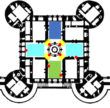
The challenge that initiated this work is to track visitors in a museum with only minimal infrastructure. To test the limit of our solution, we created different zones, as shown in Fig. 5: varying the number of anchors (4, 3, 2 or 0). Seven tags, or visitors, were moving around, following pre-defined goals in each zone, marked on the floor. We tested the synchronization plus time management strategy to ensure no collision on the UWB network during localization, and the accuracy of the tracking.
We started all tags together in the green zone. They first synchronized, then coordinated. They reached a maximum time offset, with regards to their neighbors average, of . In all cases, as shown in Fig. 1, synchronization occurs again at the beginning of the next cycle, most likely with a different configuration of neighbors. The schedule phase had slots pre-attributed following ascending IDs and until reaching consensus on the scheduling, after which the tags wait for their slots.

Fig. 6 shows the resulting scheduling tables of one run with the seven tags. The number of slots available for scheduling is 25, selected empirically to ensure all seven tags get at least a slot, demonstrated in the first schedule table Start A of Fig. 6. It should be noted that more slots do not influence the frequency of the localization phase, since each tag will be attributed multiple slots until the schedule is filled. This is also visible at all checkpoints (Bx, Cx) of Fig. 6, in which the tags get more slots then the initial scheduling. An interesting behavior can be observed between the schedule of Point B0 and Point B1: one member of the B1 group received messages from Tag105 and blocked most slots selected by this tag in group B1. This observation relates to the hidden node concept discussed in Sec. III.
Although empty slots are visible in each schedule, the main contribution is to ensure all possible conflicts are avoided on the UWB network.
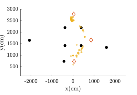
After all tags get an approved schedule table, they start positioning themselves, following the decision tree shown in Fig.3. The result of a visitor’s run is shown in Fig. 7, walking from the lower red diamond to the right one and finally to the top one. Due to the few resources (people and time) available during our experiments in the castle, the tracking results were not as accurate as expected from our simulations. The limitations are mainly attributed to the lack of precision on the anchors position, as well as the precision of the ground truth (goals marked on the ground).
With a proper ground truth, the effect of each measurement type can be highlighted, as shown in Fig. 8. Each sequence without measurements (red dots) push the EKF state to slowly drift. The trilateration measurements (green dots) are clearly the most accurate, and our range inputs stay under an acceptable average error of 9 cm.
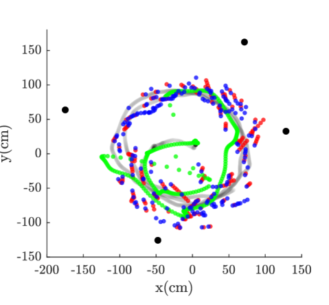
We confirmed the two contributions of this localization strategy: none of the tags experienced collision while conducting range measurements or trilateration, and our estimator stays under an average error of 10 cm.
VI FUTURE WORK
Our strategy showed good performance in terms of synchronization and time management, so it definitely allows for multiple tags to dynamically share a common UWB network. As for the tracking system, some information, specific to this context can be added to the workflow to help increase the accuracy. Most visitors are walking and so using the IMU, a pedometer approximation [22, 23] could give a more accurate measurement than using the raw acceleration. Also, since the map of the building is often available, each tag can know in which zone it is as soon as it sees an anchor or from dead reckoning estimation. This information can help limit the drift and remove outliers from the measurements.
These extensions will be evaluated before the final deployment, scheduled in fall 2019.
ACKNOWLEDGMENT
This project is an original idea of the NXI Gestatio [ReevesSt-Onge], a design laboratory of the University of Quebec in Montreal. The authors would like to acknowledge the support of the Chambord Castle team for the experiments.
References
- [1] A. Benini, A. Mancini, A. Marinelli, and S. Longhi, “A Biased Extended Kalman Filter for Indoor Localization of a Mobile Agent using Low-Cost IMU and UWB Wireless Sensor Network,” in IFAC Proceedings Volumes, vol. 45, no. 22, 2012, pp. 735–740.
- [2] J. Tiemann, F. Eckermann, and C. Wietfeld, “ATLAS - an open-source TDOA-based ultra-wideband localization system.” IEEE, pp. 1–6. [Online]. Available: http://ieeexplore.ieee.org/document/7743707/
- [3] V. Mai, M. Kamel, M. Krebs, A. Schaffner, D. Meier, L. Paull, and R. Siegwart, “Local positioning system using UWB range measurements for an unmanned blimp,” vol. 3, no. 4, pp. 2971–2978.
- [4] A. Wallar, B. Araki, R. Chang, J. Alonso-Mora, and D. Rus, “Foresight: Remote sensing for autonomous vehicles using a small unmanned aerial vehicle,” in Field and Service Robotics. Springer, pp. 591–604.
- [5] K. Guo, Z. Qiu, W. Meng, L. Xie, and R. Teo, “Ultra-wideband based cooperative relative localization algorithm and experiments for multiple unmanned aerial vehicles in GPS denied environments,” vol. 9, no. 3, pp. 169–186. [Online]. Available: https://doi.org/10.1177/1756829317695564
- [6] M. Maróti, B. Kusy, G. Simon, and A. Lédeczi, “The flooding time synchronization protocol.” ACM Press, 2004, p. 39. [Online]. Available: http://portal.acm.org/citation.cfm?doid=1031495.1031501
- [7] R. Fan and N. Lynch, “Gradient clock synchronization,” Distributed Computing, vol. 18, no. 4, pp. 255–266, 2006.
- [8] P. Sommer and R. Wattenhofer, “Gradient Clock Synchronization in Wireless Sensor Networks,” in Proceedings of the 2009 International Conference on Information Processing in Sensor Networks, ser. IPSN ’09. Washington, DC, USA: IEEE Computer Society, 2009, pp. 37–48.
- [9] C. Xuelin and S. Zuxun, “An overview of slot assignment (SA) for TDMA,” in 2015 IEEE International Conference on Signal Processing, Communications and Computing (ICSPCC), Sep. 2015, pp. 1–5.
- [10] C. D. Young, “USAP: a unifying dynamic distributed multichannel TDMA slot assignment protocol,” in MILCOM ’96, Conference Proceedings, IEEE Military Communications Conference, 1996, vol. 1, Oct. 1996, pp. 235–239 vol.1.
- [11] ——, “USAP multiple broadcast access: transmitter- and receiver-directed dynamic resource allocation for mobile, multihop, multichannel, wireless networking,” in MILCOM 2000 Proceedings. 21st Century Military Communications. Architectures and Technologies for Information Superiority (Cat. No.00CH37155), vol. 1, 2000, pp. 549–553 vol.1.
- [12] S. Dastangoo, T. G. Macdonald, D. Reinharth, and C. Burns, “Performance analysis of distributed time division multiple access protocols in mobile ad hoc environments,” in MILCOM 2009 - 2009 IEEE Military Communications Conference, Oct. 2009, pp. 1–7.
- [13] A. Kanzaki, T. Uemukai, T. Hara, and S. Nishio, “Dynamic TDMA slot assignment in ad hoc networks,” in 17th International Conference on Advanced Information Networking and Applications, 2003. AINA 2003., pp. 330–335.
- [14] W. Li, J. Wei, and S. Wang, “An evolutionary-dynamic TDMA slot assignment protocol for ad hoc networks,” in 2007 IEEE Wireless Communications and Networking Conference, pp. 138–142.
- [15] M. H. Chaudhary and B. Scheers, “High spatial-reuse distributed slot assignment protocol for wireless ad hoc networks,” in 2012 Military Communications and Information Systems Conference (MCC), pp. 1–8.
- [16] M. W. Mueller, M. Hamer, and R. D’Andrea, “Fusing ultra-wideband range measurements with accelerometers and rate gyroscopes for quadrocopter state estimation,” Proceedings - IEEE International Conference on Robotics and Automation, vol. 2015-June, no. June, pp. 1730–1736, 2015.
- [17] A. Prorok and A. Martinoli, “Accurate indoor localization with ultra-wideband using spatial models and collaboration,” International Journal of Robotics Research, vol. 33, no. 4, pp. 547–568, 2014.
- [18] M. Kolakowski and V. Djaja-Josko, “TDOA-TWR based positioning algorithm for UWB localization system,” 2016 21st International Conference on Microwave, Radar and Wireless Communications, MIKON 2016, 2016.
- [19] J. D. Hol, F. Dijkstra, H. Luinge, and T. B. Schön, “Tightly Coupled UWB / IMU Pose Estimation,” IEEE International Conference on Ultra-Wideband, vol. 2009, pp. 688–692, 2009.
- [20] S. Sczyslo, J. Schroeder, S. Galler, and T. Kaiser, “Hybrid localization using UWB and inertial sensors,” Proceeedings of The 2008 IEEE International Conference on Ultra-Wideband, ICUWB 2008, vol. 3, pp. 89–92, 2008.
- [21] “Pozyx - centimeter positioning for Arduino.” [Online]. Available: https://www.pozyx.io
- [22] E. D. Marinis and O. Gasparini, “Location and tracking of pedestrians based on inertial navigation,” in Proceedings of the 1st International Conference on Wireless Technologies for Humanitarian Relief, 2011.
- [23] S. Jayalath and N. Abhayasinghe, “A gyroscopic data based pedometer algorithm,” Proceedings of the 8th International Conference on Computer Science and Education, ICCSE 2013, no. Iccse, pp. 551–555, 2013.