∎
22email: ines.hajri.svv@gmail.com, ar.goknil@gmail.com, fabrizio.pastore@uni.lu, lionel.briand@uni.lu 33institutetext: L. C. Briand 44institutetext: University of Ottawa
Automating System Test Case Classification and Prioritization for Use Case-Driven Testing in Product Lines
Abstract
Product Line Engineering (PLE) is a crucial practice in many software development environments where software systems are complex and developed for multiple customers with varying needs. At the same time, many development processes are use case-driven and this strongly influences their requirements engineering and system testing practices. In this paper, we propose, apply, and assess an automated system test case classification and prioritization approach specifically targeting system testing in the context of use case-driven development of product families. Our approach provides: (i) automated support to classify, for a new product in a product family, relevant and valid system test cases associated with previous products, and (ii) automated prioritization of system test cases using multiple risk factors such as fault-proneness of requirements and requirements volatility in a product family. Our evaluation was performed in the context of an industrial product family in the automotive domain. Results provide empirical evidence that we propose a practical and beneficial way to classify and prioritize system test cases for industrial product lines.
Keywords:
Product Line Engineering Use Case Driven Development Regression Testing Test Case Selection and Prioritization Automotive Requirements Engineering1 Introduction
Product Line Engineering (PLE) is a common practice in many domains such as automotive and avionics to enhance product quality, to reduce development costs, and to improve time-to-market Pohl05 . In such domains, many development processes are use case-driven and this strongly influences their requirements engineering and system testing practices Nebut2006 ; Nebut06 ; Wang2015a ; Wang2015b . For example, IEE S.A. (in the following “IEE”) IEE , a leading supplier of embedded software and hardware systems in the automotive domain and the case study supplier in this paper, develops automotive sensing systems enhancing safety and comfort in vehicles for multiple major car manufacturers worldwide. The current development and testing practice at IEE is use case-driven, and IEE, like many other development environments, follows the common product line testing strategy referred to as opportunistic reuse of test assets Neto2011 . A new product line is typically started with a first product from an initial customer. Analysts elicit requirements as use case specifications and then derive system test cases from these specifications. For each subsequent customer for that product, the analysts start from the current use case specifications, and negotiate variabilities with the customer to produce new specifications. They then manually choose and prioritize, from the existing test suite of the previous product(s), test cases that can and need to be rerun to ensure existing, unmodified functionalities are still working correctly in the new product. With this form of test reuse, there is no structured, automated method that supports the activity of classifying and prioritizing test cases. It is fully manual, error-prone and time-consuming, which leads to ad-hoc change management for use case models (use case diagrams and specifications) and system test cases in product lines. Therefore, product line test case classification and prioritization techniques, based on a dedicated use case modeling methodology, are needed to automate the reuse of system test cases in the context of use case-driven development.
The need for supporting PLE for the purpose of test automation has already been acknowledged and many product line testing approaches have been proposed in the literature Neto2011 ; do2014strategies ; Engstrom2011 ; Lee-SPLTestingSurvey-SPLC-2012 ; Runeson2012 . Most of the existing approaches follow the product line testing strategy design test assets for reuse Neto2011 in which test assets, e.g., abstract test cases or behavioral models, are created in advance for the entire product family, including common and reusable parts. When a new product is developed, test assets are selected to be reused, extended, and refined into product-specific test cases. Due to deadline pressures and limited resources, many companies, including IEE, find the upfront creation of test assets to be impractical because of the large amount of manual effort required before there are (enough) customers to justify it.
Lity et al. Lity2016 ; Lochau2014 ; Lity2012 propose a test case selection approach which follows an alternative product line testing strategy, i.e., incremental testing of product lines Neto2011 . In this strategy, the initial product is tested individually and the following products are tested using regression testing techniques, i.e., test case selection and prioritization. The approach does not require the entire test suite of the product family to be generated in advance since the test cases of the new product are selected and derived incrementally from the test suites of the previous product(s). Its main limitation is the need for detailed behavioral models, e.g., finite state machines and sequence diagrams, which rarely exist in industrial practice since software development and testing are typically driven by requirements in Natural Language (NL) and behavioral models are typically specified only for a limited set of critical system features Larman-Applying-2002 . To evaluate the applicability of behavioral modeling in practice, we asked IEE engineers to specify System Sequence Diagrams (SSDs) for some of the use cases in one of their projects, at a level of detail that was appropriate for our objectives. For example, the SSD for one of the mid-size use cases included 74 messages, 19 nested blocks, and 24 references to other SSDs that had to be derived. This was considered too complex for the engineers and required significant help from the authors of this paper, and many iterations and meetings. The main problem with sequence diagrams is the nested blocks (loops that cover alternative flows backwarding) for loops and references to other sequence diagrams. With these structures, it was not feasible to follow the execution flow visually for the engineers. Our conclusion is that the adoption of behavioral modeling, at the level of detail required for automated test case selection, is typically not practical for system test automation unless detailed behavioral models are already used for other purposes, e.g., software design.
Many approaches for test case classification and prioritization require the source code of the system under test together with code coverage information Yoo2012 . However, this information is often partially available in industrial contexts. Indeed, when system testing is outsourced to companies or independent test teams, the source code of the system under test is often partially or not available. For example, test teams may have access only to the source code of a single product, not the entire product line. In addition, structural coverage information is often unavailable in the case of embedded systems. Indeed, traditional compiler-based methods used to collect coverage data Yang2006ASO cannot be applied when test cases need to be run on dedicated hardware. These are the main motivations in this paper to rely on a requirements-driven approach to test case classification and prioritization.
In our previous work Hajri2015 , we proposed the Product line Use case modeling Method (PUM), which supports variability modeling in Product Line (PL) use case diagrams and specifications in NL, intentionally avoiding any reliance on feature models or behavioral models such as activity and sequence diagrams. PUM relies on the Restricted Use Case Modeling method (RUCM) Yue2013 , which introduces a template with keywords and restriction rules to reduce ambiguity and to enable automated analysis of use case specifications. RUCM has been successfully applied in many domains (e.g., Zhang2018 ; Wang2015a ; Hajri2015 ; Mai2018 ; Mai2018b ; Hajri2017b ; Mai2019 ; wang2019automatic ). Based on PUM, we developed a use case-driven configuration approach Hajri2016c ; Hajri2016b guiding engineers in making configuration decisions and automatically generating Product Specific (PS) use case models. It is supported by a tool, PUMConf (Product line Use case Model Configurator), integrated with IBM DOORS.
In this paper, we propose, apply and assess an approach for the definition, selection, and prioritization of test cases in product lines, based on our use case-driven modeling and configuration techniques Hajri2015 ; Hajri2016c . Our goal is to rely, to the largest extent possible, on common practices, including the ones at IEE (e.g., use case modeling and requirements traceability), to achieve widespread applicability. Our approach supports the incremental testing of new products of a product family where requirements are captured as use case specifications. Consistent with the strategy referred to as “incremental testing of product lines”, we automate the definition of system test cases by reusing test cases that belong to existing products. After the initial product is tested individually, new test cases might be needed and some of the existing test cases may need to be modified for new products, while some existing test cases are simply reused verbatim. The definition of test cases for new products is based on the classification and selection of existing test cases in the product line and on the identification of new, untested scenarios for new products under test. Test case prioritization is based on prediction models trained using product line historical data.
To reuse the existing system test cases, our approach automatically classifies them as obsolete, retestable, and reusable. An obsolete test case cannot be executed on the new product as the corresponding use case scenarios are not selected for the new product. A retestable test case is still valid but needs to be rerun to determine the possible impact of changes whereas a reusable test case is also valid but does not need to be rerun for the new product. We implemented a model differencing pipeline which identifies changes in the decisions made to configure a product (e.g., selecting a variant use case). There are two sets of decisions: (i) decisions made to generate the PS use case specifications for the previous product(s) and (ii) decisions made to generate the PS use case specifications for the new product. Our approach compares the two sets to classify the decisions as new, deleted and updated, and to identify the impacted parts of the use case models of the previous product(s). Our approach needs traceability links between use cases and system test cases. These links can be manually assigned by engineers, or automatically generated as a side-product of the automated test case generation approaches (e.g., Nebut2006 ; Wang2015a ; wang2019automatic ). By using the traceability links from the impacted parts of the use case models to the system test cases, we automatically classify the existing system test cases to be reused for testing the new product. In addition, we automatically identify the use case scenarios of the new product that have not been tested before, and provide information on how to modify existing system test cases to cover these new, untested use case scenarios, i.e., the impact of use case changes on existing system test cases. Note that we do not address evolving PL use case models, which need to be treated in a separate approach.
System test cases are automatically prioritized based on multiple risk factors such as fault-proneness of requirements and requirements volatility in the product line. To this end, we rely on prediction models; more precisely, we leverage logistic regression models that capture how likely changes in these risk factors impact the failure likelihood of each test case. To support these activities, we extended PUMConf. We have evaluated the effectiveness of the proposed approach by applying it to classify and prioritize the test cases of five software products belonging to a product line in the automotive domain. In our evaluation, we have answered the following research questions (RQs):
-
•
RQ1. Does the proposed approach provide correct test case classification results? With RQ1, we have evaluated the precision and recall of the procedure adopted to classify the test cases developed for previous products.
-
•
RQ2. Does the proposed approach accurately identify new scenarios that are relevant for testing a new product? With RQ2, we have evaluated the precision and recall of the approach in identifying new scenarios to be tested for a new product (i.e., new requirements not covered by existing test cases).
-
•
RQ3. Does the proposed approach successfully prioritize test cases? With RQ3, we have evaluated whether the approach is able to effectively prioritize system test cases that trigger failures and thus can help minimize testing effort while retaining maximum fault detection power.
-
•
RQ4. Can the proposed approach significantly reduce testing costs compared to current industrial practice? With RQ4, we have evaluated to what extent the proposed approach can help significantly reduce the cost of defining and executing system test cases.
To summarize, the contributions of this paper are:
-
•
a test case classification and prioritization approach that is specifically tailored to the use case-driven development of product families, that does not rely on behavioral system models, and that guides engineers in testing new products in a product family;
-
•
a publicly available tool111For accessing the tool, see: https://sites.google.com/site/pumconf/. integrated with IBM DOORS as a plug-in, which automatically selects and prioritizes system test cases when a new product is configured in a product family;
-
•
an industrial case study demonstrating the applicability and benefits of our approach.
This paper is structured as follows. Section 2 provides the background on PUM and PUMConf on which this paper builds the proposed approach. Section 3 discusses the related work. In Section 4, we provide an overview of the approach. Sections 5 and 6 provide the details of its core technical parts. Section 7 presents an overview of the provided tool support. Section 8 reports on our evaluation in an industrial setting, involving an embedded system called Smart Trunk Opener (STO). In Section 9, we conclude the paper.
2 Background
In this section we give the background regarding the elicitation of PL use case models (see Section 2.1), and our configuration approach (see Section 2.2). We also provide a glossary for the main terminology used in the paper (see Section 2.3).
In the rest of the paper, we use Smart Trunk Opener (STO) as a case study, to motivate, illustrate and assess our approach. STO is a real-time automotive embedded system developed by IEE. It provides automatic, hands-free access to a vehicle’s trunk, in combination with a keyless entry system. In possession of the vehicle’s electronic remote control, the user moves her leg in a forward and backward direction at the vehicle’s rear bumper. STO recognizes the movement and transmits a signal to the keyless entry system, which confirms that the user has the remote. This allows the trunk controller to open the trunk automatically.
2.1 Elication of Variability in PL Use Cases with PUM
Elicitation of PL use cases is based on the Product line Use case modeling Method (PUM) Hajri2015 . In this section, we give a brief description of the PUM artifacts.
2.1.1 Use Case Diagram with PL Extensions
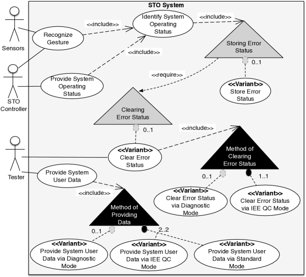
For use case diagrams, we employ the PL extensions proposed by Halmans and Pohl Halmans2003a ; Buhne2003 since they support explicit representation of variants, variation points, and their dependencies (see Fig. 1).
A use case is either Essential or Variant. Variant use cases are distinguished from essential use cases, i.e., mandatory for all the products in a product family, by using the stereotype Variant. A variation point given as a triangle is associated to one, or more than one use case using the relation include. A mandatory variation point indicates where the customer has to make a selection (the black triangles in Fig. 1). A ‘tree-like’ relation, containing a cardinality constraint, is used to express relations between variants and variation points, which are called variability relations. The relation uses a [min..max] notation in which and define the minimum and maximum numbers of variants that can be selected in the variation point.
| 1 | USE CASE Recognize Gesture |
| 2 | 1.1 Basic Flow (BF) |
| 3 | 1. The system REQUESTS move capacitance FROM the sensors. |
| 4 | 2. INCLUDE USE CASE Identify System Operating Status. |
| 5 | 3. The system VALIDATES THAT the operating status is valid. |
| 6 | 4. The system VALIDATES THAT the movement is a valid kick. |
| 7 | 5. The system SENDS the valid kick status TO the STO Controller. |
| 8 | 1.2 <OPTIONAL>Bounded Alternative Flow (BAF1) |
| 9 | RFS 1-4 |
| 10 | 1. IF voltage fluctuation is detected THEN |
| 11 | 2. ABORT. |
| 12 | 3. ENDIF |
| 13 | 1.3 Specific Alternative Flow (SAF1) |
| 14 | RFS 3 |
| 15 | 1. ABORT. |
| 16 | 1.4 Specific Alternative Flow (SAF2) |
| 17 | RFS 4 |
| 18 | 1. The system increments OveruseCounter by the increment step. |
| 19 | 2. ABORT. |
| 20 | |
| 21 | USE CASE Identify System Operating Status |
| 22 | 1.1 Basic Flow (BF) |
| 23 | 1. The system VALIDATES THAT the watchdog reset is valid. |
| 24 | 2. The system VALIDATES THAT the RAM is valid. |
| 25 | 3. The system VALIDATES THAT the sensors are valid. |
| 26 | 4. The system VALIDATES THAT there is no error detected. |
| 27 | 1.5 Specific Alternative Flow (SAF4) |
| 28 | RFS 4 |
| 29 | 1. INCLUDE <VARIATION POINT: Storing Error Status>. |
| 30 | 2. ABORT. |
| 31 | |
| 32 | USE CASE Provide System User Data |
| 33 | 1.1 Basic Flow (BF) |
| 34 | 1. The tester SENDS the system user data request TO the system. |
| 35 | 2. INCLUDE <VARIATION POINT : Method of Providing Data>. |
| 36 | |
| 37 | <VARIANT>USE CASE Provide System User Data via Standard Mode |
| 38 | 1.1 Basic Flow (BF) |
| 39 | V1. <OPTIONAL>The system SENDS calibration TO the tester. |
| 40 | V2. <OPTIONAL>The system SENDS sensor data TO the tester. |
| 41 | V3. <OPTIONAL>The system SENDS trace data TO the tester. |
| 42 | V4. <OPTIONAL>The system SENDS error data TO the tester. |
| 43 | V5. <OPTIONAL>The system SENDS error trace data TO the tester. |
A variability relation is optional where () or ( and ); n is the number of variants in a variation point. It is mandatory where (). Optional and mandatory relations are depicted with light-grey and black filled circles, respectively (see Fig. 1). For instance, the essential use case Provide System User Data has to support multiple methods of providing data where the methods of providing data via IEE QC mode and Standard mode are mandatory. In addition, the method of providing data via diagnostic mode can be selected. It can be decided that the STO system should not store the errors determined during the identification of the operating state (see the optional variation point Storing Error Status). The extensions support the dependencies require and conflict among variation points and variant use cases Buhne2003 . With require in Fig. 1, the selection of the variant use case in Storing Error Status implies the selection of the variant use case in Clearing Error Status.
2.1.2 Restricted Use Case Modeling (RUCM) with PL Extensions
This section introduces the RUCM (Restricted Use Case Modeling) template and its PL extensions which we proposed in our previous work Hajri2015 . RUCM is a use case modeling method with restriction rules and keywords constraining the use of NL Yue2013 . Since it was not designed for PL modeling, we introduced some PL extensions (see Table 1). In RUCM, use cases have basic and alternative flows (Lines 2, 8, 13, 16, 22, 27, 33 and 38). In Table 1, we omit some alternative flows and basic information such as actors and pre/post conditions.
A basic flow describes a main successful path that satisfies stakeholder interests (Lines 3-7, 23-26 and 39-43). It contains use case steps and a postcondition. A step can be a system-actor interaction: an actor sends a request or data to the system (Line 34); the system replies to an actor with a result (Line 7). In addition, the system validates a request or data (Line 5), or it alters its internal state (Line 18). Other use cases are included with the keyword ‘INCLUDE USE CASE’ (Line 4). The keywords are in capital letters. ‘VALIDATES THAT’ (Line 5) indicates a condition that must be true to take the next step, otherwise an alternative flow is taken.
An alternative flow describes other scenarios, both success and failure. It depends on a condition in a specific step in a flow of reference, referred to as reference flow, and that reference flow is either the basic flow or another alternative flow.
RUCM has specific, bounded and global alternative flows. A specific alternative flow refers to a step in a reference flow (Lines 13, 16, and 27). A bounded alternative flow refers to more than one step in a reference flow (Line 8), while a global flow refers to any step in a reference flow. ‘RFS’ is used to refer to reference flow steps (Lines 9, 14, 17, and 28). Bounded and global alternative flows begin with ‘IF .. THEN’ for the conditions under which they are taken (Line 10). Specific alternative flows do not necessarily begin with ‘IF .. THEN’ since a guard condition is already indicated in their reference flow steps (Line 5).
PUM extensions to RUCM include (i) new keywords for modeling interactions in embedded systems and (ii) new keywords for modeling variability. The keywords ‘SENDS .. TO’ and ‘REQUESTS .. FROM’ capture system-actor interactions (Lines 3, 7, 34, and 39-43). For instance, Step 1 (Line 3) indicates an input message from sensors to the system. For consistency with PL use case diagrams, PUM introduces into RUCM the notion of variation point and variant use case. Variation points can be included in basic or alternative flows with the keyword ‘INCLUDE <VARIATION POINT : … >’ (Lines 29 and 35). Variant use cases are given with the keyword ‘<VARIANT >’ (Line 37). To capture variability that cannot be modeled in use case diagrams because of their coarse granularity, PUM introduces optional steps, optional alternative flows and a variant order of steps. Optional steps and alternative flows begin with the keyword ‘<OPTIONAL>’ (Lines 8 and 39-43). The keyword ‘V’ is used before step numbers to express variant step order (Lines 39-43). A variant order occurs with optional and/or mandatory steps. For instance, the steps in the basic flow of Provide System User Data via Standard Mode are optional, while their execution order varies.
2.2 Configuration of PS Use Case Models
PUMConf supports users in making configuration decisions and automatically generating PS use cases from PL use cases.
The user selects (1) variant use cases in the PL use case diagram and (2) optional use case elements in the PL use case specifications, to generate PS use case diagram and specifications. For instance, the user makes decisions for the variation points in Fig. 1. A decision is about selecting, for the product, variant use cases in the variation point. The user selects Store Error Status and Clear Error Status in the variation points Storing Error Status and Clearing Error Status, respectively. She also unselects Clear Error Status via Diagnostic Mode in the variation point Method of Clearing Error Status, while Clear Error Status via IEE QC Mode is automatically selected by PUMConf because of the mandatory variability relation. Finally, the user unselects Provide System User Data via Diagnostic Mode in the variation point Method of Providing Data.
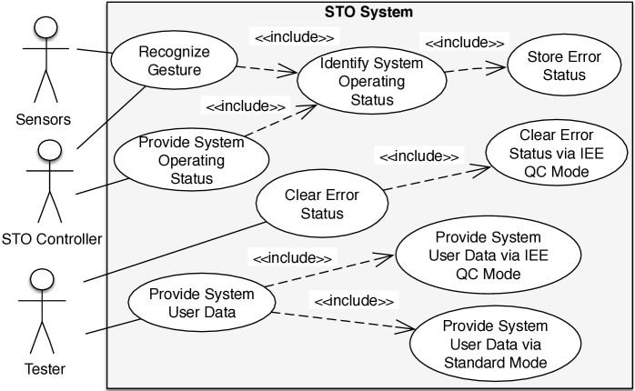
Given the configuration decisions, PUMConf automatically generates the PS use case diagram from the PL diagram (see Fig. 2 generated from Fig. 1). For instance, for the decision for the variation point Method of Providing Data, PUMConf creates the use cases Provide System User Data via IEE QC Mode and Provide System User Data via Standard Mode, and two include relations in Fig. 2.
| 1 | USE CASE Recognize Gesture |
| 2 | 1.1 Basic Flow (BF) |
| 3 | 1. The system REQUESTS the move capacitance FROM the sensors. |
| 4 | 2. INCLUDE USE CASE Identify System Operating Status. |
| 5 | 3. The system VALIDATES THAT the operating status is valid. |
| 6 | 4. The system VALIDATES THAT the movement is a valid kick. |
| 7 | 5. The system SENDS the valid kick status TO the STO Controller. |
| 8 | 1.2 Specific Alternative Flow (SAF1) |
| 9 | RFS 3 |
| 10 | 1. ABORT. |
| 11 | 1.3 Specific Alternative Flow (SAF2) |
| 12 | RFS 4 |
| 13 | 1. The system increments the OveruseCounter by the increment step. |
| 14 | 2. ABORT. |
| 15 | |
| 16 | USE CASE Identify System Operating Status |
| 17 | 1.1 Basic Flow (BF) |
| 18 | 1. The system VALIDATES THAT the watchdog reset is valid. |
| 19 | 2. The system VALIDATES THAT the RAM is valid. |
| 20 | 3. The system VALIDATES THAT the sensors are valid. |
| 21 | 4. The system VALIDATES THAT there is no error detected. |
| 22 | 1.5 Specific Alternative Flow (SAF4) |
| 23 | RFS 4 |
| 24 | 1. INCLUDE USE CASE Store Error Status. |
| 25 | 2. ABORT. |
| 26 | |
| 27 | USE CASE Provide System User Data |
| 28 | 1.1 Basic Flow (BF) |
| 29 | 1. The tester SENDS the system user data request TO the system. |
| 30 | 2. The system VALIDATES THAT ‘Precondition of Provide System User Data via Standard Mode’. |
| 31 | 3. INCLUDE USE CASE Provide System User Data via Standard Mode. |
| 32 | 1.2 Specific Alternative Flow (SAF1) |
| 33 | RFS 2 |
| 34 | 1. INCLUDE USE CASE Provide System User Data via IEE QC Mode. |
| 35 | 2. ABORT. |
| 36 | |
| 37 | USE CASE Provide System User Data via Standard Mode |
| 38 | 1.1 Basic Flow (BF) |
| 39 | 1. The system SENDS the trace data TO the tester. |
| 40 | 2. The system SENDS the calibration data TO the tester. |
| 41 | 3. The system SENDS the error trace data TO the tester. |
After identifying variant use cases to be included in the PS diagram, the user makes decisions based on the PL specifications. In Table 1, there are two variation points (Lines 29 and 35), one variant use case (Lines 37-43), five optional steps (Lines 39-43), one optional alternative flow (Lines 8-12), and one variant order group (Lines 39-43). The decisions for the variation points are already made in the PL diagram. Three optional steps are selected with the order V3, V1, and V5. The optional alternative flow is unselected.
PUMConf automatically generates PS use case specifications from PL specifications, diagram decisions and specification decisions. Table 2 shows a PS use case specification generated from Table 1, where selected optional steps are generated with the order decided in the PS specifications (Lines 39-41). For multiple variants selected for the same variation point, PUM introduces validation checks to select the variation point to be used, based on their preconditions. For instance, based on the diagram decision for Method of Providing Data in Fig. 1, PUMConf creates two include statements for Provide System User Data via Standard Mode and via IEE QC Mode (Lines 31 and 34 in Table 2), and a validation step (Line 30) that checks if the precondition of Provide System User Data via Standard Mode holds. If it holds, Provide System User Data via Standard Mode is executed in the basic flow (Line 31). If not, Provide System User Data via IEE QC Mode is executed (Lines 32-35).
2.3 Glossary
An actor specifies a type of role played by an entity interacting with the system (e.g., by exchanging signals and data), but which is external to the system (see Section 2.1).
A use case is a list of actions or event steps typically defining the interactions between an actor and a system to achieve a goal. It is generally named with a phrase that summarizes the story description, e.g., Recognize Gesture (see Section 2.1).
A use case specification is a textual document that captures the specific details of a use case. Use case specifications provide a way to document the functional requirements of a system. They generally follow a template (see Section 2.1).
A use case scenario model is a graph representation of a use case specification (see Section 5.2.1).
A use case flow is a sequence of interactions between actors and the system captured by a use case specification. A use case specification may include multiple alternative use case flows (see Section 2.1).
A use case scenario is a sequence of interactions between actors and the system. It represents a single use case execution. It is a possible path through a use case specification. It may include multiple use case flows (see Section 5.2.1).
A finite state machine is an abstract machine, i.e., a theoretical model of a system used in automata theory, that can be in exactly one of a finite number of states at any given time (see Section 3).
A sequence diagram shows interactions between objects in a sequential order, i.e., the order in which these interactions take place (see Section 3).
A system sequence diagram (SSD) is a sequence diagram that shows, for a particular scenario of a use case, the events that actors generate, their order, and possible inter-system events (see Section 3).
Model slicing allows for a model reduction by abstracting from model elements not influencing a selected element, e.g., a state transition, used as a slicing criterion (see Section 3). A reduced model is a slice that preserves the execution semantics compared to the original model with respect to the slicing criterion.
Fault proneness of requirements allows engineers to identify the requirements which have had reported failures (see Sections 3, 4 and 6). As the system evolves into several versions, engineers can use the data collected from prior versions to identify requirements that are likely to be error prone Srikanth2005 .
Requirements volatility is a measure of how much a system’s requirements change during the development of the system (see Sections 3 and 4). Projects for which the requirements change greatly have a high volatility, while projects whose requirements are relatively stable have a low volatility Malaiya1999 ; Henry93 .
A single-product setting is an experiment setting where the new product is compared to only one previous product in the product line at once (see Section 8). Assume that there are previous products (, , …, and ) in a product line. In a single-product setting, the new product () is compared to each previous product distinctly at times ( - , - , …, - ).
A whole-line setting is an experiment setting where the new product is compared to all the previous products in the product line at once (see Section 8). In a whole-line setting, the new product () is compared to all the previous products at the same time ( - , , …, ).
3 Related Work
We cover the related work across three categories: (i) testing of product lines, (ii) test case classification and selection, and (iii) test case prioritization. The last two categories cover the features our approach addresses in the context of product lines. In the first category, we present existing product line testing strategies and discuss how our approach is related to specific testing strategies and activities such as test case generation and execution.
3.1 Testing of Product Lines
Various product line testing strategies have been proposed in the literature do2014strategies ; Neto2011 ; Lee-SPLTestingSurvey-SPLC-2012 ; Engstrom2011 ; Runeson2012 ; oster2011survey ; tevanlinna2004product ; johansen2011survey . Neto et al. Neto2011 present a comprehensive survey, including testing product by product, opportunistic reuse of test assets, design test assets for reuse, division of responsibilities, and incremental testing of product lines. The strategy testing product by product does not attempt to reuse test cases developed for previous products, while the strategy opportunistic reuse of test assets focuses on the reuse of test assets across products without considering any systematic reuse method. The strategy design test assets for reuse enforces the creation of test assets early in product line development, under the assumption that product lines and configuration choices are exhaustively modeled before the release of any product. This assumption does not hold when product lines and configuration choices are refined during product configuration, which is a common industry practice. The strategy division of responsibilities is about defining testing phases that facilitate test reuse. Our approach follows the strategy referred to as incremental testing of product lines, which relies on regression testing techniques, i.e., test case selection and prioritization. We are the first to support incremental testing of product lines through test case selection and prioritization in the context of use case-driven development.
Product line testing covers two separate but closely related test engineering activities: domain testing and application testing. Domain testing verifies and validates reusable components in a product line while application testing does so for a specific product in the product line. Domain test cases can be created either directly from domain artifacts or through domain test models (derived from domain artifacts). Application test cases can be created directly from domain test cases by using variability binding information in products. A test case can be executed before or after variability binding in products, and the variability binding can occur during the development phase, at compile time, or at runtime. Our approach currently supports application testing, but can be adapted to classify domain test cases. More specifically, the scenario generation and impact analysis algorithms in Section 5.2.4 can be adapted to identify scenarios of the variant requirements and eventually to determine test cases examining those scenarios. For each new product, our approach can be used to classify and prioritize domain test cases derived from PL use case models.
There are various product line testing approaches that support test case generation and execution (e.g., Nebut06 ; Reuys2006 ; Kamsties2004 ; Geppert2004 ; Uzuncaova2010 ; Uzuncaova2008 ; Arrieta2017 ). Some of them generate system test cases from use case models in a product family. However, they require detailed behavioral models (e.g., sequence or activity diagrams) which engineers tend to avoid because of the costs related to their development and maintenance. Among these works generating system test cases from use cases, the ScenTED approach proposed by Reuys et al. Reuys2005 ; Reuys2006 is a representative approach in terms of its reliance on behavioral models for test case generation and execution in product lines. It is based on the systematic refinement of PL use case scenarios to PL system and integration test scenarios. ScenTED requires activity diagrams capturing activities described in use case specifications together with variants of the product family. Extensions of ScenTED include the ScenTED-DF approach Stricker2010 which relies on data-flow analysis to avoid redundant execution of test cases derived with ScenTED. A methodology that does not rely on detailed behavioral models is PLUTO (Product Lines Use Case Test Optimization) Bertolino2003 . PLUTO automatically derives test scenarios from PL use cases with some special tags for variability, but executable system test cases need to be manually derived from test scenarios.
This paper complements the approaches above by providing a mechanism for selecting and prioritizing test cases, that have already been generated and executed in previous products.
3.2 Test Case Classification and Selection
When defining a product in a product family for a new customer, the changed parts of the new product need to be tested, as well as the other parts to detect regression faults. In most practical contexts, given the number of test cases and their execution time, not all of them can be rerun for regression due to limited resources. Test case selection is a strategy commonly adopted by regression testing techniques to reduce testing costs Engstrom2010 ; Yoo2012 ; Do2016 . Therefore, we investigate test case classification and selection approaches under two categories: (i) the selection of regression test cases for a single product and (ii) the selection of test cases for each product in a product line.
Regression test selection techniques aim to reduce testing costs by selecting a subset of test cases from an existing test suite Rothermel1996 . Most of them are code-based and use code changes and code coverage information to guide test selection (e.g., Kung1995 ; Binkley1997 ; Rothermel1997 ; Rothermel2000 ; Harrold2001 ; Qu2011 ; Nardo2015 ). Other techniques use different artifacts such as requirements specifications (e.g., Vaysburg2002 ; Mirarab2008 ; Dukaczewski2013 ), architecture models (e.g., Mayrhauser1999 ; Muccini2006 ; Muccini2007 ), or UML diagrams (e.g., Briand2009 ; Chen2002 ; Hemmati2010 ). For instance, Briand et al. Briand2009 present an approach for automating regression test selection based on UML diagrams and traceability information linking UML models to test cases. They propose a formal mapping between changes on UML diagrams (i.e., class and sequence diagrams) and a classification of regression test cases into three categories (i.e., reusable, retestable, and obsolete).
The approaches mentioned above require detailed design artifacts (e.g., finite state machines and sequence diagrams), rather than requirements in NL, such as use case specifications. Further, they compare a system artifact with its modified version to select test cases from a test suite in the context of a single system, not in the context of a product line.
There are several product line test case selection approaches Wang2016 ; Wang2017 ; Cabral2010 ; Knapp2014 ; Schurr2010 ; Runeson2012 ; Engstrom2013 . Wang et al. Wang2016 ; Wang2017 propose a product line test case selection method using feature models. The method works in three steps: (i) software engineers indicate features that need to be tested; (ii) a toolset is used to check the consistency between features included in a program; and (iii) test cases are automatically selected so that all the test cases associated with a feature to be tested will be executed. The main limitation is that all the test cases of the product family need to be derived upfront and that the scope of the product family must be defined in advance. There are other similar approaches suffering from the same limitation Cabral2010 ; Knapp2014 ; Schurr2010 . In contrast, our approach requires that only test cases for the initial product be available in advance. A test case selection approach that does not require early generation of test cases for the product family is that of Lity et al. Lity2016 ; Lochau2014 ; Lity2012 , which is based on model slicing for incremental product line testing. Lity et al. apply incremental model slicing to determine the impact of changes on a test model, e.g., finite state machines, and to reason about their potential retest. The approach first computes test model regression deltas between the previous and new products. Based on a structural coverage criterion and the computed regression deltas, a set of impacted test goals, i.e., structural test model elements, is identified from the test model. The impacted test goals are analyzed to identify obsolete test cases for the new product. For each product, the approach computes a test model slice, which comprises test model elements influencing a test goal based on control and data dependencies between elements. Reusable and retestable test cases are identified based on the changes between the test model slices of the previous and new products. The approach needs detailed behavioral models, e.g., finite state machines and message sequence diagrams, which rarely exist in contexts where requirements are mostly captured in NL. In complex industrial systems, behavioral models that are precise enough to enable test case selection are so complex that their specification cost is prohibitive and the task is often perceived as overwhelming by engineers. In contrast, our approach does not require that detailed behavioral models be provided by engineers. With the help of NLP, it automatically extracts behavioral information from use case specifications compliant with RUCM (see Sections 5.2.1 and 5.2.2). Lity et al. do not address how to trace from impacted test goals to their corresponding test cases while our approach provides a detailed traceability method required for test case classification (see Section 5.2.3). We automatically identify all tested use case scenarios and derive new, untested scenarios from the tested scenarios (see Sections 5.2.2 and 5.2.3). To classify test cases, we directly identify the impact of configuration decision changes on the tested scenarios. Therefore, in contrast to the work by Lity et al., our approach does not need model slices and a retest coverage criterion, i.e., a structural coverage criterion, for the retest decision. In addition, Lity et al. do not support the definition of test cases for new requirements while our approach identifies use case scenarios that have not been tested before, and provides information on how to modify existing test cases to cover those new, untested scenarios (see Section 5.2.4). Dukaczewski et al. Dukaczewski2013 briefly discuss how to apply the incremental product line testing strategy to NL requirements. They do not provide any method to model variability in requirements; it is only suggested that a requirement is split into several requirements, one for each possible product variant. Also, there is no reported systematic approach supported by a tool. To the best of our knowledge, our work is the first systematic and automated approach for supporting the incremental product line testing strategy for NL requirements.
3.3 Test Case Prioritization
Test case prioritization techniques schedule test cases in an order that increases their effectiveness in meeting some performance goals (e.g., rate of fault detection and number of test cases required to discover all the faults) Rothermel2001 ; Khatibsyarbini2017 ; Yoo2012 . They mostly use information about previous executions of test cases (e.g., Rothermel2001 ; Li2007 ; Engstrom2011b ; Sanchez2011 ; Lachmann2016b ; Hemmati2017 ), human knowledge (e.g., Srikanth2014 ; Srikanth2016 ; Srikanth2012 ; Arafeen2013 ; Krishnamoorthi2009 ; Tonella2006 ), or a model of the system under test (e.g., Haidry2013 ; Kundu2009 ; Tahat2012 ; Korel2008 ). For instance, Shrikanth et al. Srikanth2005 propose a test case prioritization approach that takes into consideration customer-assigned priorities of requirements, developer-perceived implementation complexity, requirements volatility, and fault proneness of requirements. Tonella et al. Tonella2006 propose a test case prioritization technique using user knowledge through a machine learning algorithm (i.e., Case-Based Ranking). Lachmann et al. Lachmann2016b propose another test case prioritization technique for system-level regression testing based on supervised machine learning. They consider test case history and natural language test case descriptions for prioritization. Since they consider the next version of a single system, their approach does not take into account variability and the classification of test cases in a product line for test case prioritization. In contrast to the aforementioned approaches, we do aim at prioritizing test cases for a new product in a product family, not for the next version of a single system. Our approach considers multiple factors (i.e., test execution history, requirements variability, the classification of test cases and the size of scenarios exercised by test cases) in a product line, identifies their impact on the test case prioritization for the previous products in the product line, and prioritizes test cases for a new product accordingly.
There are approaches that address test case prioritization in product lines (e.g., Runeson2012 ; Engstrom2013 ; Hajiaji2014 ; Hajjaji2017 ; Baller2014 ; Henard2014 ; Ensan2011 ; Devroey2017 ; Devroey2014 ; Hajjaji2017c ; Hajjaji2017b ; Lity2017 ). For instance, to increase feature interaction coverage during product-by-product testing, similarity-based prioritization techniques incrementally select the most diverse products in terms of features to be tested Henard2014 ; Hajiaji2014 ; Hajjaji2017 . Baller et al. Baller2014 propose an approach to prioritize products in a product family based on the selection of test suites with regard to cost/profit objectives. The aforementioned techniques prioritize the products to be tested, which is not useful in our context since products are seldom developed in parallel. In contrast, our approach prioritizes the test cases of a new product to support early detection of software faults based on multiple risk factors.
There are search-based approaches for multi-objective test case prioritization in product lines (e.g., Wang2014 ; Parejo2016 ; Arrieta2016 ; Arrieta2019 ). For instance, Parejo et al. Parejo2016 model test case prioritization as a multi-objective optimization problem and implement a search-based algorithm to solve it based on the NSGA-II evolutionary algorithm. Arrieta et al. Arrieta2019 propose another approach that cost-effectively optimizes product line test process. None of them work based on information at the level of NL requirements.
| No need for behavioral models or source code for test case selection | Support for PL test case selection | No need to derive upfront all the test cases of PL for test case selection | No need for behavioral models or code for test case prioritization | Support for PL test case/product prioritization | Support for prioritizing test cases in PL, not products in PL | |
| Our Approach | ||||||
| Wang et al. Wang2016 ; Wang2017 | ||||||
| Cabral et al. Cabral2010 | ||||||
| Knapp et al. Knapp2014 | ||||||
| Schurr et al. Schurr2010 | ||||||
| Briand et al. Briand2009 | ||||||
| Hemmati et al. Hemmati2010 | ||||||
| Rothermel et al. Rothermel2000 | ||||||
| Rothermel et al. Rothermel1997 | ||||||
| Binkley Binkley1997 | ||||||
| Harrold et al. Harrold2001 | ||||||
| Qu et al. Qu2011 | ||||||
| Kung et al. Kung1995 | ||||||
| Muccini et al. Muccini2006 | ||||||
| Vaysburg et al. Vaysburg2002 | ||||||
| Mirarab et al. Mirarab2008 | ||||||
| Lity et al. Lity2016 ; Lochau2014 ; Lity2012 | ||||||
| Lachmann et al. Lachmann2015 | ||||||
| Lachmann et al. Lachmann2016 | ||||||
| Lachmann et al. Lachmann2017 | ||||||
| Henard et al. Henard2014 | ||||||
| Al-Hajiaji et al. Hajiaji2014 ; Hajjaji2017 | ||||||
| Baller et al. Baller2014 | ||||||
| Shrikanth et al. Srikanth2005 ; Srikanth2012 | ||||||
| Tonella et al. Tonella2006 | ||||||
| Lachmann et al. Lachmann2016b | ||||||
| Sanchez et al. Sanchez2011 | ||||||
| Hemmati et al. Hemmati2017 | ||||||
| Lachmann et al. Lachmann2016b | ||||||
| Krishnamoorthi et al. Krishnamoorthi2009 | ||||||
| Arafeen et al. Arafeen2013 | ||||||
| Haidry and Miller Haidry2013 | ||||||
| Korel et al. Korel2008 | ||||||
| Kundu et al. Kundu2009 | ||||||
| Tahat et al. Tahat2012 |
Lachmann et al. Lachmann2015 introduce a test case prioritization technique for product lines using delta-oriented architecture models. The differences between products are captured in the form of deltas Clarke2010 , which are modifications between architecture models of products used for integration testing. The proposed approach ranks test cases based on the number of changed elements in the architecture. The approach first identifies the regression deltas specifying the differences between architecture models. For every product, it creates a delta graph, which is later used to compute the degree of changes between the current product under test and the previously tested products. To prioritize test cases, the approach computes the change of each architecture component using the delta graph of the current product under test. The higher the corresponding change, the more likely is the test case to fail. The approach is later extended using risk factors Lachmann2017 and behavioral knowledge of architecture components Lachmann2016 . The approach proposed by Lachmann et al. requires access to product architecture descriptions and information about component behavior. In contrast, we do not require any design information but rely on NL requirements specifications, i.e., use case specifications. Our approach does not need to identify any regression delta between requirements of previous and current products. We, instead, rely on logistic regression models that use variability information in PL use case models, the classification of test cases, test execution history and test scenario characteristics. Compared to the delta-oriented approach, we rely on textual requirements and test case execution history without requiring detailed design models, which rarely exist in industrial settings. For instance, IEE does not produce the detailed design models that the delta-oriented approach requires to prioritize test cases for product lines. Therefore, we expect our approach to be more widely applicable in industrial settings.
In Table 3, based on a set of features necessary for the selection and prioritization of system test cases in product lines, we summarize the differences between our approach and the closest related work. For each approach, the symbol ’+’ indicates that the approach provides a feature, the symbol ’-’ indicates that it does not do so, and ’NA’ indicates that the feature is out of scope. For instance, the approach by Lachmann et al. Lachmann2016b automatically prioritizes system test cases, but does not classify test cases. Therefore, all the features related to the classification of system test cases are not considered for Lachmann et al. Lachmann2016b in Table 3. Some of the existing test case selection approaches do not support product lines Binkley1997 ; Rothermel1997 ; Rothermel2000 ; Vaysburg2002 ; Mirarab2008 ; Muccini2006 . The approaches that support product lines need either detailed behavioral models Lity2016 ; Lochau2014 ; Lity2012 or must derive upfront all the test cases of a product line Wang2016 ; Wang2017 ; Cabral2010 ; Knapp2014 ; Schurr2010 . On the other hand, PL prioritization approaches either need detailed behavioral models Lachmann2015 ; Lachmann2017 ; Lachmann2016 or prioritize products in a product line, not system test cases Henard2014 ; Hajiaji2014 ; Hajjaji2017 ; Baller2014 . Our approach is currently the only approach that automatically classifies and prioritizes system test cases in PL without requiring neither behavioral models nor the upfront provision of all test cases. This is enabled by the capability of automatically analyzing system requirements in NL in the form of use case specifications.
There is work using industrial cases studies to evaluate their PL test case classification and prioritisation techniques. However, our work is driven by current practice and its limitations, together with working assumptions, in a specific domain that was not addressed by existing work: use case driven development of embedded, safety-critical systems.
4 Overview of the Approach
The process in Fig. 3 presents an overview of our approach. In Step 1, Classify system test cases for the new product, our approach takes as input (i) system test cases, PS use case models, their traceability links, and configuration decisions for previous products in the product family, and (ii) PS use case models and configuration decisions for the new product, to classify the system test cases for the new product as obsolete, retestable, and reusable, and to provide information on how to modify obsolete system test cases to cover new, untested use case scenarios.
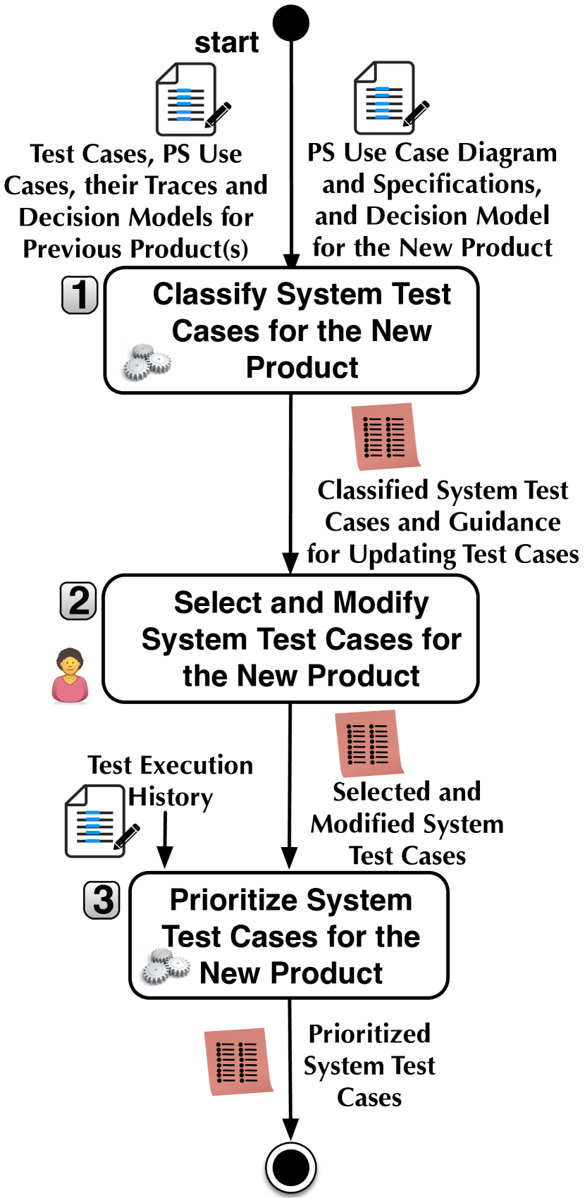
Step 1 is fully-automated. The classification and modification information in output of this step is for the test engineer to decide which test cases to execute for the new product and which modifications to make on the obsolete test cases to cover untested, new use case scenarios. We give the details of this step in Section 5.
In Step 2, Select and modify system test cases for the new product, by using the classification information and modification guidelines automatically provided by our approach, the engineer decides which test cases to run for the new product and modifies obsolete test cases to cover untested, new use case scenarios. The activity is not automated because, for the selection of system test cases, the engineer may also need to consider implementation and hardware changes (e.g., code refactoring and replacing some hardware with less expensive technology) in addition to the classification information provided in Step 2, which is purely based on changes in functional requirements. For instance, a reusable test case might need to be rerun because part of the source code verified by the test case is refactored.
In Step 3, Prioritize system test cases for the new product, selected test cases are automatically prioritized based on risk factors including fault proneness of requirements, and requirements volatility. We discuss this step in Section 6.
5 Classification of System Test Cases
The test case classification is implemented as a pipeline (see Fig. 4), which takes as input the configuration decisions made for the previous products, the configuration decisions made for the new product, and the previous product’s system test cases, traceability links, and PS use case models. The pipeline produces an impact report with the list of existing test cases classified.
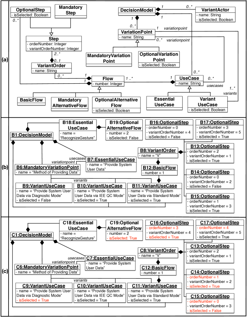
Configuration decisions are captured in a decision model that is automatically generated by PUMConf during the configuration process. The decision model conforms to a decision metamodel described in our previous work Hajri2016c . The metamodel includes the main use case elements for which the user makes decisions (i.e., variation points, optional steps, optional alternative flows, and variant orders). PUMConf keeps a decision model for each configuration in the product line. Fig. 5 provides the decision metamodel and two decision models for the PL use case models in Fig. 1 and Table 1.
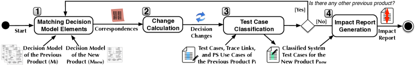
The pipeline has four steps (see Fig. 4). The first three steps are executed for each of the previous products in the product line, where each one has a decision model with . Note that we also employ the first two steps of the pipeline in our previous work Hajri2018 ; Hajri2017a . In Step 1, Matching decision model elements, our approach automatically executes the structural differencing of and by looking for corresponding model elements representing decisions for the same variations (see Section 5.1).
| Change Types |
|---|
| . Add a decision |
| . Delete a decision |
| . Update a decision |
| - Select some unselected variant element(s) |
| - Unselect some selected variant element(s) |
| - Unselect some selected variant element(s) and select some unselected variant element(s) |
| - Change order number of variant step order(s) |
In Step 2, Change calculation, the approach determines how configuration decisions of the two products differ. Table 4 lists the types of decision changes. A decision is represented by means of a n-tuple of model elements in a decision model, e.g., variation point VP, use case UC including VP. A change is of type “Add a decision” when a tuple representing a decision in has no matching tuple in . A change is of type “Delete a decision” when a tuple representing a decision in has no matching tuple in . A change is of type “Update a Decision” when a tuple representing a decision in has a matching tuple in with non-identical attribute values (see the red-colored attributes in Fig. 5(c)).
In Step 3, Test case classification, the system test cases of the previous products are classified for the new product by using the decision changes obtained from Step 2 and the traceability links between the system test cases and the PS use case specifications (see Section 5.2). A use case can describe multiple use case scenarios (i.e., sequences of use case steps from the start to the termination of the use case) because of the presence of conditional steps. Each system test case is expected to exercise one use case scenario. For each use case of the new product, we identify the impact of the decision change(s) on the use case scenarios, i.e., any change in the execution sequence of the use case steps in the scenario.
A system test case is classified in one of three categories: obsolete, retestable and reusable. A test case is obsolete if it exercises an invalid execution sequence of use case steps in the new product. A test case is retestable if it exercises an execution sequence of use case steps that has remained valid in the new product, except for internal steps representing internal system operations (e.g., reset of counters). A test case is reusable if it exercises an execution sequence of use case steps that has remained valid in the new product. The test case categories are mutually exclusive. Use case scenarios of the new product that have not been tested for the previous product are reported as new use case scenarios.
In Step 4, Impact report generation, we automatically generate an impact report from the classified test cases of each previous product to enable engineers to select test cases from more than one test suite (see Section 5.3). Steps 1, 2 and 3 are the pairwise comparison of each previous product with the new product. If there are multiple previous products ( in Fig. 4), test cases of each product are classified separately in reports in Step 3. The generated impact report compares these separate reports and lists sets of new scenarios and reusable and retestable test cases for the previous products.
5.1 Steps 1 and 2: Model Matching and Change Calculation
For the first two pipeline steps in Fig. 4, we rely on a model matching and change calculation algorithm we devised in our prior work Hajri2017a ; Hajri2018 . In this section, we provide a brief overview of the two steps and their output for the example decision models in Fig. 5(b) and (c).
| Decisions in | Decisions in |
|---|---|
| <B6, B7 > | <C6, C7 > |
| <B18, B19 > | <C18, C19 > |
| <B11, B12, B13 > | <C11, C12, C13 > |
| <B11, B12, B14 > | <C11, C12, C14 > |
| <B11, B12, B15 > | <C11, C12, C15 > |
| <B11, B12, B16 > | <C11, C12, C16 > |
| <B11, B12, B17 > | <C11, C12, C17 > |
In Step 1, we identify pairs of decisions in and that are made for the same variants. The decision metamodel in Fig. 5(a) includes the main use case elements for which the user makes decisions (i.e., variation point, optional step, optional alternative flow, and variant order). In a variation point included by a use case222In PL use case diagrams, use cases are connected to variation points with an include dependency., the user selects variant use cases to be included for the product. For PL use case specifications, the user selects optional steps and alternative flows to be included and determines the order of steps (variant order). Therefore, the matching decisions in Step 1 are (i) the pairs of variation points and use cases including the variation points, (ii) the pairs of use cases and optional alternative flows in the use cases, and (iii) the triples of use cases, flows in the use cases, and optional steps in the flows. Table 5 shows some decisions in Fig. 5(b) and (c). For example, the pairs and represent two decisions for the variation point Method of Providing Data included in the use case Provide System User Data. The triples and represent two decisions for an optional step in the basic flow of the use case Provide System User Data via Standard Mode (i.e., for V2 in Line 40 in Table 1).
In Step 2, Change Calculation, we first identify deleted and added configuration decisions by checking tuples of model elements in one input decision model () which do not have any matching tuples of model elements in another input decision model (). To identify updated decisions, we check tuples of model elements in that have matching tuples of model elements in with non-identical attribute values. The matching pairs of variation points and their including use cases represent decisions for the same variation point (e.g., and in Table 5). If the selected variant use cases for the same variation point are not the same in and , the decision in is considered as updated in . We have similar checks for optional steps, optional alternative flows and variant order of steps. For instance, an optional step is selected in the decision represented by the triple in , while the same optional step is unselected in the decision represented by the matching triple in . For the decision models in Fig. 5, the decisions represented by , , , , , and are identified as updated. There are no deleted or added decisions for the models in Fig. 5.
5.2 Step 3: Test Case Classification
System test cases of the previous product are automatically classified based on the identified changes (Step 3 in Fig. 4). To this end, we devise an algorithm (see Fig. 6) which takes as input a set of use cases (UC), the test suite of the previous product (ts), and a triple of the sets of configuration changes (dc) detected in Step 2. It classifies the test cases and reports use case scenarios of the new product that are not present in the previous product.
| Input: Set of use case specifications of the previous product , | |
| Test suite of the previous product , | |
| Triple of sets of decision-level changes | |
| (ADD, DELETE, UPDATE) | |
| Output: Quadruple of sets of classified test cases | |
| 1. | Let be the empty set for obsolete test cases | |||
| 2. | Let be the empty set for reusable test cases | |||
| 3. | Let be the empty set for retestable test cases | |||
| 4. | Let be the empty set for new use case scenarios | |||
| 5. | Let be the quadruple (OBSOLETE, REUSE, RETEST, NEW) | |||
| 6. | foreach do | |||
| 7. | if (there is a change in for ) then | |||
| 8. | generateUseCaseModel() | |||
| 9. | Let be a new version of after the changes in | |||
| 10. | identifyTestedScenarios(, ) | |||
| 11. | foreach do | |||
| 12. | retrieveTestCases(, , ) | |||
| 13. | analyzeImpact(, , , ) | |||
| 14. | end foreach | |||
| 15. | else | |||
| 16. | retrieveTestCases(, ) | |||
| 17. | end if | |||
| 18. | end foreach | |||
| 19. | filterNewScenarios() | |||
| 20. |
For each use case in the previous product, we check whether it is impacted by some configuration changes (Lines 6-7 in Fig. 6). If there is no impact, all the system test cases of the use case are classified as reusable (Lines 15-17); otherwise, we rely on the function generateUseCaseModel (Line 8) to generate a use case model, i.e., a model that captures the control flow in the use case. This model is used to identify scenarios that have been tested by one or more test cases (identifyTestedScenarios in Line 10). For each scenario verified by a test case (retrieveTestCases in Line 12), we rely on the function analyzeImpact (Line 13) to determine how decision changes affect the behaviour of the scenario.
In Sections 5.2.1, 5.2.2, 5.2.3 and 5.2.4, we give the details of the functions generateUseCaseModel, identifyTestedScenarios, retrieveTestCases and analyzeImpact, respectively.
5.2.1 Use Case Model Generation
To generate a use case scenario model from a PS use case specification, we rely on a Natural Language Processing (NLP) solution proposed by Wang et al. Wang2015a . It relies on the RUCM keywords and part-of-speech tagging to extract information required to build a use case model. In this section, we briefly describe the metamodel for use case scenario models, shown in Fig. 7, and provide an overview of the model generation process. UseCaseStart represents the beginning of a use case with a precondition and is linked to the first Step (i.e., next in Fig. 7). There are two Step subtypes, i.e., Sequence and Condition. Sequence has a single successor, while Condition has two successors (i.e., true and false in Fig. 7).
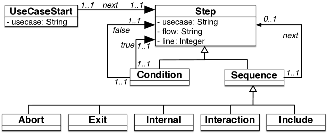
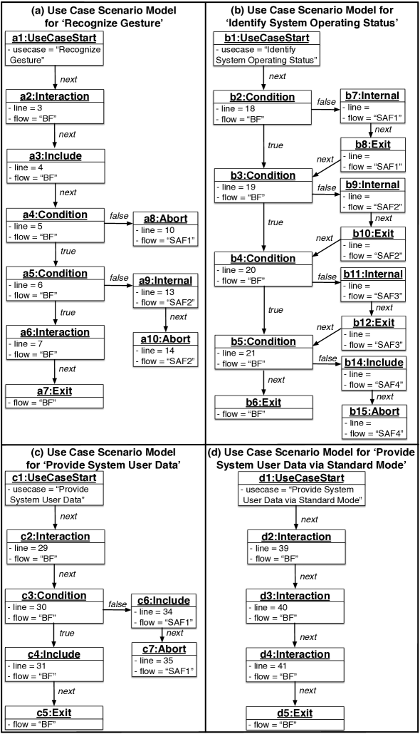
Interaction indicates the invocation of an input/output operation between the system and an actor. Internal indicates that the system alters its internal state. Exit represents the end of a use case flow, while Abort represents the termination of an anomalous execution flow. Fig. 8 shows the models generated from the use cases in Table 2. For each Interaction, Include, Internal, Condition and Exit step, a Step instance is generated and linked to the previous Step instance.
For each alternative flow, a Condition instance is created and linked to the Step instance of the first step of the alternative flow (e.g., a4 and a5 in Fig. 8(a)). For multiple alternative flows on the same condition, Condition instances are linked to each other in the order they follow in the specification. For alternative flows that return back to the reference flow, an Exit instance is linked to the Step instance that represents the reference flow step (e.g., next between b8 and b3 in Fig. 8(b)).
5.2.2 Identification of Tested Use Case Scenarios
We automatically identify tested use case scenarios in a use case specification. A scenario is a sequence of steps that begins with a UseCaseStart instance and ends with an Exit instance in the use case model. Each use case scenario captures a set of interactions that should be exercised during the execution of a test case. The function identifyTestedScenarios (see Line 12 in Fig. 6) implements a depth-first traversal of use case models to identify tested scenarios. It visits alternative flows which are tested together with previously visited alternative flows by the same test case.
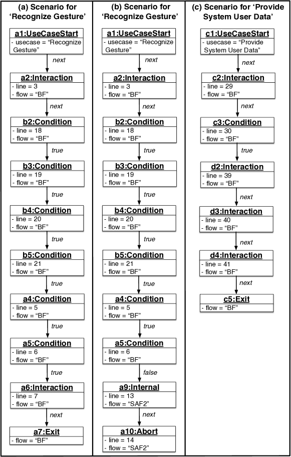
Fig. 9 shows three tested scenarios extracted from the scenario models in Fig. 8(a) and (c). The scenario in Fig. 9(a) executes the true branch of the Condition instance a5 in Fig. 8(a), while the scenario in Fig. 9(b) executes the false branch of the same instance. The scenario in Fig. 9(c) executes the basic flows in Fig. 8(c) and (d).
5.2.3 Identification of Test Cases for Use Case Scenarios
We use traceability links between test cases and use case specifications to retrieve test cases for a given scenario. The accuracy of test case retrieval depends on the granularity of traceability links. Companies may follow various traceability strategies Ramesh:2001aa , and generate links in a broad range of granularity (e.g., to use cases, to use case flows or to use case steps). We implement a traceability metamodel which enables the user to generate traceability links at different levels of granularity (see Fig. 10(a)).
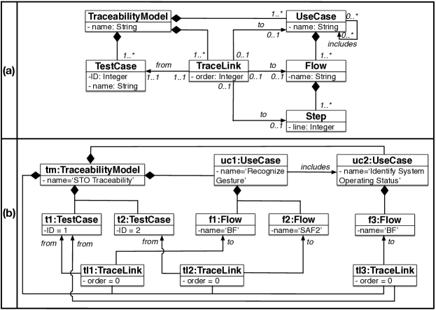
Fig. 10 (b) gives part of the traceability model for traceability links, assigned by engineers, between two test cases and the use cases Recognize Gesture and Identify System Operating Status in Table 2. Test case t1 is traced to the basic flows of Recognize Gesture and Identify System Operating Status (i.e., (t1 f1) and (t1 f3)), while t2 is traced to the specific alternative flow SAF2 of Recognize Gesture (i.e., (t2 f2)).
We retrieve, using the traceability links in Fig. 10(b), t1 for the scenario in Fig. 9(a) since it is the only scenario executing the basic flows of Recognize Gesture and Identify System Operating Status. The scenario in Fig. 9(b) executes the alternative flow SAF2 of Recognize Gesture (see a9 and a10 in Fig. 9(b)). Therefore, t2 is retrieved for Fig. 9(b).
Our approach often requires traceability links from test cases to only basic and alternative flows without indicating the execution order of the flows. There are few cases where finer-grained traceability links are needed to retrieve test cases. First, when multiple scenarios take the same alternative flows with different orders, these orders are needed to match test cases and scenarios (the attribute order in Fig. 10(a)).
Second, we need finer-grained traceability links when there are more than one scenario taking the same bounded or global alternative flow. Those alternative flows refer to more than one step in a reference flow. Hence, a scenario can take a bounded or global alternative flow from different reference flow steps; we need traceability links indicating the reference flow step in which the flow is taken (see “to” from TraceLink to Step in Fig. 10(a)). If we do not have traceability at the right level of granularity in these cases, we ask the user to match use case scenarios and test cases.
The two cases above, which represent the most expensive cases of traceability, are expected to happen very rarely. For instance, in our case study (see Section 8), we did not encounter them at all and there was no need to manually match use case scenarios and system test cases. Overall, the additional effort entailed by our approach depends on the traceability practice in place. For instance, companies in safety-critical domains must follow guidelines enforced by the international safety standards regarding traceability and introducing our approach would not entail any additional overhead.
5.2.4 Impact Identification
We analyze the impact of configuration changes on use case scenarios to identify new scenarios and classify retrieved test cases as obsolete, retestable and reusable. To this end, we devise an algorithm (see Fig. 11) which takes as input a use case scenario to be analyzed (), a set of test cases verifying the scenario (), a use case specification for the new product (), and a triple of the sets of configuration changes (dc) produced in Step 2. If there is no change impacting the scenario, test cases verifying the scenario are classified as reusable (Line 8 in Fig. 11). For any change in the scenario (e.g., removing a use case step), the test cases are classified as either retestable or obsolete (Line 5) as shown in Table 6, which describes how test cases are classified based on the types of changes affecting the variant elements covered by a scenario. A test case is classified as retestable when it does not need to be modified to cover the corresponding scenario. Changes impacting a use case scenario may lead to modifications in source code. Since modifications in the source code may introduce faults, retestable test cases are expected to be re-executed to ensure that the system behaves correctly. A reusable test case exercises use case steps that remains valid in the new product, while this is not the case for internal steps exercised by retestable test cases. A test case is classified as obsolete if its the sequence of inputs may no longer enable the execution of the corresponding scenario or when the oracles are no longer correct. Obsolete test cases cannot be reused as is to retest the system but need to be modified.
| Inputs: Old use case scenario , Set of test cases , | |
| New use case specification , Decision changes | |
| Output: Quadruple of sets of classified test cases | |
| (OBSOLETE, REUSE, RETEST, NEW) | |
| 1. | generateScenarioModel() | |
| 2. | Let be the UseCaseStart instance in | |
| 3. | Let be an empty scenario | |
| 4. | if (there is at least one change in for ) then | |
| 5. | analyzeChangesOnScenario(, , ) | |
| 6. | identifyNewScenarios(, , , ) | |
| 7. | else | |
| 8. | ||
| 9. | end if | |
| 10. |
| Rule ID | Change in the Scenario | Test Case Classification | Rationale |
|---|---|---|---|
| R1 | Add or remove an internal step | Retestable | Internal use case steps represent internal system operations (e.g., reset of counters) and do not directly affect system-actor interactions. Therefore, a test case does not need to be modified to exercise a scenario including added or deleted internal steps (e.g., a new internal step does not imply an additional test input or an update in the test oracle). The test case can be executed against the new product without any change; however, the system may not behave as expected (e.g., because of a faulty implementation of a new internal use case step) and thus the test case is classified as retestable. |
| R2 | Update the order of an internal step | Retestable | Since internal use case steps do not directly affect system-actor interactions, a test case does not need to be modified in the presence of a change in the order of internal steps (i.e., a different sequence of internal steps does not imply an update in test inputs or oracles). However, the system may not behave as expected (e.g., because of a faulty implementation of the new order of an internal step) and thus the test case is classified as retestable. |
| R3 | Add or remove a condition step where the condition refers exclusively to state variables | Retestable | Condition steps are used to verify properties of input entities and/or state variables. A condition step, in practice, restricts the execution of a use case scenario to a subset of the values assigned to the input entities and/or state variables verified by the condition. State variables are used to model the system state, while input entities describe system inputs provided by actors. The addition and removal of condition steps that verify the properties of state variables reflect changes in the internal behaviour of the system but not in the system-actor interactions. Therefore, a test case is not modified in the presence of added/removed condition steps that only verify the properties of state variables (e.g., such a new condition step does not imply an update in test inputs and oracle). However, the system may not behave as expected (e.g., because of a faulty implementation of the changed state variables) and thus the test case is classified as retestable. |
| R4 | Add or remove a condition step where the condition refers to an input entity | Obsolete | Adding or removing a condition step referring to input entities may imply an update in the test inputs if the test input values do not satisfy the changed condition. Since we do not inspect executable test cases in our analysis, it is not possible to determine if the test cases of the previous product already provide the values that fulfill the changed condition. To be conservative, we consider test cases of scenarios impacted by such changes as obsolete thus forcing engineers to verify if the test input values exercise the scenario. |
| R5 | Update the order of a condition step | Obsolete | When old and new scenarios differ regarding the order in which condition steps appear, then the behaviour triggered by the test case of the previous product might not be the same in the new product (e.g., if the steps that define the variables verified by the condition are between the condition steps that have been changed). Therefore, we consider a test case that exercises an old scenario affected by such changes as obsolete. |
| R6 | Add or remove an input/output step | Obsolete | Input and output use case steps represent system-actor interactions. Therefore, the implementation of the test case needs to be modified to exercise the targeted scenario when input and output steps are added or removed (e.g., a new input step implies an additional test input in the test case). |
| R7 | Update the order of an input/output step | Obsolete | Since input and output use case steps represent system-actor interactions, the implementation of the test case needs to be modified to exercise the targeted scenario when the order of input and output steps is updated (e.g., a new order of input steps implies an update in the sequence of test inputs). |
| R8 | Remove an alternative flow | Obsolete | Alternative flows capture sequences of interactions taking place under certain execution conditions. If a use case scenario of the previous product covers an alternative flow that does not exist in the new product, the corresponding test case should be considered as obsolete because the interactions verified by the test case cannot take place with the new product. |
| R9 | Multiple changes in the use case scenario | Obsolete or Retestable | A test case is classified as obsolete if there is at least one change in the scenario that makes the test case obsolete. A test case is classified as retestable if there are no changes in the scenario that make the test case obsolete and if there is at least one change in the scenario that makes the test case retestable. |
| Input: New scenario model , old scenario , new scenario , | |
| model instance , | |
| Output: Set of triples of new scenario, old scenario and guidance | |
| 1. | Let be the empty set for triples of old scenario, new scenario and | ||||
| guidance | |||||
| 2. | if ( is a , or instance) then | ||||
| 3. | addToScenario(, ) | ||||
| 4. | identifyNewScenarios(, , , ) | ||||
| 5. | end if | ||||
| 6. | if ( is a instance) then | ||||
| 7. | addToScenario(, ) | ||||
| 8. | if ( exist in ) then | ||||
| 9. | Let be the instance after in the branch taken in | ||||
| 10. | Let be the instance corresponding to in | ||||
| 11. | identifyNewScenarios(, , , ) | ||||
| 12. | else | ||||
| 13. | if ( represents a condition leading to a specific alternative flow) then | ||||
| 14. | if ( and exist together in ) then | ||||
| 15. | identifyNewScenarios(, , , ) | ||||
| 16. | else | ||||
| 17. | |||||
| 18. | identifyNewScenarios(, , , ) | ||||
| 19. | identifyNewScenarios(, , , ) | ||||
| 20. | end if | ||||
| 21. | else | ||||
| 22. | if ( and exist together in ) then | ||||
| 23. | identifyNewScenarios(, , , ) | ||||
| 24. | else | ||||
| 25. | |||||
| 26. | identifyNewScenarios(, , , ) | ||||
| 27. | identifyNewScenarios(, , , ) | ||||
| 28. | end if | ||||
| 29. | end if | ||||
| 30. | end if | ||||
| 31. | end if | ||||
| 32. | if ( is an or instance) then | ||||
| 33. | if ( is an instance for the included use case) then | ||||
| 34. | identifyNewScenarios(, , , ) | ||||
| 35. | else | ||||
| 36. | addToScenario(, ) | ||||
| 37. | generateGuidance(, ) | ||||
| 38. | |||||
| 39. | end if | ||||
| 40. | end if | ||||
| 41. |
For the example configuration changes identified in Section 5.1, the scenarios in Fig. 9(a) and (b) are classified as retestable while the scenario in Fig. 9(c) is classified as obsolete. The tuple represents an updated decision; the unselected optional bounded alternative flow of the use case Recognize Gesture is selected in the new product (see Section 5.1). The selected optional flow contains a condition, i.e., “voltage fluctuation is detected” in Line 10 in Table 1, which does not refer to any entity in the input steps. Since the condition step is added in the scenarios in Fig. 9(a) and (b), these two scenarios are classified as retestable. The triples , , and in Fig. 5 represent updated decisions for the use case Provide System User Data (see Section 5.1). Some of the unselected output steps are selected while one selected output step is unselected and the order of the output steps are updated in the basic flow of Provide System User Data (see Fig. 5). Therefore, the test case verifying the scenario in Fig. 9(c) for the basic flow of Provide System User Data is classified as obsolete (see rules R6, R7 and R9 in Table 6).
We process scenarios impacted by the configuration changes to identify new scenarios for the new product (Line 6 in Fig. 11). Furthermore, for each new scenario, we provide guidance to support the engineers in the implementation of test case(s). To this end, we devise an algorithm (Fig. 12) which takes as input a use case model of the new product (sm), a use case step in the model (inst), a use case scenario of the previous product () that has been exercised by either an obsolete or retestable test case, and a new scenario () which is initially empty. The algorithm generates a set of triples , , , where is the new scenario, is the old scenario of the previous product, and is the guidance, a list of suggestions indicating how to modify test cases covering to generate test cases covering .
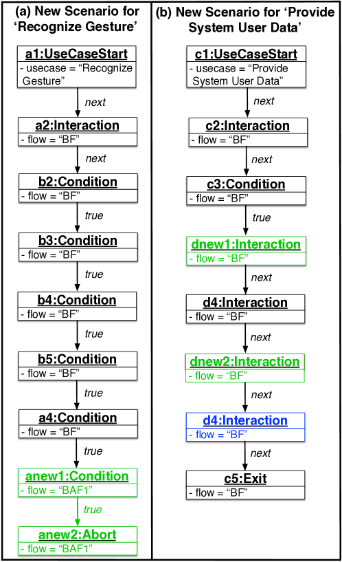
In Fig. 12, the algorithm follows a depth-first traversal of sm by following use case steps in sm that have corresponding steps in . To this end, when traversing condition steps, the algorithm follows alternative flows taken in (Lines 8-11). Whenever a Condition instance is encountered, the algorithm checks if the Condition instance exists also in (Line 8). If so, the algorithm proceeds with the condition branch taken in , i.e., the step following the Condition instance in (Line 11); otherwise, it takes the condition branch(es) which have not yet been taken in (Lines 12-30).
Alternative flows may lead to execution loops; this happens when alternative flows resume the execution of steps belonging to the originating flows. In our current implementation we generate scenarios that cover each loop body once. To this end, when processing condition steps, the algorithm checks if the branches that may lead to cycles have already been traversed (i.e., Lines 14 and 22). If it is the case, the traversal of the scenario is directed towards the branch that brings the scenario out of the cycles (i.e, the true branch for specific alternative flows and the false branch for bounded or global alternative flows as shown in Lines 15 and 23, respectively).
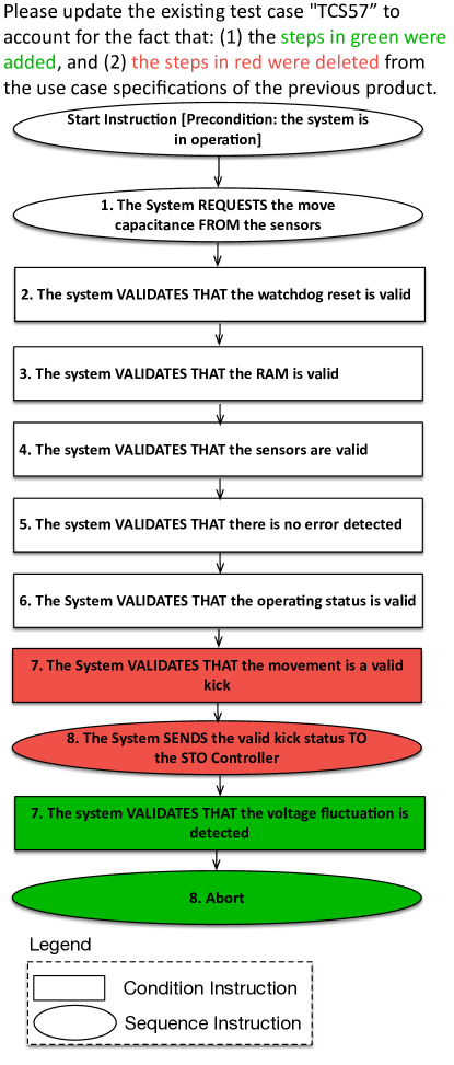
The algorithm in Fig. 12 always terminates since (1) the same alternative flow is covered only once and (2) the recursive traversal of the scenario model stops when an Exit or Abort step is reached (Line 32). The only exception is that of Exit steps of included use cases, which lead to the step that follows the Include step (Line 33). This Exit step belongs to the use case containing the Include step; therefore, the traversal will eventually reach an Exit or Abort step terminating the recursion. Before stopping the recursive traversal, the algorithm automatically compares and , and determines their differences to generate guidance for new test cases ( in Line 37). We provide a set of suggestions for adding, removing and updating test case steps corresponding to added, removed and updated use case steps in and . Finally, the algorithm adds , and to the result tuple (Line 38).
Fig. 13 gives two new scenarios derived from the scenarios in Fig. 9. Fig. 13(a) is derived from Fig. 9(a) and (b); Fig. 13(b) is derived from Fig. 9(c). The new scenario in Fig. 13(a) executes the new selected optional bounded alternative flow in which the use case Recognize Gesture aborts due to the voltage fluctuation (see Lines 8-12 in Table 1). While traversing sm for in Fig. 9(a), the new Condition instance anew1 and the new Abort instance anew2 (green-colored in Fig. 13(a)) are added in to execute the bounded alternative flow. in Fig. 13(b) executes the basic flow of the use case Provide System User Data of the new product where the order of one step is updated (blue-colored in Fig. 13(b)) and some new steps are introduced (green-colored) while some others are removed.
Fig. 14 shows the generated guideline to modify the test case verifying the retestable scenario in Fig. 9(a) for the new scenario in Fig. 13(a). The red and green colors, with a legend, on the scenario explains impacted parts of the corresponding test case. The red steps are deleted while the green ones are added to the scenario. Using this information, the engineer adds and deletes test case steps to cover the new scenario.
Fig. 15 shows the header of the test case verifying the new scenario in Fig. 13(a) with the description of the functions under test. For simplification, we omit the implementations of the executable test case. We use the guidance to derive the new test case from the test case in Fig. 16 verifying the scenario in Fig. 9(a). The bold lines in Fig. 15 are the new objectives and methods of the test case that correspond to the new use case steps in Fig. 13(a) (i.e., anew1 and anew2).
A new scenario might be derived separately from multiple old scenarios. After all the new scenarios are identified for the new product, we automatically detect such new scenarios and provide guidance for only the test cases of the old scenarios from which the engineer generates the new test cases with the least possible changes (Line 19 in Fig. 6). We rank those old scenarios according to the number of changes. If the number of changes are the same, we give priority to scenarios with more changes removing test case steps. We assume that removing test case steps is more convenient than adding new steps. For instance, the new scenario in Fig. 13(a) is derived from two scenarios in Fig. 9(a) and (b). To generate a test case verifying the new scenario in Fig. 13(a), the engineer can modify one of the test cases verifying the scenarios in Fig. 9(a) and (b). In Fig. 13(a), our approach provides guidance for both scenarios because the number of changes and the number of removed and added test case steps are the same for the two scenarios.
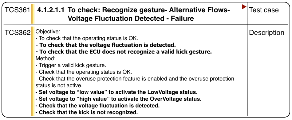
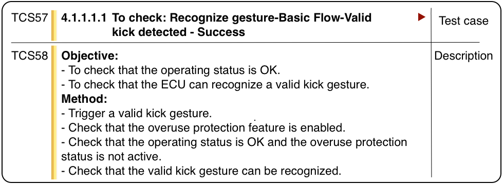
5.3 Step 4: Impact Report Generation
We automatically generate an impact report from the classified test cases of each previous product in a product line (Step 4 in Fig. 4). To enable engineers to select test cases from more than one test suite and thus maximize the number of test cases that can be inherited from previous products, we compare all the test suites in the product line. We then identify sets of new scenarios and reusable and retestable test cases for the product line. Assume that there are previous products in a product line. , , …, and are the sets of new scenarios we identify when we compare a new product with each previous product. To minimize the number of new test cases the engineer needs to generate, we compute the intersection of the sets of new scenarios ( = ). In other words, a scenario is considered as new only if has not been exercised in any of the previous products. Indeed, the scenarios which are not in the intersection of the sets are covered by at least one reusable or retestable test case in one of the previous products. If a scenario is exercised only by reusable test cases, we select the test case belonging to the most recent product, based on the date of creation of the product. Our rationale is that recent test case implementations are more likely to be reusable (e.g., they do not require updated setup instructions). We do the same when a scenario is exercised only by retestable test cases. Instead, if a scenario is exercised by both reusable and retestable test cases, we list the previous products in which the test case is identified as either retestable or reusable. Engineers then should decide from which previous product to take the test case.
Based on the system under test, engineers decide whether to select test cases from a single test suite or from multiple test suites in the product line. For example, if multiple products include different setup procedures (e.g., due to different hardware architecture or library versions being used) that need to be executed at the beginning of each test case, it is more practical to select test cases from a single test suite.
6 Prioritization of System Test Cases
Test case prioritization is implemented as a pipeline (see Fig. 17). The pipeline takes as input the test suite of the new product, the test execution history of the previous products (i.e., the outcome of each test case of the product test suite, for each previous product and version), the size of the use case scenarios exercised by the test cases, the classification of the test cases (i.e., reusable or retestable), and the PL use case. A new version of a product is deployed after the previous version has been tested and fixed. Requirements remain identical from version to version of the same product. When requirements evolve, they are considered to characterize a different, new product in the product line. Based on a prediction model using these factors, the test cases of the given test suite are sorted to maximize the likelihood of executing failing test cases first.
The prioritization pipeline gives the highest priority to test cases covering new scenarios (i.e., scenarios not available for previous products) since they exercise features that have never been tested before. The prioritization of retestable and reusable test cases is instead driven by a set of factors typically correlated with the triggering of failures, according to the relevant literature (e.g., Srikanth2005 ; Engstrom2011b ; Wong1997 ; Rothermel2001 ; Li2007 ): the number of previous products in which the test case failed, the number of previous products’ versions in which the test case failed, the size of the scenario exercised by the test case, the degree of variability in the use case scenario exercised by the test case, and the classification of the test case (i.e., reusable or retestable). Note that different versions of a product share the same test suite because functional requirements do not vary across the versions of the same product. Since this test suite does not contain obsolete test cases, they are not considered to build the regression model. The number of previous products in which the test case failed and the number of versions in which the test case failed capture the fault proneness of the test cases, a factor typically considered by other test case prioritization approaches Srikanth2005 ; Engstrom2011b . The size of the use case scenario exercised by a test case is measured in terms of the number of use case steps it contains. The scenario size captures the complexity of the operations performed by the system during the execution of the test case, under the assumption that longer scenarios require more complex software implementations. Implementation complexity is one of the factors considered in other requirements-based prioritization approaches Srikanth2005 . The degree of variability in the use case scenario exercised by a test case is measured by counting the number of decision elements included in the scenario. In the presence of high variability, it is more likely that some of the system properties verified by the test case are not implemented properly. Finally, the classification of a test case as retestable is considered for prioritization since, by definition, the scenario exercised by a retestable test case might be affected by changes in behaviour and thus may trigger a failure.
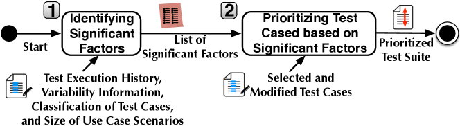
All these factors mentioned above may have varying importance for test case prioritization in different product lines due to technical and organizational factors. Some factors may even not significantly affect test case prioritization for some product lines. To account for the varying importance of risk factors, the pipeline identifies factors significantly correlated with the presence of failures. Test cases are then prioritized based on a prediction model relying on the correlated factors.
The prioritization pipeline includes two steps. In Step 1, Identifying significant factors, our approach automatically identifies significant factors for prioritizing the test cases of a new product. To this end, we employ logistic regression Hosmer2013 , i.e., a predictive analysis to determine the relationship between one dependent binary variable (i.e., the failure of a test case) and one or more independent variables, which might be either numeric (e.g., the number of the products in which the test case failed in the past) or binary (e.g., the fact that a test case has been classified as retestable).
| Product ID | Version ID | Test Case ID | Fails | Retestable (R) | Size of the Use Case Scenario (S) | Degree of Variability of the Scenario (V) | # of Previous Products in which it Fails (FP) | # of Previous Versions in which it Fails (FV) |
|---|---|---|---|---|---|---|---|---|
| P1 | V1 | TC1 | 1 | 0 | 8 | 2 | 0 | 0 |
| P1 | V1 | TC2 | 0 | 0 | 4 | 1 | 0 | 0 |
| P1 | V2 | TC1 | 1 | 0 | 8 | 2 | 0 | 1 |
| P1 | V2 | TC2 | 0 | 0 | 4 | 1 | 0 | 0 |
| P1 | V3 | TC1 | 0 | 0 | 8 | 2 | 0 | 2 |
| P1 | V3 | TC2 | 0 | 0 | 4 | 1 | 0 | 0 |
| P1 | V4 | TC1 | 0 | 0 | 8 | 2 | 0 | 2 |
| P1 | V4 | TC2 | 0 | 0 | 4 | 1 | 0 | 0 |
| P2 | V1 | TC1 | 1 | 1 | 9 | 3 | 1 | 2 |
| P2 | V1 | TC2 | 0 | 0 | 4 | 1 | 0 | 0 |
| P2 | V1 | TC3 | 0 | 0 | 4 | 1 | 0 | 0 |
| P2 | V2 | TC1 | 0 | 1 | 9 | 3 | 1 | 3 |
| P2 | V2 | TC2 | 1 | 0 | 4 | 1 | 0 | 0 |
| P2 | V2 | TC3 | 0 | 0 | 4 | 1 | 0 | 0 |
| P2 | V3 | TC1 | 0 | 1 | 9 | 3 | 1 | 3 |
| P2 | V3 | TC2 | 0 | 0 | 4 | 1 | 0 | 1 |
| P2 | V3 | TC3 | 0 | 0 | 4 | 1 | 0 | 0 |
| P3 | V1 | TC1 | 1 | 1 | 9 | 3 | 2 | 3 |
| P3 | V1 | TC2 | 1 | 1 | 5 | 2 | 1 | 1 |
| P3 | V1 | TC3 | 0 | 0 | 4 | 1 | 0 | 0 |
| P3 | V2 | TC1 | 1 | 1 | 9 | 3 | 2 | 4 |
| P3 | V2 | TC2 | 0 | 1 | 5 | 2 | 1 | 2 |
| P3 | V2 | TC3 | 0 | 0 | 4 | 1 | 0 | 0 |
In our context, the logistic regression model estimates the logarithm of the odds that a test case fails. The logistic regression model is trained using variability information, the size of the use case scenarios exercised by the test cases, the classification of the test cases, and the execution history of the test cases for previous products. The logistic regression model has the following form:
where is the probability that test case fails, is the degree of variability of the scenario exercised by the test case (i.e., the number of decision elements in the scenario), is the size of the use case scenario exercised by the test case (i.e., the number of steps), is the number of failing products, is the number of failing versions, and indicates whether the test case has been classified as retestable. is the intercept, while are coefficients which are derived, using the iteratively reweighted least squares approach Coleman-SSI-1980 , to estimate the effect size on the failure probability.
We rely on the R environment Rproject to derive the logistic regression model. Our toolset automatically generates from the available data the training data set to be processed by the R environment. Table 7 shows an excerpt of an example training data set generated by our toolset.
Table 7 includes the failure history of products , and to be used to prioritize the test cases for . Each row in Table 7 reports the information belonging to a single test case executed against a version of a product. The first and second columns represent the product and its version, respectively. The third column reports the test case identifier, while the fourth column indicates whether the test case fails (i.e., the dependent variable). The rest of the columns in Table 7 represent independent variables used to predict failure. The fifth column indicates if the test case has been classified as retestable. The sixth column reports the size of the use case scenario exercised by the test case. The seventh column reports the degree of variability of the scenario exercised by the test case. Table 7, for instance, shows that test case executed against covers nine use case steps while the same test case covers eight use case steps when executed against ; this is due to the covered use case scenario in including one additional variant element than the use case scenario covered in (see column Degree of Variability). Test case has been introduced in to cover one additional use case scenario not present in . The eighth and ninth columns report the number of products and the number of versions in which the test case fails, respectively.
To identify the significant factors for test case prioritization, we apply the p-value method of hypothesis testing based on Wald test Rice2007 . The method relies on the failure probability predicted by the regression model to determine whether there is evidence to reject the null hypothesis that there is no relationship between the two variables. The p-value indicates the likelihood of observing the data points when the null hypothesis is true. Therefore, if the p-value is smaller than a given threshold (we use 0.05) then it is unlikely that the dataset has been generated by chance and, consequently, the null hypothesis can be rejected (i.e., there is a relationship between the factor and the dependent variable). In the model, we keep the given factors whose p-value is smaller than the threshold. To automatically determine significant factors, we rely on the p-value computed by the Wald test on the logistic regression model trained by including all the factors. Finally, we derive a new, multivariate logistic regression model that includes only the significant factors. For example, the logistic regression model derived for one of the products used in our empirical evaluation (see P4 in Section 8) is the following:
This model, for example, does not include the number of failing products () since it is not significant according to the computed p-value.
The generated logistic regression model is a predictive model that returns, based on the significant factors, the probability that a test case fails. In Step 2, Prioritize test cases, we prioritize test cases by relying on the probability calculated by the regression model. The test cases are sorted in descending order of probability and presented to engineers.
7 Tool Support
We have implemented our test case selection and prioritization approach as an extension of PUMConf. For accessing the tool and some representative models, see: https://sites.google.com/site/pumconf/.
Fig. 18 shows the layered architecture of our tool PUMConf. It is composed of three layers: (i) the User Interface (UI) layer, (ii) the Application layer, and (iii) the Data layer. We briefly introduce each layer and explain the new components, i.e., the gray boxes in Fig. 18.
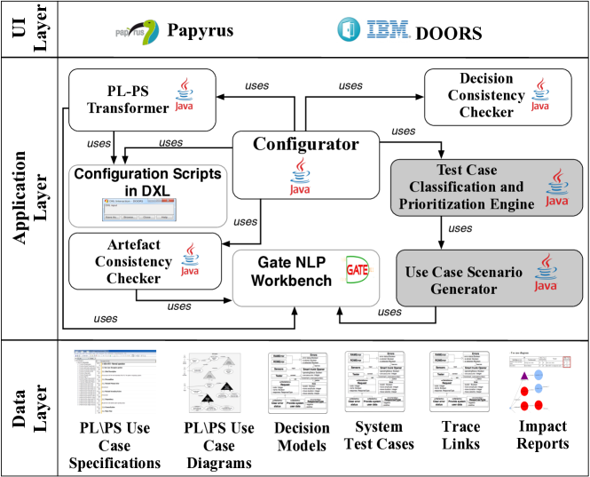
User Interface (UI) Layer supports creating and viewing PL and PS use case models (i.e., use case diagrams and specifications) and system test cases, and displaying the generated impact reports. We employ Papyrus (https://www.eclipse.org/papyrus/) for use case diagrams and IBM Doors (www.ibm.com/software/products/ca/en/ratidoor/) for use case specifications and system test cases. The impact reports are visualized as part of IBM Doors output using JGraph (https://www.jgraph.com/), Microsoft Excel (https://products.office.com/en/excel/) and html.
Application Layer supports, with the new components, the main activities of our approach in Fig. 3. The Configurator component coordinates the other components in the application layer. The Artifact Consistency Checker and Decision Consistency Checker components were introduced in our previous work Hajri2016c ; Hajri2018 . The Artifact Consistency Checker employs NLP to check the consistency of the PL use case diagram and the PL use case specifications complying with the RUCM template. To perform NLP, our tool employs the GATE workbench (http://gate.ac.uk/), an open source NLP framework. The Decision Consistency Checker supports inferring decision restrictions and checking their consistency. The PL-PS Transformer component annotates the use case specifications using NLP to automatically generate PS use case specifications. It uses scripts written in the Doors eXtension Language (DXL) to automatically (re)configure PS use case specifications.
We further implemented some new components: Test Case Classification and Prioritization Engine and Use Case Scenario Generator. The Use Case Scenario Generator also employs the GATE workbench to extract control flow information, i.e., the order of alternative flows and their conditions, from use case specifications. With the extracted control flow information, it identifies the new and already tested use case scenarios. These scenarios are used by the Test Case Classification and Prioritization Engine component to classify system test cases and to provide guidance to modify system test cases for new use case scenarios that have not been tested before. To prioritize system test cases, the Test Case Classification and Prioritization Engine employs R scripts (https://www.rdocumentation.org/) that implement logistic regression.
Data Layer. The PL and PS use case specifications are stored in the native IBM DOORS format while the PL and PS use case diagrams are stored as UML models. The decision models are saved in Ecore EclipseEMF . We generate the impact reports as Microsoft Excel spreadsheets and html pages. Depending on industrial practice, the traceability links between use case specifications and system test cases can be saved in Excel spreadsheets or in IBM DOORS link database.
8 Evaluation
Our objective is to assess, in an industrial context, whether our approach could improve test case reuse and reduce testing effort. This empirical evaluation aims to answer the following research questions (RQs):
-
•
RQ1. Does the proposed approach provide correct test case classification results? This research question aims to evaluate the precision and recall of the procedure adopted to classify the test cases developed for previous products.
-
•
RQ2. Does the proposed approach accurately identify new scenarios that are relevant for testing a new product? This research question aims to evaluate the precision and recall of the approach in identifying the new scenarios to be tested for a new product (i.e., new requirements not covered by existing test cases).
-
•
RQ3. Does the proposed approach successfully prioritize test cases? This research question aims to determine whether the approach is able to effectively prioritize system test cases that trigger failures and thus can help minimize testing effort while retaining maximum fault detection power.
-
•
RQ4. Can the proposed approach significantly reduce testing costs compared to current industrial practice? This research question aims to determine to what extent the proposed approach can help significantly reduce the cost of defining and executing system test cases.
8.1 Subject of the Study
The subject of our study is the Smart Trunk Opener (STO) system developed by our industry partner IEE. STO has been selected for the assessment of our approach since it is one of the newest IEE products involving multiple customers requiring varying features. The development history of the STO product line includes five products delivered to different car manufacturers. STO customers include major car manufacturers working in the European, Asian and US markets, with 2017 sales ranging from 200,000 to 3 million vehicles. For each product, IEE engineers developed multiple versions, each sharing the same functional requirements but differing with respect to non-functional requirements (e.g., hardware selection or performance optimizations). In total, STO includes 54 versions.
| # of Use Cases | # of Variation Points | # of Basic Flows | # of Altern. Flows | # of Steps | # of Optional Altern. Flows | # of Optional Steps | |
| Essential UCs | 15 | 5 | 15 | 70 | 269 | 5 | 14 |
| Variant UCs | 14 | 3 | 14 | 132 | 479 | 8 | 13 |
| Total | 29 | 8 | 29 | 202 | 748 | 13 | 27 |
To develop the STO system, IEE engineers elicited requirements as use cases from an initial customer. For each new customer, they cloned the current use cases and identified differences to produce new use cases. IEE provided their initial STO documentation, which contained a use case diagram, use case specifications, and supplementary requirements specifications describing nonfunctional requirements and domain concepts. The initial documentation was the output of their current clone-and-own reuse practice. That documentation contains variability information only in the form of some brief textual notes attached to the relevant use case specifications. To model the STO requirements according to our product line use case modeling method, PUM Hajri2015 ; Hajri2016c , we first examined the initial STO documentation. Since the initial documentation contains almost no structured variability information, we had to work together with two IEE engineers (one software development manager and one embedded software engineer) to build and iteratively refine our models. When we started to study the STO documentation, the STO project was in its initial phase and there was only one prototype implementation to discuss with some potential customers. One may argue that it is not always easy to identify variations in requirements when a new project starts. However, the IEE engineers stated that, most of the time in their domain of applications, requirements and their variability can be identified with the first customer.
After studying the initial STO documentation and meeting with the IEE engineers, we built the PL use case diagram and specifications for STO. Table 8 provides an overview of the STO product line. The data in Table 8 shows that the system implements 29 use cases, each one being fairly complex since the use cases in total include 202 alternative flows (i.e., alternative cases to be considered when implementing the use case). The STO product line is highly configurable, with 14 variant use cases, 8 variation points, 13 optional alternative flows and 27 optional steps. Except for the conflict relationship between use cases and the variant order group, we used all the PUM features in the STO PL use case diagram and specifications. STO has the size and characteristics of typical embedded product line systems managing automotive components.
When discussions start with a customer regarding a specific product, IEE engineers need to make decisions on variability aspects documented in PL use case models. At a later stage, when IEE had already developed various STO products for different car manufacturers, we used PUMConf, together with engineers, to configure the PS use case models for five STO products. Configuration decisions were made on the PL use case models using the guidance provided by PUMConf. IEE also provided the test suites of the products.
All the generated PS use case models were confirmed by the IEE engineers to be correct and complete. The PL use case models that we derived from the initial STO documentation were sufficient to make all the configuration decisions needed in PUMConf and to generate the correct and complete PS use case models for the five STO products.
Table 9 reports information about the STO products including the number of versions for each product. In Table 9, the products are sorted according to their delivery date, with P1 being the first product of the product line, and P5 being the last.
| Product ID | # of Versions | # of Use Case Elements | # of Test Cases | ||
| Use Cases | Use Case Flows | Use Case Steps | |||
| P1 | 22 | 28 | 236 | 689 | 110 |
| P2 | 8 | 25 | 169 | 568 | 86 |
| P3 | 10 | 28 | 234 | 685 | 96 |
| P4 | 5 | 26 | 212 | 618 | 83 |
| P5 | 9 | 28 | 238 | 695 | 113 |
The different STO products are characterized by different test suites of different sizes while the same test suite is shared by all the versions of the same product since their functional requirements do not vary. The test cases have been traced to the use case specifications by IEE engineers. Note that requirements traceability is a systematic practice at IEE since it is enforced by automotive functional safety standards such as ISO-26262 ISO26262 . Column # Test Cases in Table 9 shows, for every product, the number of test cases belonging to the functional test suite of the product.
All the faults considered in our evaluation are real faults previously identified by IEE during testing. Because of the confidentiality agreement we signed with our industry partner, we cannot share fault data.
8.2 Experiment Setup
Our approach for test case classification can be applied using single-product settings (i.e., to classify and prioritize test cases that belong to a previous product) and whole-line settings (i.e., to classify test cases of multiple previous products). To evaluate our approach for test case classification and to spot differences in terms of classification results with the two configurations (e.g., number of test cases that can be reused), we applied the approach using both settings. To evaluate test case prioritization, we prioritized test suites developed to test different STO products. We applied test case prioritization to the entire test suite since its execution is required by safety standards for every product being released.
8.3 Results
This section discusses the results of our case study, addressing in turn each of the research questions.
8.3.1 RQ1: Does the proposed approach provide correct test case classification results?
To answer RQ1, we, together with two IEE engineers, inspected the classification results produced by the approach. We chose these engineers for their complementary roles and extensive experience. One was an embedded software engineer of the STO team and the other was in charge of managing STO development. We evaluated the approach in terms of the average precision and recall we computed over the three different classes according to standard formulas Sokolova:2009:SAP . In our context, a true positive is a test case correctly classified according to the expected class (e.g., a reusable test case classified as reusable). A false positive is a test case incorrectly classified as being part of a given class (e.g., a retestable test case classified as reusable). A false negative is a test case that belongs to a given class but has not been classified as such (e.g., a reusable test case not classified as reusable).
| Classified Test Suite | Product to be Tested | # of Reusable | # of Retestable | # of Obsolete | Precision | Recall |
| P1 | P2 | 94 | 2 | 14 | 1.0 | 1.0 |
| P1 | P3 | 105 | 2 | 3 | 1.0 | 1.0 |
| P1 | P4 | 102 | 2 | 6 | 1.0 | 1.0 |
| P1 | P5 | 84 | 22 | 4 | 1.0 | 1.0 |
| P2 | P3 | 85 | 0 | 1 | 1.0 | 1.0 |
| P2 | P4 | 83 | 0 | 3 | 1.0 | 1.0 |
| P2 | P5 | 67 | 16 | 3 | 1.0 | 1.0 |
| P3 | P4 | 91 | 0 | 5 | 1.0 | 1.0 |
| P3 | P5 | 77 | 17 | 2 | 1.0 | 1.0 |
| P4 | P5 | 77 | 5 | 1 | 1.0 | 1.0 |
| Classified Test Suites | Product to be Tested | Reusable | Retestable | Obsolete | Precision | Recall |
|---|---|---|---|---|---|---|
| P1 | P2 | 94 | 2 | 14 | 1.0 | 1.0 |
| P1, P2 | P3 | 107 | 0 | 2 | 1.0 | 1.0 |
| P1, P2, P3 | P4 | 102 | 0 | 12 | 1.0 | 1.0 |
| P1, P2, P3, P4 | P5 | 93 | 15 | 1 | 1.0 | 1.0 |
Tables 10 and 11 provide the results for the single-product and whole-line settings, respectively. The first two columns report the ID of the product(s) whose test suite(s) have been considered for classification and the ID of the product being tested, respectively. The next three columns provide the number of test cases belonging to the three classes. The last two columns indicate precision and recall. We observe that the approach has perfect precision and recall. This is the result of meticulous requirements modeling and system testing practices in place at IEE where functional requirements are documented by means of use cases together with proper traceability to test cases. These practices enable a precise identification of impacted scenarios and consequently the correct classification of test cases. It is typical practice for companies developing embedded, safety-critical systems, since requirements need to be traced and tested to comply with international safety standards (e.g., ISO 26262 ISO26262 and DO178C DO178C ). At IEE, functional requirements are elicited in the form of use case specifications, and system test cases are manually derived from the use case specifications. IEE engineers manually analyze use case specifications and write system test cases for use case scenarios to be tested. In our case study, each system test case exercises a use case scenario described in the use case specifications. Therefore, our approach is perfectly accurate, i.e., perfect precision and recall for RQ1. In general, our approach is expected to work well in industrial contexts where there is traceability, at the appropriate level of granularity, between requirements and system test cases.
As we stated in Section 5.2.3, there are few cases (i.e., multiple scenarios taking the same alternative flows with different orders and more than one scenario taking the same bounded or global alternative flow) where finer-grained traceability links are needed to retrieve test cases. However, in our case study, we did not encounter the two cases we mentioned above, which are expected to be rare.
8.3.2 RQ2: Does the proposed approach accurately identify new scenarios that are relevant for testing a new product?
To answer RQ2, we checked if the new scenarios were exercised by the test cases in the manually implemented test suites of the new products. If so, we considered those new scenarios relevant. In addition, we, together with IEE engineers, checked whether the new scenarios that were not exercised were relevant for testing these new products. Based their domain knowledge, engineers described irrelevant scenarios as scenarios having various errors which are unlikely to happen at the same time during system execution (e.g., having temperature and voltage errors at the same time). These scenarios were not considered worth testing.
We classified the new scenarios as true positive (i.e., a scenario identified by our approach and relevant for testing), false positive (i.e., a scenario identified by our approach but not relevant for testing), and false negative (i.e., a scenario tested by IEE but not identified by our approach). We computed precision and recall accordingly.
| Classified | Product | New Scenarios Identified | New Scenarios | Precision | Recall | |||
| Test Suite | to be Tested | Relevant (TP) | Tested by Engineers | Not Tested | Not Relevant (FP) | Not Identified (FN) | ||
| P1 | P2 | 3 | 3 | 0 | 0 | 0 | 1.0 | 1.0 |
| P1 | P3 | 3 | 3 | 0 | 0 | 0 | 1.0 | 1.0 |
| P1 | P4 | 2 | 1 | 1 | 0 | 0 | 1.0 | 1.0 |
| P1 | P5 | 27 | 23 | 4 | 0 | 0 | 1.0 | 1.0 |
| P2 | P3 | 1 | 1 | 0 | 0 | 0 | 1.0 | 1.0 |
| P2 | P4 | 1 | 1 | 0 | 0 | 0 | 1.0 | 1.0 |
| P2 | P5 | 22 | 22 | 0 | 0 | 0 | 1.0 | 1.0 |
| P3 | P4 | 1 | 1 | 0 | 0 | 0 | 1.0 | 1.0 |
| P3 | P5 | 26 | 23 | 3 | 0 | 0 | 1.0 | 1.0 |
| P4 | P5 | 10 | 10 | 0 | 0 | 0 | 1.0 | 1.0 |
| Classified | Product | New Scenarios Identified | New Scenarios | Precision | Recall | |||
| Test Suites | to be Tested | Relevant (TP) | Tested by Engineers | Not Tested | Not Relevant (FP) | Not Identified (FN) | ||
| P1 | P2 | 3 | 3 | 0 | 0 | 0 | 1.0 | 1.0 |
| P1, P2 | P3 | 1 | 1 | 0 | 0 | 0 | 1.0 | 1.0 |
| P1, P2, P3 | P4 | 0 | 0 | 0 | 0 | 0 | 1.0 | 1.0 |
| P1, P2, P3, P4 | P5 | 14 | 9 | 5 | 0 | 0 | 1.0 | 1.0 |
Tables 12 and 13 report the results obtained using the single-product and whole-line settings, respectively. The third, fourth, and fifth columns provide the number of relevant scenarios identified by our approach, and, among these, the number of scenarios tested and not tested by IEE engineers. The sixth column (Not Relevant) indicates the number of irrelevant scenarios. The columns named New Scenarios Not Identified provide the number of scenarios tested by IEE engineers but not identified by our approach. The last two columns report precision and recall. All the new scenarios identified by our approach are relevant; they are covered by the test cases produced by IEE engineers. Consequently, the approach has perfect precision and recall.
In addition, we observe from Table 13 that the availability of additional products in the whole-line settings enables the identification of additional new scenarios, and consequently more accurate testing. This is what happens for product P5, in which the whole-line settings lead to the identification of 14 new scenarios. Five of these new scenarios have not been tested by engineers in any of the existing products. More precisely, the test suites of P1 and P3 enable the identification of four and three scenarios not tested in the test suite of P5, respectively; only two of these scenarios are tested by both for a total of five new scenarios identified. This difference between existing test suites is explained by the fact that certain test teams have defined more complete test suites (i.e., the test team for P1 and P3). Since new scenarios are identified based on existing test cases (see Section 5.2.4), for products with more complete test suites, the availability of more test cases may lead to the identification of additional new scenarios.
8.3.3 RQ3: Does the proposed approach successfully prioritize test cases?
To answer RQ3 in a realistic fashion, we applied our test case prioritization approach to sort test cases in the test suites of four STO products (i.e., P2, P3, P4 and P5). In total, we built four logistic regression models, one for each STO product. To evaluate the quality of the predictions, we relied on historical data. To maximize the realism of results, we prioritized the test cases that belonged to the test suites originally developed by IEE engineers and ignored the new test scenarios we had identified (Section 5). This did not introduce bias in the evaluation since test cases exercising new scenarios are always on top of the prioritized test suite and their execution is always necessary independently from their predicted likelihood to trigger failures. In the following, we discuss our results including the identification of significant factors and the effectiveness of prioritizing failing test cases for each product. Finally, we evaluate to what extent the availability of additional historical data positively affects test cases prioritization.
| Classified Test Suites | Product to be Tested | Significant Factors | Odds Ratio |
|---|---|---|---|
| P1 | P2 | V; S; FV | 0.35; 1.08; 2.09 |
| P1, P2 | P3 | V; S; FV | 0.35; 1.06; 1.85 |
| P1, P2, P3 | P4 | V; S; FV; R | 0.78; 1.04; 1.71; 0.36 |
| P1, P2, P3, P4 | P5 | V; S; FP; FV; R | 0.36; 1.04; 0.92; 1.87; 1.95 |
Legend: V=Degree of Variability, S=Size, FP=Failing Products, FV=Failing Versions, R=Retestable.
| Classified Test | Product to be | AUC Ratio | %Test Cases Executed to Cover | %Failing Test Cases Covered | |
|---|---|---|---|---|---|
| Suites | Tested | (Observed/Ideal) | All the Failing Test Cases | 80% of the Failing Test Cases | with 50% of the Test Cases |
| P1 | P2 | 0.98 (65.46/66.48) | 72.09% | 38.37% | 97.43% |
| P1, P2 | P3 | 0.99 (82/82.48) | 41.66% | 22.91% | 100% |
| P1, P2, P3 | P4 | 0.97 (71.02/72.97) | 51.80% | 22.89% | 95% |
| P1, P2, P3, P4 | P5 | 0.95 (101.32/105.97) | 26.54% | 18.58% | 100% |
Table 14 provides detailed information about the statistically significant factors identified by our approach based on logistic regression results (see Section 6).
Column Significant factors lists the significant factors identified for each product. In our analysis, we emulate past development by following the chronology of the products, in order to obtain realistic results that would have been obtained in practice. As expected, when more historical information is available, more factors tend to significantly correlate with observed failures. For example, we observe that the classification of a test case as retestable becomes significant after three products are included in the development history of the product line. This can be explained by the fact that updated configuration decisions impact a limited number of scenarios (i.e., the number of retestable test cases is usually low) and thus, this factor only becomes significant when enough examples of retestable test cases have occurred in previous products. As expected, the number of failing products also becomes significant after a sufficient number of products in the product line.
Column Odds Ratio presents the odds ratio of each significant factor. The odds ratio captures the effect size of the factor on the outcome of the regression model (i.e., the probability of observing a failing test case). A value above one indicates that the factor positively contributes to the outcome; otherwise it negatively contributes to the outcome. Note, however, that a statistical interaction with another factor may affect the odds ratio. The results show that the number of failing versions is the factor that impacts most positively the probability of failure. It is highly likely that a test case that failed in the past will fail again, which is in line with previous research results. The odds ratio for the number of failing versions varies between 1.71 and 2.09. We observe that, as expected, the number of failing products statistically interacts with the number of failing versions. This has been determined by running logistic regression on each factor separately. Certain factors show a positive regression parameters when considered alone but become negative when interacting with other factors in the multivariate regression model. In this case, this is probably due to the two factors being correlated.
To evaluate the effectiveness of test case prioritization, we measured (1) the percentage of failing test cases in the first half of the prioritized test cases, which provides insights regarding the effectiveness of the approach with half of the test budget, (2) the percentage of test cases that must be executed to cover 80% of the failing test cases, which determines the cost of running most of the failing test cases, and (3) the percentage of test cases that must be executed to exercise all failing test cases, to indicate the cost of achieving optimal fault detection. Finally, we compared our approach with the ideal case that executes all the failing test cases first. Table 15 and Fig. 19 summarize our findings.
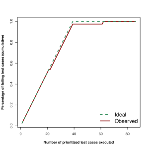
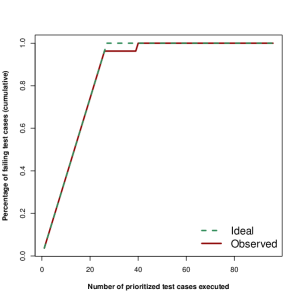
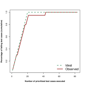
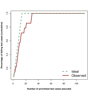
Table 15 shows that, for all the products in our evaluation, our approach covers more than 80% of the failing test cases by executing less than 50% of the test cases (see Columns %Failing test cases covered with 50% of the test cases and %Test cases executed to cover 80% of the failing test cases). We notice that the number of test cases required to cover all the failing test cases drops below 55% when the test execution history of at least two products becomes available (see Column %TCs executed to cover all the failing test cases). In the case of P5, for example, the execution of 27% of the test cases is sufficient to cover all the failing test cases. This is explained by the fact that newer products are more mature (i.e., they tend to fail less frequently) but is also due to logistic regression models improving over time. Indeed, for newer products, though there are fewer failing test cases, our approach remains accurate at giving higher priority to failing test cases. This capability is particularly relevant for industry since the early identification of failures enables early maintenance activities and, consequently, speeds up the product release.
To compare our approach with the ideal case, we computed the Area Under Curve (AUC) for the cumulative percentage of failing test cases in the executed test cases for both the ideal case and our prioritization approach, and computed the AUC ratio of the two. AUC is similar to Average Percentage of Faults Detected (APFD) do2006use , a standard measure to assess regression test prioritization. The difference is that our y-axis is the percentage of failing test cases, not the percentage of detected faults. Since each test case in our methodology exercises a distinct use case scenario, in a safety context, engineers told us this is more relevant than the number of faults as the number of failing test cases captures more accurately the level of risk. Fig. 19 shows the two curves for all products after the initial one. As for APFD, the best result is achieved when the AUC ratio is equal to one (i.e., the AUC for the observed data matches the ideal AUC). The results show that the proposed approach achieves impressive results since the AUC ratio is always greater than or equal to 0.95.
Finally, we checked if the logistic regression models improve over time due to the increase in available historical data. To this end, we compare the identification of significant factors and the effectiveness of prioritizing failing test cases when having historical data for a different number of past products. We focused on the prioritization of the test suite for P5, as it is the last product with the most historical data available. We therefore inspected and compared the P5 results obtained with data from (1) P1, (2) P1+P2, (3) P1+P2+P3, and (4) P1+P2+P3+P4. We also compared these results for P5 with the results obtained for earlier products (i.e., Tables 14 and 15).
Table 16 shows the significant factors identified. Similarly to Table 14, the number of significant factors increases with the number of available product versions. Notably, the number of failing products becomes significant after a sufficient number of products is present in the product line. Different from Table 14, in Table 16 the classification of a test case as retestable is always significant, which is due to the fact that, in P5, updated configuration decisions impact a higher number of scenarios than in the other cases. The numbers of retestable test cases for the different configurations in Table 16 are 22, 20, 20, and 15, respectively. Concerning Odds Ratios, we see values that are close to the ones in Table 14. Further, similar to Table 14, the number of failing products statistically interacts with the number of failing versions. However, different from Table 14, the classification of a test case as retestable has always an odds ratio above 1. This is due to a larger and different set of retestable test cases selected for P5 when compared to P4 (because of obsolete test cases, the set of test cases selected to build the regression model varies, see Section 6); P4 is the other product in Table 14 for which the classification of a test case as retestable is significant.
Concerning the test case prioritization results, Table 17 shows that an increasing number of available product versions leads to better results, i.e., a higher number of failing test cases detected for the same subset of the test suite. More precisely, the percentage of test cases executed to cover all the failing test cases decreases from 43.15%, when only one product is available, to 26.54%, when all the four products are available. A similar trend can also be observed for the percentage of test cases executed to cover 80% of the failing test cases. All the failing test cases can be covered by executing half of the test suite.
Finally, in Fig. 20, we compared the results of the ideal case for P5 with the results achieved when relying on the different sets of product versions. Unsurprisingly, the curves obtained by relying on more products are closer to the ideal one, i.e., better results are achieved when an increasing number of products is available.
| Classified Test Suites | Product to be Tested | Significant Factors | Odds Ratio |
|---|---|---|---|
| P1 | P5 | V; S; FV; R | 0.47; 1.09; 1.97; 2.11 |
| P1, P2 | P5 | V; S; FV; R | 0.37; 1.06; 1.87; 1.78 |
| P1, P2, P3 | P5 | V; S; FP; FV; R | 0.38; 1.04; 0.83; 1.95; 2.08 |
| P1, P2, P3, P4 | P5 | V; S; FP; FV; R | 0.36; 1.04; 0.92; 1.87; 1.95 |
Legend: V=Degree of Variability, S=Size, FP=Failing Products, FV=Failing Versions, R=Retestable.
| Prioritized Test | Product to be | AUC Ratio | %Test Cases Executed to Cover | %Failing Test Cases Covered | |
|---|---|---|---|---|---|
| Suites | Tested | (Observed/Ideal) | All the Failing Test Cases | 80% of the Failing Test Cases | with 50% of the Test Cases |
| P1 | P5 | 0.89 (94.32/105.97) | 45.13% | 33.62% | 100% |
| P1, P2 | P5 | 0.91 (96.68/105.97) | 40.70% | 26.54% | 100% |
| P1, P2, P3 | P5 | 0.92 (98.46/106.46) | 33.62% | 25.66% | 100% |
| P1, P2, P3, P4 | P5 | 0.95 (101.32/105.97) | 26.54% | 18.58% | 100% |
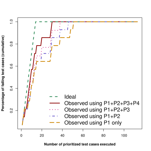
8.3.4 RQ4: Can the proposed approach significantly reduce testing costs compared to current industrial practice?
| Product to be tested | Test Cases To Be Implemented using the Proposed Approach | |
|---|---|---|
| Single-Product Settings | Whole-Line Settings | |
| P2 | 3/99 (3%) | 3/99 (3%) |
| P3 | 1/86 (1%) | 1/108 (1%) |
| P4 | 1/92 (1%) | 0/102 (0%) |
| P5 | 10/92 (11%) | 14/122 (11%) |
| Product | Test Suite | Number of | Test cases to be Executed to Cover all the Failing Test Cases | |
| to be tested | Size | Failing Test Cases | Current Practice | Proposed Approach |
| P2 | 86 | 39 | 84 (97.67%) | 62 (72.09%) |
| P3 | 96 | 27 | 80 (83.33%) | 40 (41.66%) |
| P4 | 83 | 20 | 77 (92.77%) | 43 (51.80%) |
| P5 | 113 | 14 | 69 (61.06%) | 30 (26.54%) |
Our test case classification and prioritization approach may reduce both (i) test case development costs (i.e., the number of test cases that need to be designed and implemented by engineers to test the software) and (ii) software development time (e.g., by executing more failing test cases at early stages of testing).
As a surrogate metric to measure the savings, for each product of the STO product line, we report the number and percentage of test cases that can be reused when adopting the proposed approach (see Table 18). Columns Single-Product Settings and Whole-Line Settings report the results achieved by the approach when reusing only the test cases inherited from one previous product and from the test suites of all the previous products in the product line, respectively. As seen in these two columns, the effort required to implement test cases is very limited since, with the proposed approach, engineers need to implement only the test cases required to cover new scenarios. For instance, in the whole-line settings for product P4, engineers do not need to implement any test case at all. Instead, testing teams at IEE currently do not rely on approaches that support systematic reuse of test cases, a practice which often leads to re-implementing most of the test cases from scratch. Finally, one benefit provided by the whole-line settings is the identification of new scenarios, as discussed in Section 8.3.2; this is the case of product P5 where the whole-line configuration settings lead to the identification of four additional scenarios not identified with the single-product settings.
To evaluate the impact of our approach on software development time, we measured the percentage of test cases that need to be executed in order to cover all the failing test cases in a product. Column Current Practice in Table 19 reports the percentage of test cases that need to be executed when considering the order followed by IEE engineers, which is based on domain knowledge. Column Proposed Approach reports the results we obtained. For all the products, our approach covers all the failing test cases with less test cases than the current practice. This is particularly true for product P5 where our approach requires the execution of less than half of the test cases prioritized by engineers. By using our approach, IEE can detect and fix failures earlier and thus speed up their software development.
We evaluated the run-time performance of our approach with the whole-line settings. We executed the test case classification and prioritization five times for each new product. The execution times are shown in Tables 20 and 21. Our tool was executed on an Intel quad-core i7 processor (2.40 GHz) with 6 MB Intel Smart Cache, and 8 GB of memory, running Windows 7.
| Classified Test Suites | Product to be Tested | 1st Run | 2nd Run | 3rd Run | 4th Run | 5th Run | Average |
|---|---|---|---|---|---|---|---|
| P1 | P2 | 21 | 16 | 13 | 12 | 13 | 15 |
| P1, P2 | P3 | 22 | 18 | 17 | 17 | 18 | 18.4 |
| P1, P2, P3 | P4 | 27 | 16 | 17 | 16 | 17 | 18.6 |
| P1, P2, P3, P4 | P5 | 29 | 16 | 17 | 17 | 16 | 19 |
| Prioritized Test Suites | Product to be Tested | 1st Run | 2nd Run | 3rd Run | 4th Run | 5th Run | Average |
|---|---|---|---|---|---|---|---|
| P1 | P2 | 15 | 13 | 15 | 13 | 12 | 13.6 |
| P1, P2 | P3 | 27 | 21 | 22 | 21 | 21 | 22.4 |
| P1, P2, P3 | P4 | 38 | 30 | 33 | 32 | 31 | 32.8 |
| P1, P2, P3, P4 | P5 | 49 | 40 | 41 | 39 | 38 | 41.4 |
According to the results, our approach requires less than 30 seconds to classify test cases in our case study, and less than 50 seconds to prioritize the same test cases. These results suggest that our selection and prioritization strategies are fast enough to be used in practical settings.
8.4 Reflections on Industrial Adoption
In addition to the research questions discussed above, we further reflect on the challenges for our approach to be widely transferable to industry. Based on our observations in the course of our efforts to get it adopted within IEE, we identified three challenges: modeling effort, degree of automation, and tool integration.
8.4.1 Modeling Effort
In the current practice at IEE, like in many other environments, there is no systematic way to model variability information in use case specifications and diagrams. IEE engineers attach brief notes to use case specifications to indicate what may vary in the specification. They are reluctant to use feature models traced to use case specifications because having feature models requires considerable additional modeling effort with manual assignment of traceability links at a very low level of granularity, e.g., sequences of use case steps. Therefore, in our approach, we employ the PL use case extensions presented in Section 2.1 that enable engineers to model variability directly in use cases without any feature modeling. In our discussions with IEE engineers, they stated that the effort required to apply the extensions for modeling variability was reasonable. They considered the extensions to be sufficiently simple to enable communication between engineers and customers.
IEE engineers discuss variability with the customer to decide what to include in each product. In order to employ our test case classification and prioritisation approach in such an industrial setting, each customer should also be trained about the modeling method. IEE engineers mentioned that training customers about the modeling method may be more of a challenge since the company may need customers’ consent and effort in modeling variability the way we suggest.
8.4.2 Degree of Automation
Based on our observations at IEE, we noticed that: (i) the current practice has no systematic way and automated tool support to decide which test cases from the previous products to execute and in which order for a new product; (ii) typically, multiple engineers from both the customer and supplier sides are involved in the decision-making process; (iii) engineers have to spend several days to manually review the entire set of system test cases from the previous products; and (iv) the intended updates of system test cases to cover new scenarios are manually identified and carried out by engineers. On the other hand, PUMConf supports test case classification and prioritisation activities in the context of product lines. The decision making process is automated in the sense that engineers are guided through the configuration decisions for classifying, prioritizing and modifying system test cases. Using PUMConf, for a new product, engineers select reusable and retestable system test cases to be run in the proposed order.
At this current stage, our approach does not support the evolution of PL use case models. We still need to address and manage changes in variability aspects of PL use case specifications and diagrams, such as adding a new variation point in the PL use case diagram. Engineers need to be automatically guided to classify and prioritize system test cases for such changes. As future work, we plan to provide an automated regression test selection approach addressing changes in PL use cases. Our approach currently supports only one objective for test case prioritization, i.e., prioritizing test cases with higher failure likelihood. But multiple objectives may be required such as minimum execution time and maximum severity fault identification. Therefore, we also plan to extend our automated test case prioritization approach with multi-objective search.
8.4.3 Tool Integration
PUMConf is currently implemented as a plugin in IBM DOORS, in combination with commercial modeling tools used at IEE, i.e., IBM Rhapsody and Papyrus. PUMConf highly depends on the outputs of these tools. In another company, these tools might be replaced with other tools or the newer versions of the same tools. Future changes in the tool chain from one company to another will need to fulfill the following constraints: (i) a new requirements management tool for PL use cases should be extensible in such a way that we can implement the PL use case extensions, (ii) a new tool for establishing traceability links should be extensible in such a way that we can assign traceability links conforming to our traceability metamodel, and (iii) a new tool for system test cases should be extensible in such a way that our approach takes inputs from the other tools to classify and prioritize system test cases.
8.5 Threats to Validity
Internal validity. To limit threats to internal validity, we considered the test cases developed by IEE engineers and the historical information collected over the years of system development. To avoid bias in the results, we considered the use case specifications written by IEE engineers and simply reformulated them according to the PUM methodology Hajri2015 ; Hajri2016c .
We used all the PUM features in the PL use case diagram and specifications for STO, with the exception of the conflict relationship between use cases and the variant order group. These two features are not needed in STO, and they do not lead to worse results as long as the input PL use case models are correct and complete. Indeed, the effect that a conflict relationship has on the writing of use case specifications is that, when a conflicting use case is selected for a variation point, then another use case (i.e., the conflicting one) should be excluded from the use case specifications. This results in the removal of use case scenarios and the addition of new, untested use case scenarios. Concerning the classification of system test cases, based on the validation of our algorithm, conflict relationships should not introduce errors in our results, once again as long as the input models are correct and complete. Concerning test case prioritization, since the products considered in our evaluation differ with respect to previous products in terms of both removal and addition of scenarios, we do not expect deviations from our findings, even in the presence of conflict relations in PL models. Similar conclusions can be drawn for the case of variant order groups. All our use case models were confirmed by the IEE engineers to be correct and complete.
External validity. To mitigate the threat to generalizability, we considered a software product line that includes nontrivial use cases, with multiple customers and many sources of variability, in an application domain where product lines are the norm. The fact that STO has been installed on cars developed by major car manufacturers all over the world guarantees that the configuration decisions for STO cover a wide spectrum of possible configurations.
In our experiments, we relied on test suites that exhaustively exercise the requirements for previous product versions. The testing process put in place by IEE aims to verify every use case scenario. It therefore ensures that the software under test conforms with its use case specifications and thus adheres to expected quality standards, which is mandatory for safety-critical systems. For this reason, we believe the IEE test suites to be representative of what is typically found in other types of safety-critical systems.
To achieve widespread applicability, we decided to rely on common requirements engineering practices (i.e., use case modeling and requirements traceability). Therefore, companies which already employ use cases for requirements elicitation only need to employ our extensions for product lines and restricted use case modeling. Based on our experience with various companies, we expect this transition to entail reasonable effort in safety-critical domains where these common practices are already in place to ensure compliance with standards. However, for organizations having less systematic and meticulous requirements and traceability practices, we expect more effort to be required for adoption as this represents a fundamental change in practices and skills.
9 Conclusion
This paper presents an automated test case classification and prioritization approach that supports use case-driven testing in product lines. For new products in a product line, it automatically classifies and prioritizes system test cases of previous product(s), and provides guidance in modifying existing system test cases to cover new use case scenarios that have not been tested in the product line before.
We improve the testing process in product lines by informing engineers about the impact of requirements changes on system test cases in a product family and by automatically and incrementally classifying and prioritizing system test cases. Such classification attempts to determine what test cases need to be rerun or modified, whereas prioritization helps ensure failing test cases are executed as soon as possible.
Our test case classification and prioritization approach is built on top of our previous work (i.e., Product line Use case Modeling method and the Product line Use case Model Configurator), and supported by a tool integrated into IBM DOORS. The key characteristics of our tool support are (1) the automated identification of the impact of requirements changes on existing system test cases, possibly leading to their selection or modification for a new product, (2) the automated identification of new use case scenarios in the new product that have not been tested in the product line, (3) the automated generation of guidance for modifying existing system test cases to cover those new scenarios, and (4) the automated prioritization of the selected system test cases for the new product. We performed an industrial case study in the automotive domain, whose results suggest that our approach is practical and beneficial in industrial settings. More specifically, it provides an effective way to classify and prioritize system test cases in industrial product lines and to provide guidance for modifying existing system test cases for new products.
Acknowledgments
We gratefully acknowledge funding from FNR and IEE S.A. Luxembourg, the grants FNR/P10/03 and FNR10045046, the Canada Research Chair program, and the European Research Council (ERC) under the European Union’s Horizon 2020 research and innovation programme (grant agreement No 694277).
References
- (1) Eclipse EMF, https://eclipse.org/modeling/emf/ (2018)
- (2) IEE (International Electronics & Engineering) S.A., http://www.iee.lu/ (2018)
- (3) The R project, https://www.r-project.org (2018)
- (4) Al-Hajjaji, M., Kruger, J., Schulze, S., Leich, T., Saake, G.: Efficient product-line testing using cluster-based product prioritization. In: AST’17, pp. 16–22 (2017)
- (5) Al-Hajjaji, M., Lity, S., Lachmann, R., Thum, T., Schaefer, I., Saake, G.: Delta-oriented product prioritization for similarity-based product-line testing. In: VACE’17, pp. 34–40 (2017)
- (6) Al-Hajjaji, M., Thum, T., Lochau, M., Meinicke, J., Saake, G.: Effective product-line testing using similarity-based product prioritization. Software and System Modeling (2016)
- (7) Al-Hajjaji, M., Thum, T., Meinicke, J., Lochau, M., Saake, G.: Similarity-based prioritization in software product-line testing. In: SPLC’14, pp. 197–206 (2014)
- (8) Arafeen, M.J., Do, H.: Test case prioritization using requirements-based clustering. In: ICST’13, pp. 312–321 (2013)
- (9) Arrieta, A., Sagardui, G., Etxeberria, L., Zander, J.: Automatic generation of test system instances for configurable cyber-physical sytems. Software Quality Journal 25(3), 1041–1083 (2017)
- (10) Arrieta, A., Wang, S., Sagardui, G., Etxeberria, L.: Test case prioritization of configurable cyber-physical systems with weight-based search algorithms. In: GECCO’16, pp. 1053–1060 (2016)
- (11) Arrieta, A., Wang, S., Sagardui, G., Etxeberria, L.: Search-based test case prioritization for simulation-based testing of cyber-physical system product lines. Journal of Systems and Software 149, 1–34 (2019)
- (12) Baller, H., Lity, S., Lochau, M., Schaefer, I.: Multi-objective test suite optimization for incremental product family testing. In: ICST’14, pp. 303–312 (2014)
- (13) Bertolino, A., Gnesi, S.: PLUTO: a test methodology for product families. In: PFE’03, pp. 181–197 (2003)
- (14) Binkley, D.: Semantics guided regression test cost reduction. IEEE Transactions on Software Engineering 23(8), 498–516 (1997)
- (15) Briand, L.C., Labiche, Y., He, S.: Automating regression test selection based on uml designs. Information and Software Technology 51, 16–30 (2009)
- (16) Bühne, S., Halmans, G., Pohl, K.: Modeling dependencies between variation points in use case diagrams. In: REFSQ’03, pp. 59–69 (2003)
- (17) Cabral, I., Cohen, M.B., Rothermel, G.: Improving the testing and testability of software product lines. In: SPLC’10, pp. 241–255 (2010)
- (18) do Carmo Machado, I., Mcgregor, J.D., Cavalcanti, Y.C., De Almeida, E.S.: On strategies for testing software product lines: A systematic literature review. Information and Software Technology 56(10), 1183–1199 (2014)
- (19) Chen, Y., Probert, R.L., Sims, D.P.: Specification-based regression test selection with risk analysis. In: CASCON’02 (2002)
- (20) Clarke, D., Helvensteijn, M., Schaefer, I.: Abstract delta modeling. In: GPCE’10, pp. 13–22 (2010)
- (21) Coleman, D., Holland, P., Kaden, N., Klema, V., Peters, S.C.: A system of subroutines for iteratively reweighted least squares computations. ACM Transactions on Mathematical Software 6(3), 327–336 (1980)
- (22) Devroey, X., Perrouin, G., Cordy, M., Samih, H., Legay, A., Schobbens, P.Y., Heymans, P.: Statistical prioritization for software product line testing: An experience report. Software and Systems Modeling 16(1), 153–171 (2017)
- (23) Devroey, X., Perrouin, G., Cordy, M., Schobbens, P.Y., Legay, A., Heymans, P.: Towards statistical prioritization for software product lines testing. In: VaMoS’14, pp. 1–7 (2014)
- (24) Do, H.: Recent advances in regression testing techniques. In: Advances in Computers, vol. 103 (2016)
- (25) Do, H., Rothermel, G.: On the use of mutation faults in empirical assessments of test case prioritization techniques. IEEE Transactions on Software Engineering 32(9), 733–752 (2006)
- (26) Dukaczewski, M., Schaefer, I., Lachmann, R., Lochau, M.: Requirements-based delta-oriented spl testing. In: PLEASE’13, pp. 49–52 (2013)
- (27) Engström, E.: Supporting decisions on regression test scoping in a software product line context - from evidence to practice. Ph.D. thesis, Lund University (2013)
- (28) Engström, E., Runeson, P.: Software product line testing - a systematic mapping study. Information and Software Technology 53, 2–13 (2011)
- (29) Engström, E., Runeson, P., Ljung, A.: Improving regression testing transparency and efficiency with history-based prioritization - an industrial case study. In: ICST’11, pp. 367–376 (2011)
- (30) Engström, E., Runeson, P., Skoglund, M.: A systematic review on regression test selection techniques. Information and Software Technology 52(1), 14–30 (2010)
- (31) Ensan, A., Bagheri, E., Asadi, M., Gasevic, D., Biletskiy, Y.: Goal-oriented test case selection and prioritization for product line feature models. In: ITNG’11, pp. 291–298 (2011)
- (32) Geppert, B., Li, J., Weiss, D.M.: Towards Generating Acceptance Tests for Product Lines, pp. 35–48. Springer (2004)
- (33) Gonzales-Sanchez, A., Piel, E., Abreu, R., Gross, H.G., van Gemund, A.J.: Prioritizing tests for software fault diagnosis. Software Practice and Experience 41(10), 1105–1129 (2011)
- (34) Haidry, S., Miller, T.: Using dependency structures for prioritization of functional test suites. IEEE Transactions on Software Engineering 39(2), 258–275 (2013)
- (35) Hajri, I., Goknil, A., Briand, L.C., Stephany, T.: Applying product line use case modeling in an industrial automotive embedded system: Lessons learned and a refined approach. In: MoDELS’15, pp. 338–347 (2015)
- (36) Hajri, I., Goknil, A., Briand, L.C., Stephany, T.: PUMConf: a tool to configure product specific use case and domain models in a product line. In: SIGSOFT FSE’16, pp. 1008–1012 (2016)
- (37) Hajri, I., Goknil, A., Briand, L.C., Stephany, T.: Incremental reconfiguration of product specific use case models for evolving configuration decisions. In: REFSQ’17, pp. 3–21 (2017)
- (38) Hajri, I., Goknil, A., Briand, L.C., Stephany, T.: Change impact analysis for evolving configuration decisions in product line use case models. Journal of Systems and Software 139, 211–237 (2018)
- (39) Hajri, I., Goknil, A., Briand, L.C., Stephany, T.: Configuring use case models in product families. Software and Systems Modeling 17(3), 939–971 (2018)
- (40) Hajri, I., Goknil, A., Stephany, T.: A change management approach in product lines for use case-driven development and testing. In: Poster Session - REFSQ’17 (2017)
- (41) Halmans, G., Pohl, K.: Communicating the variability of a software-product family to customers. Software and Systems Modeling 22(1), 15–36 (2003)
- (42) Harrold, M.J., Jones, J.A., Li, T., Liang, D.: Regression test selection for java software. In: OOPSLA’01 (2001)
- (43) Hemmati, H., Briand, L., Arcuri, A., Ali, S.: An enhanced test case selection approach for model-based testing: An industrial case study. In: FSE’10, pp. 267–276 (2010)
- (44) Hemmati, H., Fang, Z., Mantyla, M.V., Adams, B.: Prioritizing manual test cases in rapid release environments. Software Testing, Verification and Reliability 27(6) (2017)
- (45) Henard, C., Papadakis, M., Perrouin, G., Klein, J., Heymans, P., Traon, Y.L.: Bypassing the combinatorial explosion: Using similarity to generate and prioritize t-wise test configurations for software product lines. IEEE Transactions on Software Engineering 40(7), 650–670 (2014)
- (46) Henry, J., Henry, S.: Quantitative assessment of the software maintenance process and requirements volatility. In: CSC’93, pp. 346–351 (1993)
- (47) ISO: ISO-26262: Road vehicles – functional safety (2018)
- (48) Johansen, M.F., Haugen, Ø., Fleurey, F.: A survey of empirics of strategies for software product line testing. In: ICSTW’11, pp. 266–269. IEEE (2011)
- (49) Jr., D.W.H., Lemeshow, S., Sturdivant, R.X.: Applied Logistic Regression. Wiley (2013)
- (50) Kamsties, E., Pohl, K., Reis, S., Reuys, A.: Testing variabilities in use case models. In: PFE’03, pp. 6–18 (2004)
- (51) Khatibsyarbini, M., Isa, M.A., Jawawi, D.N., Tumeng, R.: Test case prioritization approaches in regression testing: A systematic literature review. Information and Software Technology 93, 74–93 (2018)
- (52) Knapp, A., Roggenbach, M., Schlingloff, B.H.: On the use of test cases in model-based software product line development. In: SPLC’14, pp. 247–251 (2014)
- (53) Korel, B., Koutsogiannakis, G., Tahat, L.H.: Application of system models in regression test suite prioritization. In: ICSM’08, pp. 247–256 (2008)
- (54) Krishnamoorthi, R., Mary, S.S.A.: Factor oriented requirement coverage based system test case prioritization of new and regression test cases. Information and Software Technology 51, 799–808 (2009)
- (55) Kundu, D., Sarma, M., Sarma, D., Mall, R.: System testing for object-oriented systems with test case prioritization. Software Testing, Verification and Reliability 19(4), 297–333 (2009)
- (56) Kung, D.C., Gao, J., Hsia, P.: Class firewall, test order, and regression testing of object-oriented programs. Journal of Object-Oriented Programming 8(2), 51–65 (1995)
- (57) Lachmann, R., Beddig, S., Lity, S., Schulze, S., Schaefer, I.: Risk-based integration testing of software product lines. In: VaMoS’17, pp. 52–59 (2017)
- (58) Lachmann, R., Lity, S., Al-Hajjaji, M., Furchtegott, F., Schaefer, I.: Fine-grained test case prioritization for integration testing of delta-oriented software product lines. In: FOSD’16 (2016)
- (59) Lachmann, R., Lity, S., Lischke, S., Beddig, S., Schulze, S., Schaefer, I.: Delta-oriented test case prioritization for integration testing of software product lines. In: SPLC’15, pp. 81–90 (2015)
- (60) Lachmann, R., Nieke, M., Seidl, C., Schaefer, I., Schulze, S.: System-level test case prioritization using machine learning. In: ICMLA’16, pp. 361–368 (2016)
- (61) Larman, C.: Applying UML and Patterns: An Introduction to Object-Oriented Analysis and Design and the Unified Process. Prentice Hall Professional (2002)
- (62) Lee, J., Kang, S., Lee, D.: A survey on software product line testing. In: SPLC’12, pp. 31–40 (2012)
- (63) Li, Z., Harman, M., Hierons, R.M.: Search algorithms for regression test prioritization. IEEE Transactions on Software Engineering 33(4), 225–237 (2007)
- (64) Lity, S., Al-Hajjaji, M., Thum, T., Schaefer, I.: Optimizing product orders using graph algorithms for improving incremental product-line analysis. In: VaMoS’17, pp. 60–67 (2017)
- (65) Lity, S., Lochau, M., Schaefer, I., Goltz, U.: Delta-oriented model-based spl regression testing. In: PLEASE’12, pp. 53–56 (2012)
- (66) Lity, S., Morbach, T., Thum, T., Schaefer, I.: Applying incremental model slicing to product-line regression testing. In: ICSR’16, pp. 3–19 (2016)
- (67) Lochau, M., Lity, S., Lachmann, R., Schaefer, I., Goltz, U.: Delta-oriented model-based integration testing of large-scale systems. Journal of Systems and Software 91, 63–84 (2014)
- (68) Mai, P.X., Goknil, A., Shar, L.K., Pastore, F., Briand, L.C., Shaame, S.: Modeling security and privacy requirements: a use case-driven approach. Information and Software Technology 100, 165–182 (2018)
- (69) Mai, P.X., Pastore, F., Goknil, A., Briand, L.C.: A natural language programming approach for requirements-based security testing. In: ISSRE’18, pp. 58–69 (2018)
- (70) Mai, P.X., Pastore, F., Goknil, A., Briand, L.C.: MCP: A security testing tool driven by requirements. In: ICSE’19, pp. 55–58 (2019)
- (71) Malaiya, Y.K., Denton, H.: Requirements volatility and defect density. In: ISSRE’99, pp. 285–298 (1999)
- (72) von Mayrhauser, A., Zhang, N.: Automated regression testing using dbt and sleuth. Journal of Software Maintenance 11(2), 93–116 (1999)
- (73) Mirarab, S., Ganjali, A., Tahvildari, L., Li, S., Liu, W., Morrissey, M.: A requirement-based software testing framework: An industrial practice. In: ICSM’08, pp. 452–455 (2008)
- (74) da Mota Silveira Neto, P.A., do Carmo Machado, I., McGregor, J.D., de Almeida, E.S., de Lemos Meira, S.R.: A systematic mapping study of software product line testing. Information and Software Technology 53, 407–423 (2011)
- (75) Muccini, H.: Using model differencing for architecture-level regression testing. In: SEAA’07 (2007)
- (76) Muccini, H., Dias, M., Richardson, D.J.: Software architecture-based regression testing. Journal of Systems and Software 79, 1379–1396 (2006)
- (77) Nardo, D.D., Alshahwan, N., Briand, L., Labiche, Y.: Coverage-based regression test case selection, minimization and prioritization: a case study on an industrial system. Software Testing, Verification and Reliability 25(4), 371–396 (2015)
- (78) Nebut, C., Fleurey, F., Traon, Y.L., Jezequel, J.M.: Automatic test generation: A use case driven approach. IEEE Transactions on Software Engineering 32(3), 140–155 (2006)
- (79) Nebut, C., Traon, Y.L., Jezequel, J.M.: System testing of product families: from requirements to test cases. In: Software Product Lines. Springer (2006)
- (80) Oster, S., Wübbeke, A., Engels, G., Schürr, A.: A survey of model-based software product lines testing. Model-Based Testing for Embedded Systems pp. 338–381 (2011)
- (81) Parejo, J.A., Sánchez, A.B., Segura, S., Ruiz-Cortés, A., Lopez-Herrejon, R.E., Egyed, A.: Multi-objective test case prioritization in highly configurable systems: A case study. Journal of Systems and Software 122(287–310) (2016)
- (82) Pohl, K., Bockle, G., van der Linden, F.: Software Product Line Engineering: Foundations, Principles, and Techniques. Springer (2005)
- (83) Qu, X., Acharya, M., Robinson, B.: Impact analysis of configuration changes for test case selection. In: ISSRE’11, pp. 140–149 (2011)
- (84) Ramesh, B., Jarke, M.: Toward reference models for requirements traceability. IEEE Transactions on Software Engineering 27(1), 58–93 (2001)
- (85) Reuys, A., Kamsties, E., Pohl, K., Reis, S.: Model-based system testing of software product families. In: CAiSE’05, pp. 519–534 (2005)
- (86) Reuys, A., Reis, S., Kamsties, E., Pohl, K.: The ScenTED method for testing software product lines. In: Software Product Lines, pp. 479–520 (2006)
- (87) Rice, J.A.: Mathematical Statistics and Data Analysis. Thomson Higher Education (2007)
- (88) Rothermel, G., Harrold, M.J.: Analyzing regression test selection techniques. IEEE Transactions on Software Engineering 22(8), 529–551 (1996)
- (89) Rothermel, G., Harrold, M.J.: A safe, efficient regression test selection technique. ACM Transactions on Software Engineering and Methodology 6(2), 173–210 (1997)
- (90) Rothermel, G., Harrold, M.J., Dedhia, J.: Regression test selection for C++ software. Software Testing, Verification and Reliability 10(2), 77–109 (2000)
- (91) Rothermel, G., Untch, R.H., Chu, C., Harrold, M.J.: Prioritizing test cases for regression testing. IEEE Transactions on Software Engineering 27(10), 929–948 (2001)
- (92) RTCA, EUROCAE: DO-178C: Software considerations in airborne systems and equipment certification (2018)
- (93) Runeson, P., Engström, E.: Regression testing in software product line engineering. In: Advances in Computers, vol. 86, pp. 223–263 (2012)
- (94) Schurr, A., Oster, S., Markert, F.: Model-driven software product lines testing: An integrated approach. In: SOFSEM’10, pp. 112–131 (2010)
- (95) Sokolova, M., Lapalme, G.: A systematic analysis of performance measures for classification tasks. Information Processing & Management 45(4), 427–437 (2009)
- (96) Srikanth, H., Banerjee, S.: Improving test efficiency through system test prioritization. Journal of Systems and Software 85, 1176–1187 (2012)
- (97) Srikanth, H., Hettiarachchi, C., Do, H.: Requirements based test prioritization using risk factors: An industrial study. Information and Software Technology 69, 71–83 (2016)
- (98) Srikanth, H., Williams, L., Osborne, J.: System test case prioritization of new and regression test cases. In: ESEM’05, pp. 64–73 (2005)
- (99) Srikanth, H., Williams, L., Osborne, J.: Towards the prioritization of system test cases. Software Testing, Verification and Reliability pp. 320–337 (2014)
- (100) Stricker, V., Metzger, A., Pohl, K.: Avoiding redundant testing in application engineering. In: SPLC’10, pp. 226–240 (2010)
- (101) Tahat, L., Korel, B., Harman, M., Ural, H.: Regression test suite prioritization using system models. Software Testing, Verification and Reliability 22(7), 481–506 (2012)
- (102) Tevanlinna, A., Taina, J., Kauppinen, R.: Product family testing: a survey. ACM SIGSOFT Software Engineering Notes 29(2), 12–12 (2004)
- (103) Tonella, P., Avesani, P., Susi, A.: Using the case-based ranking methodology for test case prioritization. In: ICSM’06, pp. 123–133 (2006)
- (104) Uzuncaova, E., Garcia, D., Khurshid, S., Batory, D.S.: Testing software product lines using incremental test generation. In: ISSRE’08, pp. 249–258 (2008)
- (105) Uzuncaova, E., Khurshid, S., Batory, D.S.: Incremental test generation for software product lines. IEEE Transactions on Software Engineering 36(3), 309–322 (2010)
- (106) Vaysburg, B., Tahat, L.H., Korel, B.: Dependence analysis in reduction of requirement based test suites. In: ISSTA’02, pp. 107–111 (2002)
- (107) Wang, C., Pastore, F., Goknil, A., Briand, L.C.: Automatic generation of acceptance test cases from use case specifications: an nlp-based approach. IEEE Transactions on Software Engineering (2020)
- (108) Wang, C., Pastore, F., Goknil, A., Briand, L.C., Iqbal, M.Z.Z.: Automatic generation of system test cases from use case specifications. In: ISSTA’15, pp. 385–396 (2015)
- (109) Wang, C., Pastore, F., Goknil, A., Briand, L.C., Iqbal, M.Z.Z.: UMTG: a toolset to automatically generate system test cases from use case specifications. In: ESEC/SIGSOFT FSE’15, pp. 942–945 (2015)
- (110) Wang, S., Ali, S., Gotlieb, A., Liaaen, M.: A systematic test case selection methodology for product lines: Results and insights from an industrial case study. Empirical Software Engineering 21(4), 1586–1622 (2016)
- (111) Wang, S., Ali, S., Gotlieb, A., Liaaen, M.: Automated product line test case selection: Industrial case study and controlled experiment. Software and Systems Modeling 16(2), 417–441 (2017)
- (112) Wang, S., Buchmann, D., Ali, S., Gotlieb, A., Pradhan, D., Liaaen, M.: Multi-objective test prioritization in software product line testing: An industrial case study. In: SPLC’14, pp. 32–41 (2014)
- (113) Wong, W.E., Horgan, J.R., London, S., Bellcore, H.A.: A study of effective regression testing in practice. In: ISSRE’97, pp. 230–238 (1997)
- (114) Yang, Q., Li, J.J., Weiss, D.M.: A survey of coverage-based testing tools. The Computer Journal 52(5), 589–597 (2009)
- (115) Yoo, S., Harman, M.: Regression testing minimization, selection and prioritization: a survey. Software Testing, Verification and Reliability 22(2), 67–120 (2012)
- (116) Yue, T., Briand, L.C., Labiche, Y.: Facilitating the transition from use case models to analysis models: Approach and experiments. ACM Transactions on Software Engineering and Methodology 22(1) (2013)
- (117) Zhang, M., Yue, T., Ali, S., Selic, B., Okariz, O., Norgre, R., Intxausti, K.: Specifying uncertainty in use case models. Journal of Systems and Software 144, 573–603 (2018)