Cryogenic Penning trap for precision measurements with (anti-)protons
Abstract
Cooling and detection schemes using laser cooling and methods of quantum logic can contribute to high precision CPT symmetry tests in the baryonic sector. This work introduces an experiment to sympathetically cool protons and antiprotons using the Coulomb interaction with a ion trapped in a nearby but separate potential well. We have designed and set up an apparatus to show such coupling between two identical ions for the first time in a Penning trap. In this paper, we present evidence for successful loading and Doppler cooling of clouds and single ions are presented. Our coupling scheme has applications in a range of high-precision measurements in Penning traps and has the potential to substantially improve motional control in these experiments.
Keywords: CPT symmetry, Penning traps, laser cooling, proton, antiproton
1 Introduction
Precise comparisons of the fundamental properties of matter/antimatter conjugates on the single particle level provide sensitive tests of CPT symmetry and the associated Lorentz symmetry in the Standard Model of Particle Physics [1, 2]. Important examples for this are comparisons of charge-to-mass ratios and magnetic moments of antiprotons and protons in Penning traps, where much experimental progress has been made recently [3, 4, 5, 6]. However, especially in case of the most precise magnetic moment measurements [5], which rely on the double Penning trap technique [7], the efforts are impeded by the absence of fast and deterministic preparation schemes for the motional state of the particle. Standard laser-based manipulation and cooling techniques well established in atomic physics cannot be applied directly to a single proton or antiproton, as the nuclear spin is their only internal degree of freedom. Therefore, current state of the art experiments apply sub-thermal resistive cooling methods, where the particle is coupled to cryogenic resistors [8]. These time-consuming procedures are ultimately required to prepare particles with motional temperatures at the level of K [9], which is essential for the high-fidelity spin state detection carried out in these experiments. In our currently most precise experiments, the sub-thermal cooling process constitutes the biggest time contribution in the measurement scheme. Therefore, such experiments would considerably profit from the development of laser-cooling schemes, which deterministically provide particles at mode-temperatures below the single-spin-state detection threshold within much reduced time. This is the inspiration and motivation to implement methods to sympathetically cool protons and antiprotons by coupling them to a co-trapped ‘logic’ ion that can be manipulated. Laser-cooling of the ‘logic’-ion and subsequent mode energy transfer will provide deterministically cold protons/antiprotons on time-scales of seconds. This will outperform the currently used methods due to considerably improved sampling statistics and the lower particle energies achieved, which will also further reduce systematic uncertainties. In future experiments, quantum logic inspired manipulation techniques could also be applied for state readout. Moreover, any techniques developed to mitigate this could well be extended to other charged particles that are difficult to manipulate directly, for example to highly charged ions for ultra-stringent tests of bound state quantum electrodynamics. Different coupling schemes have been proposed [10, 11] and are being worked on [12, 13, 14, 15, 16, 17]. This article describes the necessary steps to apply sympathetic cooling of protons and antiprotons via direct Coulomb coupling in an advanced Penning trap system. Towards this end, we demonstrate operation of a cryogenic Penning trap which supplies the laser cooled ions for sympathetic cooling and quantum logic spectroscopy.
2 Coupling concept
For charged particles, the Coulomb interaction provides the strongest coupling between particles and makes a natural choice for sympathetic cooling and state transfer. Proposals to exploit this idea for sympathetic cooling and state detection have been made using different approaches, namely trapping the particles in a common potential well [18], a shared-electrode-approach [10] and a free-space approach where the ions are located in separate potential wells [11]. As particles of opposite charge cannot be trapped in a common electrostatic potential well, we pursue the direct coupling approach in order to be able to address negatively charged particles as well. This approach has been successfully demonstrated in radio-frequency surface traps for particles of equal charge-to-mass ratio [12, 13].
In a Penning trap, charged particles are trapped by superimposing a strong magnetic field along the -direction with a static electric quadrupole field confining the motion along that axis. The resulting motion can be described by three modes: A harmonic oscillation with frequency along the -axis called the axial mode and two radial modes called magnetron and modified cyclotron modes with frequencies and [19].
For two charged particles with charges trapped in separate harmonic potential wells along the -axis with their equilibrium positions separated by and displacements from their respective equilibrium positions, the Coulomb interaction is described by the potential
| (1) |
where is the vacuum permittivity. Following the lines of [12] and using the standard ladder operators and , the first order interaction can be expressed as
| (2) |
where the last step assumes the angular frequencies and being close to each other. Here,
| (3) |
is the coupling rate, , denote the respective masses of the particles and is the reduced Planck constant. For resonant (identical) trap frequencies , the oscillators 1 and 2 swap energies with a period of , and exchange time .
For given particles, the coupling rate (3) scales strongly with the interparticle distance , and to a lesser extent with the axial trap frequencies . It would be favorable to combine low motional frequencies with a small distance between potential wells, but as decreasing the length scale of a two-well potential increases the gradient and curvature of the potential, the motional frequencies will scale unfavorably. Due to the different power law scaling of with and , a system with small length scales and a tighter confinement would be useful, but will ultimately demands for a miniaturised Penning trap that is currently under development. The version of the Penning trap which is installed for the first demonstration experiments presented in this manuscript is shown in Figure 1.
In order to achieve a stable coupling rate during the energy exchange periods (tens of milliseconds), axial frequency fluctuations should be small compared to the coupling rate (several or several tens of Hz).
The exchange times are fast compared to the expected ultra-low heating rates [8] in our cryogenic Penning trap system.
3 Experimental setup
The design of the experimental apparatus follows constraints defined by the apparatus of the BASE experiment, located at the antiproton decelerator of CERN [15]. This ensures mechanical compatibility of our system with the facilities at CERN to allow applying the demonstrated techniques on antiprotons in the future.
Superconducting magnet
The magnetic field for trapping ions is supplied by a high homogeneity wet superconducting magnet supplied by Oxford Instruments identical to the one described in [15], but operated at a higher magnetic field of . The experiment is placed in the horizontal room temperature bore. The magnet’s characterization results were in line with the data in [15] with a spatial homogeneity in a volume, less than over the trap stacks’ extent (about ) and a temporal stability of .
Cryo-mechanical setup
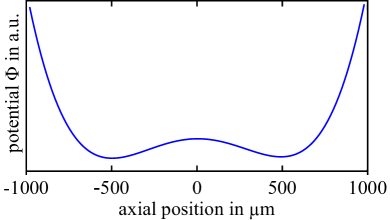
An overview of the vacuum system is shown in Figure 2. A horizontal bore magnet was chosen in order to be mechanically compatible with the BASE CERN setup.
The trap and wiring system form a separate cryogenic system independent from the temperature of the superconducting magnet.
This allows for maintenance and upgrades on the experiment while maintaining the carefully shimmed magnetic field.
All materials used in the magnet have an extremely low magnetic permeability to keep the field as homogeneous as possible.
The main cold stage is cooled by the second stage of a two-stage Gifford-McMahon cryocooler equipped with a helium gas heat exchanger for vibration isolation (ColdEdge Techologies SRDK-415 ULV UHV) between the cold head and experiment.
Our group measured an identical cooler to have vibration amplitudes below at the cold plate.
Homemade flexible braids made from oxygen free high conductivity copper (OFHC) further reduce vibrations transmitted to the cold temperature stages and allow for thermal contraction in the apparatus.
An aluminium radiation shield is thermally anchored to the first cooling stage of the cryocooler.
It is mechanically fixed to the magnet using a titanium structure and disc-shaped G10CR (a glass fiber filled epoxy for low temperature use) spacers with a maze structure to minimize heat leakage.
The calculated conductive heat load is about two percent of the cryocooler’s cooling power at , rendering it negligible.
The cryogenic trap system and wiring is mounted to the radiation shield using a similar structure.
To improve thermal contact, a vacuum annealed copper rod of purity is used for thermal contact between the cooler interface and the trap system.
Radiative heat transfer is suppressed using high-reflectivity aluminium foil and multi-layer insulation blankets.
Convective heat transfer is minimized by pumping the vacuum system to less than mbar with two turbomolecular pumps before cooling down.
With this system, we achieve temperatures of around near the trap.
Laser beam access is realized using custom in-vacuum mirrors to direct the beam through and out of the vacuum system.
All laser beam adjustment is done outside of the vacuum chamber on a dedicated platform.
Penning trap system
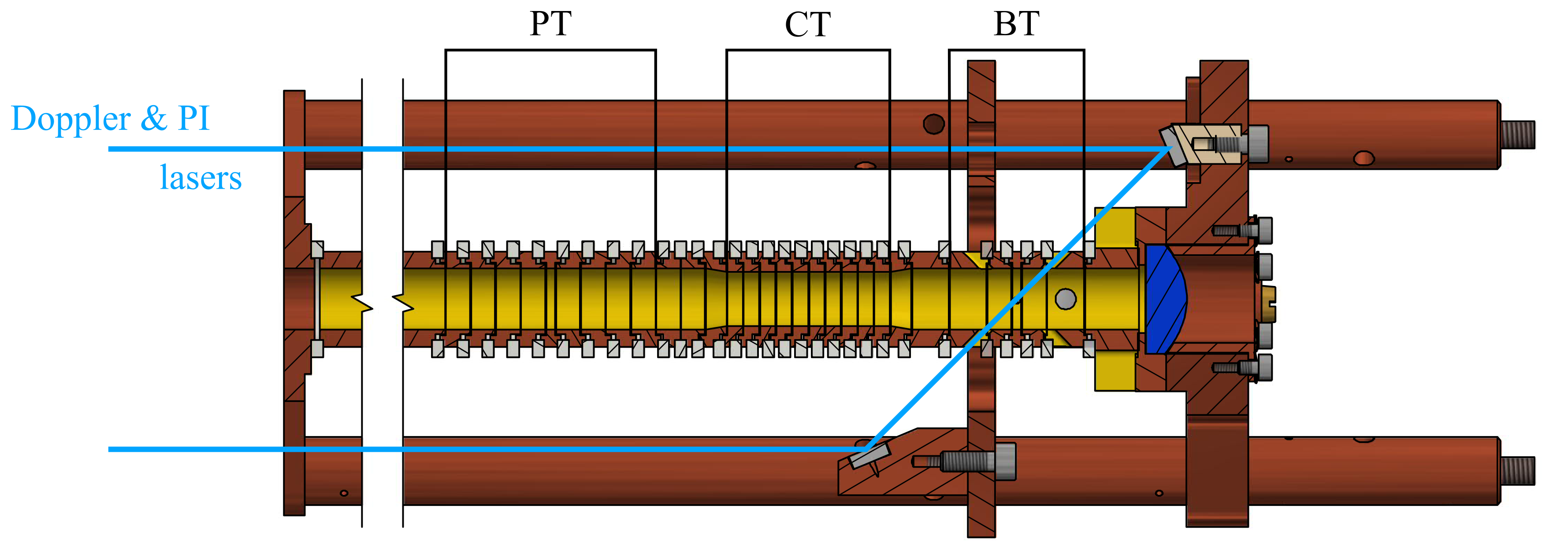
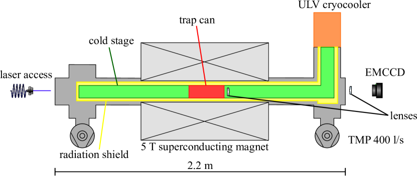
The current trap system (see Figure 3) consists of three cylindrical Penning traps with open endcaps located in a cylindrical OFHC ‘trap can’.
In order to reach the extreme high vacuum (XHV) regime necessary to prevent antiproton annihilation, the trap can can be hermetically sealed to form its own cryopumped vacuum system [20].
The trap stack is comprised of a ’beryllium trap’, a coupling trap and a precision trap.
Extra space for additional traps, such as a proton source trap, is currently reserved with a dummy electrode.
All trap electrodes are precision-machined from OFHC copper and gold-plated to prevent oxidation and minimize surface charge effects.
Electrodes are separated by sapphire rings that also ensure concentric alignment of the assembly.
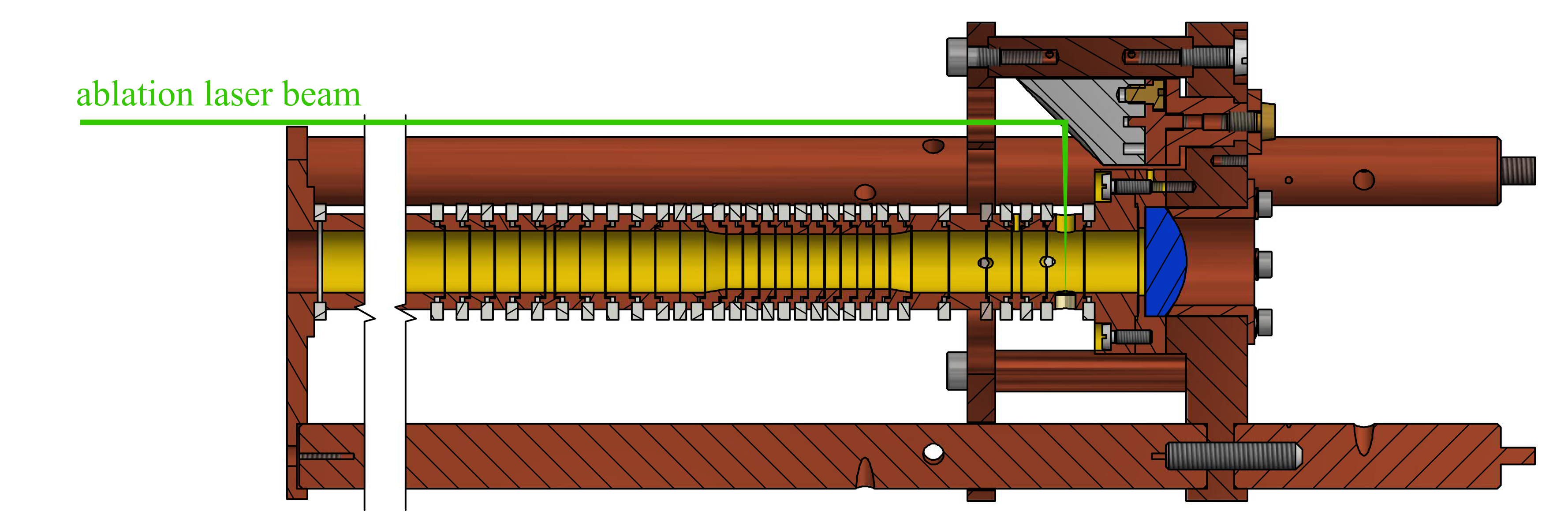
The beryllium trap (BT) is a compensated and orthogonal five-electrode Penning trap with laser access and loading capabilities.
Single pulses from a laser are tightly focused onto a solid beryllium target embedded in an endcap electrode using an in-vacuum off-axis parabolic (OAP) mirror to produce beryllium atoms and ions.
Laser beams for photoionization, cooling and repumping are introduced using custom in-vacuum mirrors and at an angle of with respect to the trap axis to allow coupling to all motional modes.
The laser beam is guided out of the vacuum chamber along a parallel path to facilitate adjustment of the beam and allow for beam position monitoring.
A custom-made aspheric lens (numerical aperture NA=0.25) collects fluorescence light, which is focused and directed onto either an EMCCD camera (Andor iXon 885) or a photomultiplier tube (Hamamatsu H8259-01) for state detection using a lens outside of the vacuum system.
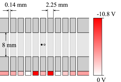
The coupling trap (CT) is a stack of ten equally sized electrodes that allows for applying a double-well potential suitable for coupling the axial motional modes of two ions.
For the first demonstration of the direct motional coupling of two beryllium ions in a double-well potential, we will use a trap geometry with an inner diameter of , an inter-ion distance of and , resulting in an exchange time and a coupling rate .
The precision trap (PT) is a compensated, orthogonal five-electrode trap [15] that can be used for high-precision radio-frequency spectroscopy of protons.
All endcap electrodes are segmented into multiple segments to allow for adiabatic transport between traps.
Traps are connected with transport electrodes and the segments between the coupling electrodes and the other traps are tapered.
Trap voltages are supplied by a homebuilt voltage source [21] and amplifiers (APEX PA98). They are connected to the electrodes using low-pass filters on all three temperature stages to reduce noise and ensure thermalization of the lines. The DC voltage source used is capable of a update rate and limited by low-pass filters with a total cut-off frequency of outside the vacuum chamber and on the cryogenic stages. Additional coaxial lines allow for axial excitation using an endcap electrode and radial excitation using a segmented correction electrode. The system is prepared to be upgraded with image current detection systems consisting of tank circuits and ultra-low noise amplifiers to enable resistive cooling and motional frequency measurements on protons [22].
Laser systems
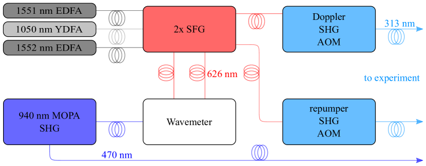
The laser setup is shown in figure 4.
It is comprised of an ablation laser for ablation of atoms and ions, a photoionization (PI) laser for resonantly enhanced photoionization in neutral 9Be, a Doppler cooling and a repumping laser.
The PI laser adresses the transition near .
The Doppler and repumper lasers are tuned to the and transitions, both close to .
The ablation laser is a commercial ns-pulsed, frequency doubled Nd:YAG laser near (Continuum Minilite).
The photoionization laser is a master oscillator power amplfifier (MOPA) system (TOPTICA TA pro) that is frequency-quadrupled in two doubling stages following [23, 24, 25].
The Doppler and repumping laser beams are generated by sum frequency generation (SFG) and subsequent second harmonic generation (SHG) using the output of fiber laser systems with an ytterbium doped fiber amplifier (YDFA) close to and two erbium doped fiber amplifiers (EDFA) close to (NKT Photonics Koheras Adjustik & Boostik), also following the general layout of [23, 24], using the cavities described in [25].
The laser light and the intermediate light for the source are guided from an optical table to a laser platform near the experiment using polarization-maintaining photonic crystal fibers (NKT LMA-PM-10, prepared as described in [26, 27]).
The final frequency doubling stage , the ablation laser source and beam shaping optics are located on that same platform.
See Figure 4 for a schematic layout of the laser setup.
All laser sources but the ablation laser are frequency stabilised by a wavelength meter (High Finesse WSU-2) that is referenced to a calibrated HeNe laser source.
We measured the accuracy of the wavemeter stabilisation to be better than over a six-hour period by beating a laser with another one that was locked on an iodine reference via frequency modulation (FM) spectroscopy.
4 Results
4.1 Trap loading
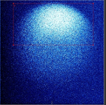
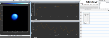
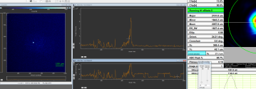
Figure 5(a) shows the fluorescence image of a cloud of ions loaded by applying single pulses of the ablation laser with energies of around , using an axial trap frequency . The ablation laser focus diameter on the beryllium target is estimated to be on the order of . Exact determination of the waist diameter is difficult because the laser has a multimode profile and focussing with a parabolic mirror highly depends on beam quality. Direct creation of ions by ablation from a metallic target has been reported before [28, 29]. We found that pulse energies of 40 to are sufficient to load the trap reliably. This corresponds to a peak intensity of about 0.5 to at the beryllium target’s position. Below a threshold of about , no loading is observed.
The loading is insensitive to photoionization laser power (or absence thereof). The reason for the insensitivity to the photoionization laser is of concern since ions produced directly by the ablation laser are expected to have much larger magnetron radii than ions that are produced in the trap center. To detect and cool the ions, we shine in laser light with a frequency close to to drive the closed cycling transition . We observe a strong fluorescence signal on the EMCCD detector after loading the trap. Figures 5(b) and (c) show images of a large and small cloud of ions after optimization of the imaging system. When continuously laser-cooled, clouds can be trapped for days.
4.2 Demonstration of Doppler cooling
Effective laser cooling in a Penning trap is complicated by the metastable nature of the magnetron motion [30, 31]. The negative energy associated with the magnetron motion makes it hard to cool all three motional modes at the same time. When referring to ‘cooling’ the magnetron motion, we mean reducing its quantum number, reducing the magnetron radius and hence putting energy into the mode rather than removing it. In contrast to many other experiments, we use a single laser beam that has an inclination of with respect to the trap axis, so it interacts with all motional modes.
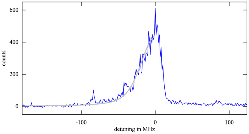
Upon ramping the cooling laser to the red-detuned side of the resonance, we observe a distinctive change in the fluorescence spectrum over time. Directly after loading, the fluorescence is unaffected by the laser frequency over a tuning range of to the red of the resonance. Assuming Doppler broadening, we estimate a temperature in excess of . After cooling, a clear resonance, as shown in figure 6, with a width (FWHM) of can be extracted from fitting a Voigt profile [32] to the red-detuned side of the spectrum. Heating processes lead to a sharp drop of fluorescence on the blue-detuned side of the resonance frequency.
Considering that the natural linewidth of the transition is [33], we deconvolve the Voigt profile with the corresponding Lorentzian lineshape, and derive a Gaussian FWHM of , which we attribute to Doppler broadening. The corresponding temperature is using [34]
| (4) |
The Doppler limit for the cooling transition used is , hence further optimization of the cooling parameters, such as beam pointing, should allow to further decrease the temperature of the particle. By moving the laser beam away from the trap center, an intensity gradient over the radial extent of the ion’s trajectory is created that allows to cool all three modes simultaneously [30, 31]. We also realized cooling of all three modes by applying a red-detuned laser to cool the axial and cyclotron modes efficiently and simultaneously irradiating a sideband drive with frequency (where is the axial and the magnetron frequency) to couple the two modes, thus creating a steady state in which all motional modes are cooled [35].
4.3 Reduction of particle number
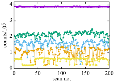
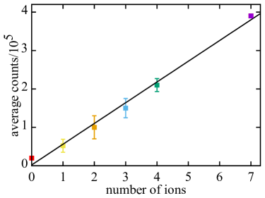
With our current loading scheme, we usually trap a large cloud of ions. Since we plan on using single ions for motional coupling and subsequent steps, we need to reduce the number of particles. Towards that end, we trap a cloud with a high negative voltage on the ring electrode of around . We then decrease the voltage by a factor of 10 to remove the most energetic particles from the trap. After some precooling, we ramp the voltage back to the original value to get a tight confinement of the remaining cloud. We then apply a voltage sequence on the electrodes to adiabatically split the ion cloud and discard a part of it. The remaining cloud is recooled subsequently. After a few of these splitting cycles, we end up with a small cloud. On numerous attempts (see Figure 7), we found a smallest increment in the fluorescence signal which we attribute to a single ion. Figure 7(b) shows a linear relation between the number of ions and counts on the EMCCD camera of counts per ion using an exposure time of and an overall gain of 78 (electron multipler gain and preamplifier of the camera).
5 Prospects and discussion
Now that the trapping infrastructure and several essential steps such as loading, cooling, and detection have been implemented successfully, we pursue the goal of demonstrating motional coupling of two individual ions in separate potential wells in a Penning trap for the first time.
Since it is crucial for the coupling scheme that the axial trap frequencies are equal, our first goal is to demonstrate coupling between two ions in a symmetric potential.
In addition, we are currently testing a proton source trap that will allow proton loading without blocking on-axis access to the trap.
Moreover, we are setting up the associated electronics for work with protons, such as detection tank circuits and amplifiers [22].
Furthermore, we are working towards sub-Doppler cooling of in a Penning trap.
While sideband cooling in a Penning trap has been demonstrated [36], the used ions are amenable to direct sideband cooling using a single laser, as an optical qubit transition is used. For , a Raman process is needed to interact with the motional modes on the single quantum level. Towards that end, the ground state hyperfine splitting must be bridged using two phase-coherent lasers with a frequency difference of around .
This frequency gap is too large to be closed using acousto-optic modulators, as it is common to do in low-field applications.
We have recently demonstrated the use of a pulsed laser [37] to drive motional sideband transitions in [38], an approach which can bridge this big qubit splitting.
On longer timescales, miniaturisation of the coupling trap using established techniques of microfabrication is pursued in order to increase the coupling rate. Together with ground-state cooling, manipulation of the motional states is in reach as well as quantum logic spectroscopy, potentially shortening the preparation time of single antiprotons with spin state detection fidelity of by more than two orders of magnitude [15].
Precision experiments in Penning traps usually utilize the Brown-Gabrielse invariance theorem [39] to determine the free cyclotron frequency of the particle of interest. In precision studies on the p.p.b.-level and below, energy dependent systematic shifts of the eigen-frequencies of the three Penning trap modes need to be characterized and corrected. These shifts arise from trap imperfections due to non-linear terms in the trapping potential, inhomogeneities of the magnetic field, image charge and relativistic shifts, and have been summarized in [40, 19]. Of leading concern are shifts of the modified cyclotron frequency . Here, -shifts, imposed by the weakly bound axial oscillator, constitute a dominant source of systematic uncertainty. The shift imposed by a non-vanishing magnetic bottle term of a slightly inhomogeneous magnetic field is given by
| (5) |
For protons at a typical axial frequency in a magnetic field of [41, 5], the fractional systematic -shift is
| (6) |
where is the axial temperature of the particle. For example in non-compensated g-factor experiments is typically in a range between and , while [5, 41]. Depending on the chosen frequency measurement method, the -scaling can induce a dominant systematic error [41]. With the axial temperature achieved in this work, and by imprinting it to the axial mode of a co-trapped antiproton in advance to a cyclotron frequency measurement, the related cyclotron frequency shift would be suppressed to a level of ppt.
The axial energy exchange between an antiproton and a laser cooled Be-ion is expected to take about .
Using a sideband pulse [42], the axial energy can be translated to cyclotron mode energy, achieving with the trap parameters currently used.
Using this scheme, a single antiproton at , and therefore a particle with a spin-state identification fidelity [9], could be prepared in an effective coupling time of about .
Compared to recent BASE antiproton magnetic moment measurements, this would reduce the effective -mode temperature by about a factor of 5, and the coupling time to thermalize the antiproton by more than a factor of 100.
This advance would eliminate the dominant time-consuming step of the measurement sequence, will enable measurements at significantly improved sampling rate and substantially lower systematic error [41, 5].
Note that the temperature which was achieved for the beryllium cloud above is an ensemble temperature with broadened recoil parameter and therefore increased temperature.
We expect that with a single particle, the axial temperature can be reduced to the Doppler limit, a factor of 40 lower [43].
This will considerably improve the performance of future magnetic moment experiments.
6 Conclusion
We have designed and commissioned a novel cryogenic Penning trap system for ions. We have successfully demonstrated ablation loading, Doppler cooling, and reduction of the number of ions down to a single particle which has been detected unambiguously. We have outlined the next steps towards motional coupling and sympathetic cooling of two ions that can be generalized to arbitrary charged ions. We anticipate a high impact of the sympathetic cooling scheme on precision measurements in Penning traps, such as - or -factor measurements on antiprotons and protons, molecular ions or other systems that are not amenable for direct laser cooling.
References
References
- [1] Lüders G 1957 Annals of Physics 2 1–15 ISSN 0003-4916 URL http://www.sciencedirect.com/science/article/pii/0003491657900325
- [2] Greenberg O W 2002 Physical Review Letters 89 231602 URL https://link.aps.org/doi/10.1103/PhysRevLett.89.231602
- [3] Smorra C, Blessing P E, Borchert M J, Devlin J A, Harrington J A, Higuchi T, Morgner J, Nagahama H, Sellner S, Bohman M A, Mooser A H, Schneider G L, Schön N, Wiesinger M, Blaum K, Matsuda Y, Ospelkaus C, Quint W, Walz J, Yamazaki Y and Ulmer S 2018 Hyperfine Interactions 239 47 ISSN 1572-9540 URL https://doi.org/10.1007/s10751-018-1507-1
- [4] Higuchi T, Harrington J A, Borchert M J, Blessing P E, Devlin J A, Morgner J, Sellner S, Smorra C, Bohman M A, Mooser A H, Schneider G L, Schön N, Wiesinger M, Blaum K, Matsuda Y, Ospelkaus C, Quint W, Walz J, Yamazaki Y and Ulmer S 2018 Hyperfine Interactions 239 27 ISSN 1572-9540 URL https://doi.org/10.1007/s10751-018-1499-x
- [5] Schneider G, Mooser A, Bohman M, Schön N, Harrington J, Higuchi T, Nagahama H, Sellner S, Smorra C, Blaum K, Matsuda Y, Quint W, Walz J and Ulmer S 2017 Science 358 1081–1084 ISSN 0036-8075, 1095-9203 URL http://science.sciencemag.org/content/358/6366/1081
- [6] Ulmer S, Smorra C, Mooser A, Franke K, Nagahama H, Schneider G, Higuchi T, Van Gorp S, Blaum K, Matsuda Y, Quint W, Walz J and Yamazaki Y 2015 Nature 524 196–199 ISSN 1476-4687 URL https://www.nature.com/articles/nature14861
- [7] Häffner H, Beier T, Djekić S, Hermanspahn N, Kluge H J, Quint W, Stahl S, Verdú J, Valenzuela T and Werth G 2003 The European Physical Journal D - Atomic, Molecular, Optical and Plasma Physics 22 163–182 ISSN 1434-6060, 1434-6079 URL http://link.springer.com/article/10.1140/epjd/e2003-00012-2
- [8] Borchert M, Blessing P, Devlin J, Harrington J, Higuchi T, Morgner J, Smorra C, Wursten E, Bohman M, Wiesinger M, Mooser A, Blaum K, Matsuda Y, Ospelkaus C, Quint W, Walz J, Yamazaki Y and Ulmer S 2019 Physical Review Letters 122 043201 URL https://link.aps.org/doi/10.1103/PhysRevLett.122.043201
- [9] Smorra C, Mooser A, Besirli M, Bohman M, Borchert M J, Harrington J, Higuchi T, Nagahama H, Schneider G L, Sellner S, Tanaka T, Blaum K, Matsuda Y, Ospelkaus C, Quint W, Walz J, Yamazaki Y and Ulmer S 2017 Physics Letters B 769 1–6 ISSN 0370-2693 URL http://www.sciencedirect.com/science/article/pii/S0370269317302113
- [10] Heinzen D J and Wineland D J 1990 Physical Review A 42 2977 URL http://link.aps.org/doi/10.1103/PhysRevA.42.2977
- [11] Wineland D J, Monroe C R, Itano W M, Leibfried D, King B E and Meekhof D M 1998 J. Res. NIST 103 259 URL http://http://nvl.nist.gov/pub/nistpubs/jres/103/3/j33win.pdf
- [12] Brown K R, Ospelkaus C, Colombe Y, Wilson A C, Leibfried D and Wineland D J 2011 Nature 471 196–199 ISSN 1476-4687 URL https://www.nature.com/articles/nature09721
- [13] Harlander M, Lechner R, Brownnutt M, Blatt R and Hansel W 2011 Nature 471 200–203 ISSN 0028-0836 URL http://dx.doi.org/10.1038/nature09800
- [14] Niemann M, Paschke A G, Dubielzig T, Ulmer S and Ospelkaus C 2013 CPT test with (anti)proton magnetic moments based on quantum logic cooling and readout CPT and Lorentz Symmetry (WORLD SCIENTIFIC) pp 41–44 ISBN 978-981-4566-42-1 URL http://www.worldscientific.com/doi/abs/10.1142/9789814566438_0011
- [15] Smorra C, Blaum K, Bojtar L, Borchert M, Franke K, Higuchi T, Leefer N, Nagahama H, Matsuda Y, Mooser A, Niemann M, Ospelkaus C, Quint W, Schneider G, Sellner S, Tanaka T, Van Gorp S, Walz J, Yamazaki Y and Ulmer S 2015 The European Physical Journal Special Topics 224 1–54 ISSN 1951-6355, 1951-6401 URL http://link.springer.com/10.1140/epjst/e2015-02607-4
- [16] Cornejo J M, Gutiérrez M J, Ruiz E, Bautista-Salvador A, Ospelkaus C, Stahl S and Rodríguez D 2016 International Journal of Mass Spectrometry 410 22–30 ISSN 1387-3806 URL http://www.sciencedirect.com/science/article/pii/S1387380616302172
- [17] Bohman M, Mooser A, Schneider G, Schön N, Wiesinger M, Harrington J, Higuchi T, Nagahama H, Smorra C, Sellner S, Blaum K, Matsuda Y, Quint W, Walz J and Ulmer S 2018 Journal of Modern Optics 65 568–576 ISSN 0950-0340 URL https://doi.org/10.1080/09500340.2017.1404656
- [18] Larson D J, Bergquist J C, Bollinger J J, Itano W M and Wineland D J 1986 Physical Review Letters 57 70–73 URL https://link.aps.org/doi/10.1103/PhysRevLett.57.70
- [19] Brown L S and Gabrielse G 1986 Reviews of Modern Physics 58 233–311 URL http://link.aps.org/doi/10.1103/RevModPhys.58.233
- [20] Sellner S, Besirli M, Bohman M, Borchert M J, Harrington J, Higuchi T, Mooser A, Nagahama H, Schneider G, Smorra C, Tanaka T, Blaum K, Matsuda Y, Ospelkaus C, Quint W, Walz J, Yamazaki Y and Ulmer S 2017 New Journal of Physics 19 083023 ISSN 1367-2630 URL https://doi.org/10.1088%2F1367-2630%2Faa7e73
- [21] Bowler R, Warring U, Britton J W, Sawyer B C and Amini J 2013 Review of Scientific Instruments 84 033108–033108–6 ISSN 00346748 URL http://rsi.aip.org/resource/1/rsinak/v84/i3/p033108_s1
- [22] Nagahama H, Schneider G, Mooser A, Smorra C, Sellner S, Harrington J, Higuchi T, Borchert M, Tanaka T, Besirli M, Blaum K, Matsuda Y, Ospelkaus C, Quint W, Walz J, Yamazaki Y and Ulmer S 2016 Review of Scientific Instruments 87 113305 ISSN 0034-6748, 1089-7623 URL http://scitation.aip.org/content/aip/journal/rsi/87/11/10.1063/1.4967493
- [23] Wilson A C, Ospelkaus C, VanDevender A P, Mlynek J A, Brown K R, Leibfried D and Wineland D J 2011 Applied Physics B 105 741–748 ISSN 1432-0649 URL https://doi.org/10.1007/s00340-011-4771-1
- [24] Lo H Y, Alonso J, Kienzler D, Keitch B C, de Clercq L E, Negnevitsky V and Home J P 2014 Applied Physics B 114 17–25 ISSN 1432-0649 URL https://doi.org/10.1007/s00340-013-5605-0
- [25] Hannig S, Mielke J, Fenske J A, Misera M, Beev N, Ospelkaus C and Schmidt P O 2018 Review of Scientific Instruments 89 013106 ISSN 0034-6748 URL https://aip.scitation.org/doi/10.1063/1.5005515
- [26] Colombe Y, Slichter D H, Wilson A C, Leibfried D and Wineland D J 2014 Optics Express 22 19783–19793 ISSN 1094-4087 URL https://www.osapublishing.org/oe/abstract.cfm?uri=oe-22-16-19783
- [27] Marciniak C D, Ball H B, Hung A T H and Biercuk M J 2017 Optics Express 25 15643–15661 ISSN 1094-4087 URL https://www.osapublishing.org/abstract.cfm?uri=oe-25-14-15643
- [28] Chichkov B N, Momma C, Nolte S, von Alvensleben F and Tünnermann A 1996 Applied Physics A 63 109–115 ISSN 1432-0630 URL https://doi.org/10.1007/BF01567637
- [29] Zimmermann K, Okhapkin M V, Herrera-Sancho O A and Peik E 2012 Applied Physics B 107 883–889 ISSN 0946-2171, 1432-0649 URL https://link.springer.com/article/10.1007/s00340-012-4884-1
- [30] Itano W M and Wineland D J 1982 Physical Review A 25 35–54 URL http://link.aps.org/doi/10.1103/PhysRevA.25.35
- [31] Thompson R C and Papadimitriou J 2000 Journal of Physics B: Atomic, Molecular and Optical Physics 33 3393–3405 ISSN 0953-4075, 1361-6455 URL http://iopscience.iop.org/0953-4075/33/17/317
- [32] Olivero J J and Longbothum R L 1977 Journal of Quantitative Spectroscopy and Radiative Transfer 17 233–236 ISSN 0022-4073 URL http://www.sciencedirect.com/science/article/pii/0022407377901613
- [33] Andersen T, Jessen K A and Sørensen G 1969 Physical Review 188 76–81 URL https://link.aps.org/doi/10.1103/PhysRev.188.76
- [34] Foot C J 2005 Atomic Physics Oxford Master Series in Atomic, Optical and Laser Physics (Oxford: Oxford University Press) ISBN 0-19-850696-1
- [35] Dehmelt H G 1976 Nature 262 777 ISSN 1476-4687 URL https://www.nature.com/articles/262777a0
- [36] Goodwin J F, Stutter G, Thompson R and Segal D 2016 Physical Review Letters 116 143002 URL https://link.aps.org/doi/10.1103/PhysRevLett.116.143002
- [37] Hayes D, Matsukevich D N, Maunz P, Hucul D, Quraishi Q, Olmschenk S, Campbell W, Mizrahi J, Senko C and Monroe C 2010 Physical Review Letters 104 140501 URL http://link.aps.org/doi/10.1103/PhysRevLett.104.140501
- [38] Paschke A G, Zarantonello G, Hahn H, Lang T, Manzoni C, Marangoni M, Cerullo G, Morgner U and Ospelkaus C 2019 Physical Review Letters 122 123606 URL https://link.aps.org/doi/10.1103/PhysRevLett.122.123606
- [39] Brown L S and Gabrielse G 1982 Physical Review A 25 2423–2425 URL http://link.aps.org/doi/10.1103/PhysRevA.25.2423
- [40] Ketter J, Eronen T, Höcker M, Streubel S and Blaum K 2014 International Journal of Mass Spectrometry 358 1–16 ISSN 1387-3806 URL http://www.sciencedirect.com/science/article/pii/S1387380613003722
- [41] Smorra C, Sellner S, Borchert M J, Harrington J A, Higuchi T, Nagahama H, Tanaka T, Mooser A, Schneider G, Bohman M, Blaum K, Matsuda Y, Ospelkaus C, Quint W, Walz J, Yamazaki Y and Ulmer S 2017 Nature 550 371–374 ISSN 0028-0836 URL https://www.nature.com/nature/journal/v550/n7676/full/nature24048.html
- [42] Cornell E A, Weisskoff R M, Boyce K R and Pritchard D E 1990 Physical Review A 41 312–315 URL https://link.aps.org/doi/10.1103/PhysRevA.41.312
- [43] Sawyer B C, Britton J W and Bollinger J J 2014 arXiv:1401.0672 [physics, physics:quant-ph] URL http://arxiv.org/abs/1401.0672