Performance analysis of IEEE 802.11ax heterogeneous network in the presence of hidden terminals
Abstract
Performance improvement has been among the foci of all previous amendments of IEEE 802.11 protocol. In addition, the draft high efficiency (HE) amendment IEEE 802.11ax, proposed by TGax, aims at increasing network performance. One of the main obstacles to improving spectral and power efficiency is the presence of hidden terminals which degrade throughput, in particular in uplink transmission. IEEE 802.11ax does provide mechanisms such as trigger based uplink transmission that mitigate this degradation to some extent, but are incapable of eliminating it, esp. at high arrival rates. To combat the hidden terminal problem, we propose to increase the carrier sensing threshold (CSTH) of STAs during association with an HE access point. Our results confirm that the proposed mechanism can lead to significant reduction of collision probability in uplink transmission.
1 Introduction
The ubiquitous IEEE 802.11 standard has undergone several revisions or amendments that aim to improve its performance, in particular network throughput, by augmenting the capabilities of its physical (PHY) and medium access control (MAC) layers. In all cases, however, the presence of hidden nodes/terminals has been among the major factors leading to degraded network throughput and, consequently, spectrum inefficiency [2]. Although the Ready-to-send (RTS)/Clear-to-send (CTS) handshake mostly succeeds in avoiding hidden terminal problem in downlink transmission, it cannot do the same for the uplink direction where hidden node transmissions lead to collision at the Access Point (AP). Each collision leads to retransmission and, eventually, to dropping the packet which can severely limit the throughput of the network.
One of the recent attempts to enhance spectral and power efficiency is the IEEE 802.11ax protocol which is specifically targeting dense WiFi deployment environments [3] [4]. The development of this version of the standard was guided by the fact that well known techniques such as exponential backoff, inter-frame spacing, and RTS/CTS tend to reduce spectrum efficiency of Enhanced Distributed Channel Access (EDCA). At the same time, the multi-user multiple-input multiple-output (MU-MIMO) technology, which has been successful for downlink transmissions [5], should be extended to the uplink direction as well.
Furthermore, the 802.11ax revision puts additional focus on the coexistence of new High Efficiency (HE) devices with legacy, non-HE ones. This is due to the long adoption time for HE protocols during which both HE and non-HE devices will coexist, and non-HE devices may experience significant performance degradation. To ensure access fairness and backward compatibility, the new standard will rely on EDCA channel access in conjunction with Orthogonal Frequency Division Multiple Access (OFDMA). As the result, both the AP and individual stations (STAs) will compete for channel using EDCA channel access. When the AP gains access, it will work as a central controller which will solicit CSI reports and buffer state information from peripheral STAs. IN addition, the AP will allocate resources for MU transmission in both uplink and downlink directions, and initiate OFDMA random access procedure for STAs. When a non-HE STA wins the contention, a single user transmission will take place. This limitation has been removed in a recently proposed multi-user access protocol for uplink [6] which allows multiple legacy STAs to transmit in uplink direction using MU-MIMO technique.
To eliminate hidden node problem in uplink MU-MIMO transmission, IEEE 802.11ax draft protocol introduces the so-called trigger-based uplink transmission [7]. Yet even that mechanism does not succeed in eliminating hidden node interference for legacy devices, and the impact of hidden nodes in UL-MIMO transmission remains a major concern. This problem has been discussed, and a possible solution has been proposed, in a a recent conference paper [1]. The current report is a revised and extended version of that conference paper, in which we evaluate major performance metrics of an IEEE 802.11ax heterogeneous network in presence of hidden terminals; propose a simple solution to reduce or even eliminate the impact of hidden terminals by increasing the Carrier Sensing Threshold (CSTH) from -82dBm to -73dBm during association of STAs with AP; and propose and discuss some modifications in the draft IEEE 802.11ax protocol.
The rest of the paper is organized as follows: In Section 2, we discuss the uplink access technique in IEEE 802.11ax amendment. Section 3 discusses and models the impact of hidden terminals as well as possible ways in which the impact of hidden nodes can be eliminated and the associated modifications to the draft standard specification. The simulation results are discussed in Section 4, followed by conclusion in Section 5.
| Abbreviation | Description | Abbreviation | Description |
|---|---|---|---|
| AC | Access Category | AIFS | Arbitration Inter-frame Spacing |
| A-MSDU | Aggregate MSDU | BO | Backoff |
| CSI | Channel State Information | CTS | Clear to Send |
| CW | Contention Window | DCF | Distributed Coordination Function |
| DIFS | DCF Inter-frame Spacing | EDCA | Enhanced Distributed Channel Access |
| EDCAF | EDCA Function | G-ACK | Group ACK |
| G-CTS | Group CTS | HPG | High Priority traffic Group |
| LPG | Low priority traffic Group | MIMO | Multiple Input Multiple Output |
| MPDU | MAC Protocol Data Unit | MPR | Multi Packet Reception |
| MSDU | MAC Service Data Unit | MU | Multi User |
| NDP | Null Data Packet | NDPA | NDP Announcement |
| PPDU | PHY Protocol Data Unit | RTS | Ready to Send |
| SIFS | Short Inter-frame Spacing | VHT | Very High Throughput |
| TXOP | Transmission opportunity | AIFSN | AIFS number Throughput |
| LST | Laplace-Stieltjes transform | NDP | Null Data Packet |
| PGF | Probability generating function | MU-MIMO | Multi-user MIMO |
| DL-MIMO | Downlink MIMO | OFDMA | Orthogonal frequency division multiple access |
| A-MPDU | Aggregate MPDU | STA | Station |
| AP | Access point |
2 Uplink transmission in IEEE 802.11ax protocol
In an IEEE 802.11ax-compliant network, multi-user uplink transmission is performed under control of the AP. A new control frame format, known as the trigger frame, contains the information that identifies the STAs that will transmit uplink multi-user PHY layer packets, hereafter referred to as PHY layer protocol data units (PPDUs). Trigger-based uplink transmission requires the AP to have the buffer state information for all STAs that intend to transmit. This information can be supplied by the STAs themselves (although the specification does not define how exactly is this to be done), or the AP can explicitly request it by transmitting a trigger frame. Nonetheless, we assume that the STA must access the medium through EDCA procedure, even if only to transmit buffer state information to the AP.
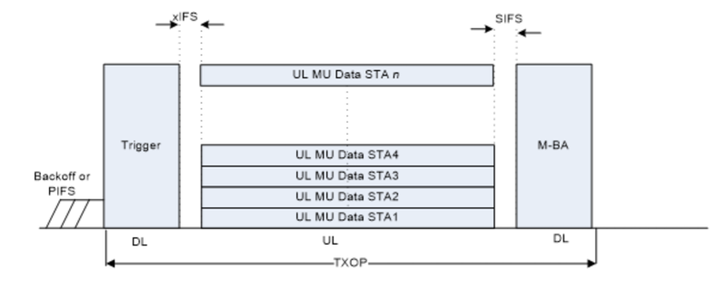
An UL MU transmission is initiated as an immediate response to a DL trigger frame sent by the AP, as shown in Fig. 2. The trigger frame allocates resources for the intending STAs. The frame exchange initiated by the trigger frame is considered successful if the AP receives UL MU data correctly from at least one STA. AP then acknowledges the successful receipt of all MPDUs by sending the so-called Multi-block acknowledgement (M-BA).
Before responding to a trigger frame, the STA performs physical (ED) as well as virtual (NAV) carrier sensing if trigger frame indicates to do so before UL MU transmission [8].
The multi-user uplink transmission protocol for legacy devices is discussed in detail in [6].
3 Impact of hidden nodes
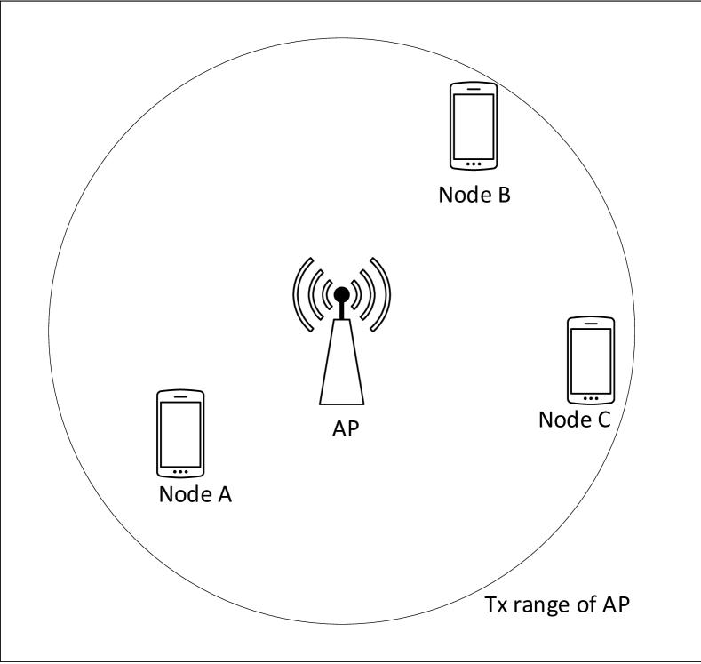
To discuss the impact of hidden nodes, let us consider a heterogeneous network consisting of only one HE AP and a number of HE and legacy (i.e., non-HE) STAs in an isolated basic service subsystem (BSS) as shown in Fig. 4. Assuming that other BSS(s) in the vicinity operate on different primary channel(s), there will be no interference from the nearby BSS. Since all the nodes are associated with the AP, we can safely assume that all the nodes are within the transmission range of the AP. Therefore, there are no hidden terminals from the AP point of view and no associated hidden terminal problem. However, in the AP-initiated uplink multi-user communication, there may be concurrent transmissions from other STAs, which means that the trigger frame itself is vulnerable to collision. In other words, the only transmission initiated by the AP that may suffer a collision is the trigger frame. In addition, as soon as the STAs receive trigger frame or MU-RTS, they will update their NAVs accordingly. Therefore, data, CTS or ACK/G-ACK messages from HE devices transmitted in the uplink direction will not suffer any collision.
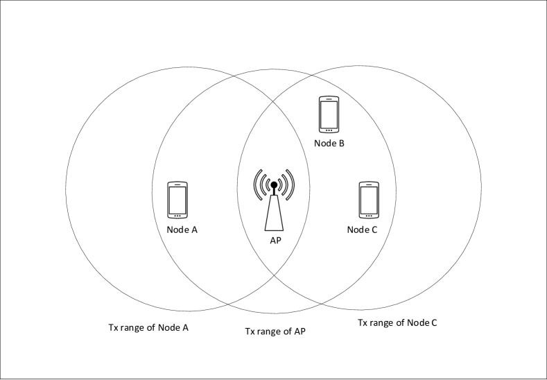
However, due to the coexistence of legacy devices, uplink SU or MU transmission from legacy devices cannot avoid the hidden terminal problem. As shown in Fig. 4, when a node (A) initiates an RTS in the uplink, assuming that the transmission range of the APP and all other nodes is the same, nodes B and C effectively act as hidden terminals for node A. Therefore, any ongoing RTS transmission between node A and AP is not noticed by node B or node C. If another node, say, node C, initiates a transmission during an ongoing RTS transmission between node A and AP, or within the SIFS period before the CTS transmission by AP, the AP will see those packets as collisions. As the result, both node A and node C will not receive their CTS from AP which will cause both nodes A and C to increase their contention windows and initiate retransmissions.
3.1 Modeling hidden nodes
To model the impact of hidden nodes, we will assume that STA traffic can be categorized in four priority categories (). Furthermore, we assume that each traffic category will contend for medium access using its own EDCA function. Packet arrival for traffic class is assumed to follow a Poisson process with arrival rate of . Durations of MPDU, RTS, CTS, BA and Trigger frames, denoted by and , respectively, are expressed as integer multiples of slots (we assume a time slot of s). Durations of and SIFS periods are denoted by and , respectively (in slots). Channel state is modeled via bit error rate so that the probability that a RTS or CTS frame will not be corrupted by channel noise is . Probability that data or BA frames will not experience any corruption due to channel noise is denoted as . In the two last equations, and denote the bit count in RTS, CTS, BA and MPDU frames, respectively.
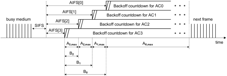
The behaviour of different ACs during backoff under EDCA is shown in Fig. 2. Before can begin backoff countdown, the medium must be idle for a period of without interruption. can be expressed as where is arbitration inter frame spacing number for traffic category . Since priority increases with , no transmission is possible during the period . Initial values of the freezing counters are set to be .
Duration of time periods in which traffic class and higher can access the medium is denoted as and their maximum values are
| (1) |
where is the maximum number of backoff states for .
The initial value of the backoff counter is uniformly distributed over the interval , where is the contention window for during backoff phase . The maximum number of backoff states in backoff phase is = . For backoff phase 0, the number of backoff states is set to . We can express in terms of as
| (2) |
If denotes the number of nodes within the transmission range of a STA, we can relate the probability that a time slot will be idle during the interval and the channel access probability as
| (3) |
Probability of successful transmission for a node, without considering the impact of hidden nodes, can be written as
| (4) |
The vulnerable period, i.e., the period during which a collision can take place at the AP, for a single user uplink transmission is . By the same token, the vulnerable period for an UL MU transmission is .
Let be the number of nodes of traffic category hidden from a transmitting node. The probability that a hidden node will not transmit in any time slot during vulnerable period can be written as
| (5) |
where is the transmission probability for traffic category .
Then, the probability of no collision from the hidden nodes during the entire vulnerable period is
| (6) |
where is the trigger transmission probability of AP to initiate multi-user uplink transmission. This probability is equal to the downlink MU TXOP sharing probability given by
| (7) |
as discussed in [6].
Finally, probability of successful transmission in the presence of hidden nodes can be expressed as , where is the probability of successful transmission but without any hidden node.
3.2 Eliminating the hidden node problem
Due to rapid growth of diverse and dense deployment environments, IEEE 802.11ax networks can be expected to contain an ever increasing number (and, consequently) density of both APs and STAs. These environments are commonly characterized by hidden terminal problems and the resulting increase in interference from the nearby WLANs, increase in collision rate, and decrease of channel utilization. A prpmising technique seems to be to increase the carrier sensing threshold (CSTH) which will allow multiple STAs and/or APs to transmit simultaneously, which will counter the performance degradation caused by collisions and improve spatial reuse. At the same time, increasing CSTH in a coexistence scenario may lead to asymmetric hidden node problem in which legacy STAs will be severely deprived of the chances of channel access due to the HE STAs virtually taking over the shared channel [11].
| Parameters | Numerical values |
|---|---|
| Bit error rate, BER | bits/s |
| Duration of Time slot, | 9 |
| Minimum PHY header | 40 |
| Maximum PHY header | 52 |
| DCF Inter-frame space duration, DIFS | |
| MPDU length | 11454 |
| Short Inter-frame space duration, SIFS | |
| MAC header length | 36 bytes |
| Request to send, RTS | 20 bytes |
| Clear to send, G-CTS | 14 bytes |
| Acknowledgement, G-ACK | 32 bytes |
| Maximum retry limit , R | 7 |
| Max. number of antennas in AP, | 4 |
| Number of antennas in STA | 1 |
| Bandwidth | 80 MHz |
| OFDM symbol duration | 4 |
| Number of bits per OFDM symbol duration | 1560 |
| Modulation and Coding scheme, MCS | 9 |
| Maximum backoff stages | |
| Arbitration inter frame space, AIFS | |
| Minimum contention window size | |
| TXOP duration limit |
We argue that the hidden terminal problem can be solved by increasing the carrier sensing threshold (CSTH) of all STAs during association with a HE AP. This will effectively reduce the transmission range of the AP and restrict the number of STAs that can associate with the AP to those physically closer to the AP. However, during usual transmission process, the carrier sensing threshold will remain at the value recommended by the standard for all STAs. In this way we can ensure that all STAs within the BSS are also within the transmission range of each other.
This approach allows us to solve the hidden node problem in the uplink transmission and, furthermore, to reduce the transmit power of the AP which will make the AP more energy efficient. However, it may also lead to inter-BSS interference issue. Namely, if a STA has a larger transmission range, it will generate interference to the STAs of the nearby BSS and even attempt to set the NAV of the STAs belonging to other BSS. Fortunately, this interference can easily be eliminated if the adjacent BSSs are forced to operate on different primary channels and if we restrict the transmission from a foreign BSS in setting the NAV of a STA.
In light of this discussion, we propose the following modifications in the draft specification:
-
•
The CSTH of all STAs during association with HE AP will be increased while CSTH of all STAs during normal transmission process will remain same as legacy STAs.
-
•
Two adjacent BSSs will operate in two different primary channels.
-
•
The NAV of a STA will be set only by the transmission of another STA within the same BSS. If a STA receives transmission from another STA which does not belong to same BSS as the receiving STA, NAV will not be updated.
4 Simulation Result and Discussion
To simulate the MAC layer of IEEE 802.11ax protocol, we have developed an event-driven simulator in Matlab.
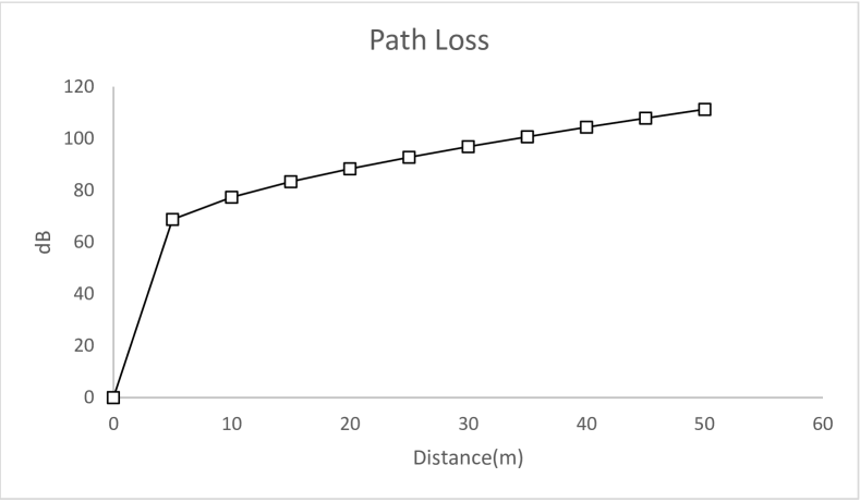
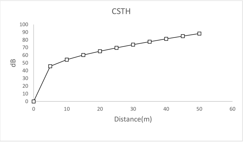
We assume an indoor environment with a single AP and a number of STAs placed randomly on the same floor. We have used the 3GPP indoor femto pathloss (PL) model, as recommended for IEEE 802.11ax standard, as shown in Fig. 6 where pathloss exponent is 2, a linear attenuation for walls is 0.5 dB/m, and 4 dB is assumed to model the shadowing effect in indoor environment.
We assume transmit power level of 23 dBm (200 mW) and initial carrier sensing threshold of -82 dBm. The concentration of the nodes is controlled so that the AP has always 24 nodes associated with it. For each simulation setup, when we increase the carrier sensing threshold of STAs during association process, the transmission range of AP is actually reduced. Therefore, we increase the concentration of STA to ensure that we have same number of STAs associated with AP.
We further assume that the CSTH of all STAs during usual transmission process remains -82 dBm.
The simulation is run with uniformly varying load intensity for each node and all traffic categories. Each simulation is run for 1 second and the performance metrics are averaged over 10 runs.
We assume that our VHT PPDU has one MPDU which contains an A-MSDU originating from the LLC layer. The size of the A-MSDU is limited by the maximum size of MPDU which is 11454 octets. Throughout the evaluation we treat an MPDU as a packet so that the arrival of a packet means the arrival of an MPDU to the queue.
Our network has a bandwidth of 80 MHz having 234 usable subcarriers. A 256 QAM modulation with 5/6 coding scheme allows 1560 bits to be transmitted per OFDM symbol duration of 4 with long guard interval.
Other pertinent parameters for the model are shown in Table 2.
In this setup, we evaluate the performance of the network in three different scenarios. In the first case, we look at the performance of the network under varying packet arrival rate in the presence of hidden terminals. In the second case, we vary the packet arrival rates without hidden terminals. Lastly, we gradually increase the carrier sensing threshold during the association process for a specific packet arrival rate (4800 packets/sec) and evaluate the performance of the network.
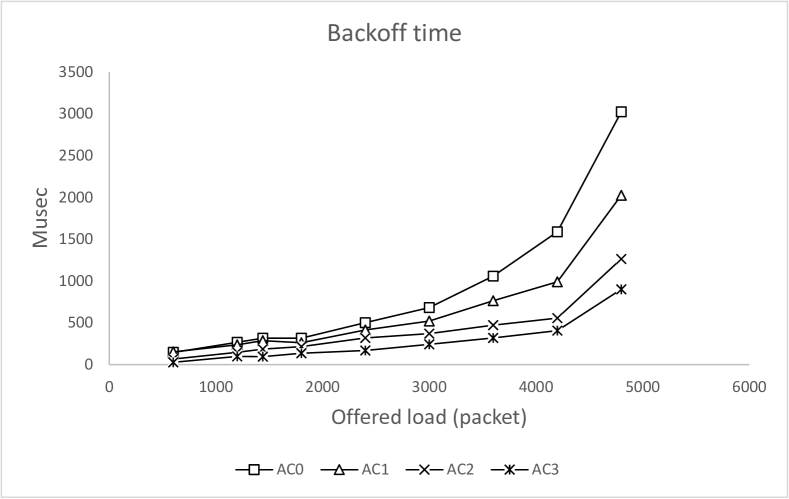
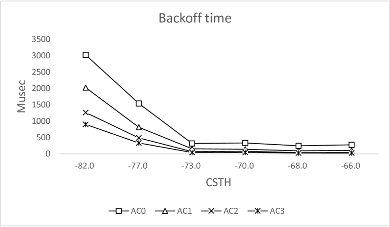
Figs. 9, 9, and 9 shows the backoff time for the scenarios outlined above. The backoff times for all traffic categories gradually increase with the increase of packet arrival rates in presence of hidden terminal as shown in Fig. 9. Although multiple uplink transmissions take place, due to collision from hidden terminals we observe a steady increase in backoff time.
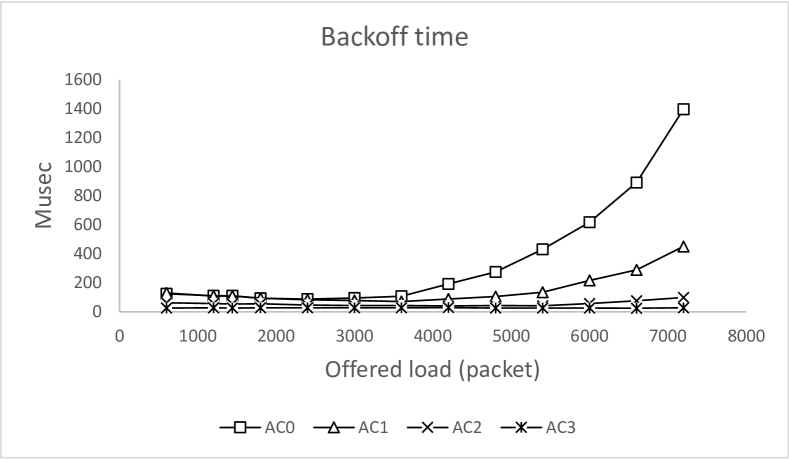
However, in the absence of hidden terminals, the backoff time gradually decreases slightly at low load condition (up to 3600 packets/sec) as shown in Fig. 9. This decrease is due to multi-user uplink transmission. During multi-user uplink transmission, Namely, when a primary STA gets a transmission opportunity (TXOP), secondary STAs share the TXOP with the primary STA even if those secondary STAs are in backoff process. Those transmission opportunities of secondary STAs reduce the effective backoff time as more and more secondary STAs get transmission opportunities without going through the full backoff process, and consequently average backoff time decreases. Since only four STAs can transmit at a time in uplink direction, with the increase of packet arrival rate (above 3600 packets/sec), many STAs need to wait for the medium for a longer time and consequently the backoff time increases, as shown in Fig. 9.
At a packet arrival rate of 4800 packets/sec, the backoff time in the presence of hidden terminals is almost 10 times higher than without them. Also the backoff time for lower priority traffic increases at a faster rate than that of higher priority traffic because, at higher packet arrival rate, more higher priority traffic gets the TXOP sharing opportunity and lower priority traffic needs to wait longer to access the medium.
Finally, the variation of backoff time with the increase in carrier sensing threshold is shown in Fig. 9. We observe that at CSTH of -73dBm, the backoff time of all traffic categories are same as the backoff time of STAs without hidden terminals.
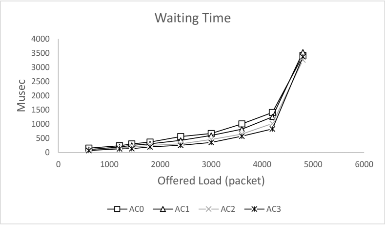
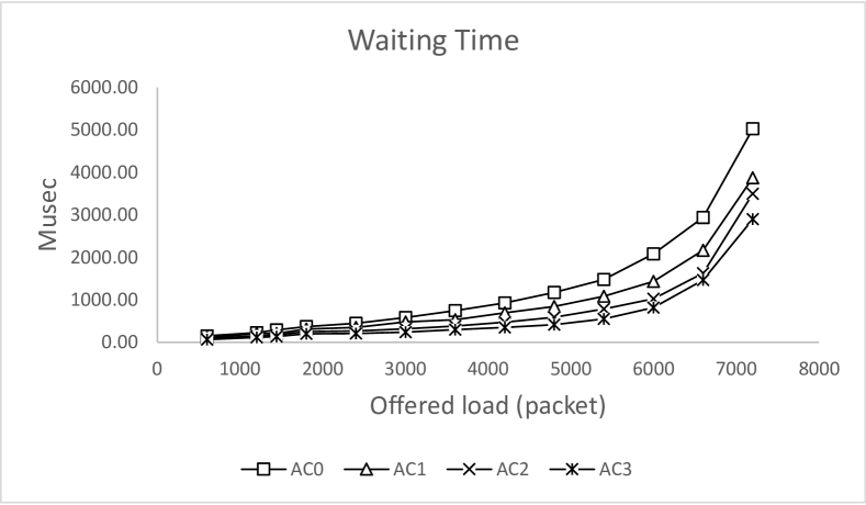
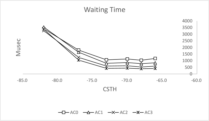
Waiting time is the time a packet needs to wait in the queue before starting the backoff process. Figs. 12, 12, and 12 show the waiting time in three different scenarios. As shown in Figs. 12 and 12, the waiting time gradually increases with the increase of packet arrival rate. However, the waiting time of a packet in presence of hidden terminal is much higher than the waiting time of a packet without hidden terminals. The decrease of waiting time with the increase of CSTH is shown in Fig. 12.
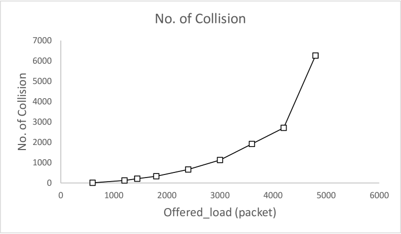
The number of collisions due to hidden terminal(s) for an existing CSTH is shown in Fig. 14. At low packet arrival rate, collision probability is very low on account of longer inter packet arrival time and SU packet transmission. In this case, two transmissions from nodes which are hidden to each other rarely overlap. In addition, vulnerable time for collisions due to hidden node is shorter for SU transmission, and inter-packet arrival time is long enough to complete the transmission of RTS/CTS signaling.
When the packet arrival rate increases, the inter-packet arrival time decreases and more transmissions overlap which increases the collision rate at the AP. Collisions of RTS/CTS frames with transmissions from hidden nodes lead to retransmissions which increases the collision rate even further. This effect may be observed even at higher packet arrival rate, where probability of simultaneous transmission from the hidden node groups and, consequently, the collision probability both become very high.
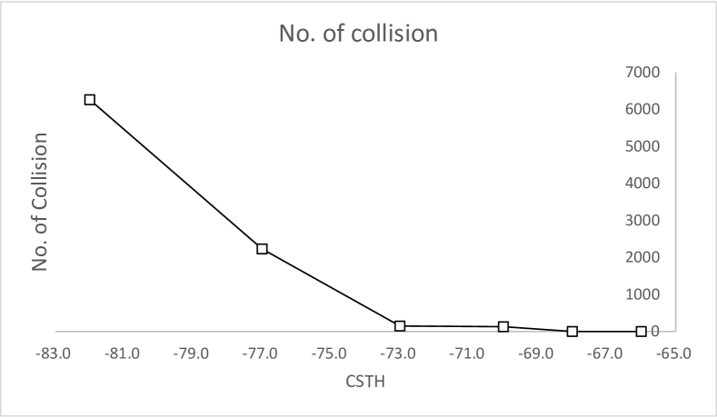
Fig. 14 shows the number of collisions as the function of carrier sensing threshold of STAs during the association process. As CSTH increases, the number of collision decreases. If CSTH is set at -73dBm, the number of collisions becomes very low; still, from Fig. 6 we observe that the corresponding transmission radius of AP is around 30 meters. This observation confirms our argument that in a densely deployed environment, the concentration of APs need to be very high so that all nodes within the transmission range of an AP can hear each other. It also confirms the validity of our approach, namely that increasing the CSTH of STAs during association with AP will reduce or even eliminate the impact of hidden nodes.
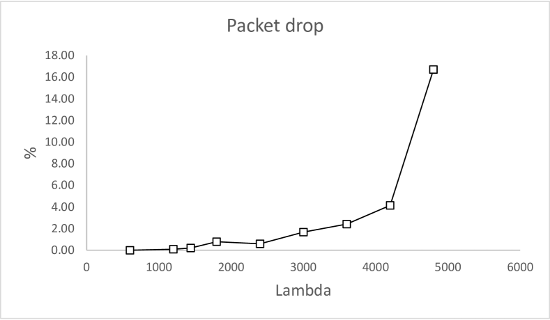
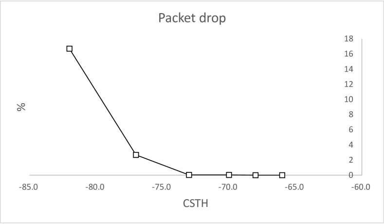
We note that, in our simulations, we assume that after a collision is detected, colliding packets are retransmitted if the retry limit is not reached. Otherwise, the packets are dropped. Fig. 16 shows that, in the presence of hidden terminals, the packet drop is very low at low range of offered load values (2400 packets/sec). However, with the increase of packet arrival rate, packet drop increases and becomes as high as 16% at an arrival rate of 4800 packets/sec in the presence of hidden terminals. Thus, hidden terminals severely impact the performance of the network at high load condition. At CSTH of -73dBm the packet drop is almost zero as shown from Fig. 16.
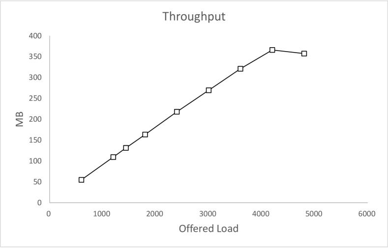
Network throughput is severely impacted by collisions due to hidden terminals. From Fig. 19 we observe that, at an arrival rate of 4200 packets/sec, we achieve highest network throughput of about q366 Mbps. The network throughput at corresponding arrival rate without hidden terminal is 383 Mbps. This deviation of throughput due to hidden terminal is due to longer waiting time, longer backoff time and larger number of retransmissions.
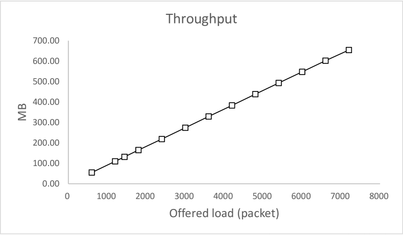
If we further increase the packet arrival rate (4800 packets/sec), the network throughput drops to 357 Mbps as all packets can not be transmitted due to collision and eventually, packets are dropped. However, without hidden terminal problem, network throughput linearly increases with the increase of packet arrival rate as shown in Fig. 19. The network throughput at an arrival rate of 4800 packets/sec reaches about 438 Mbps without hidden nodes which is 23% higher than the throughput achieved with hidden terminal scenario.
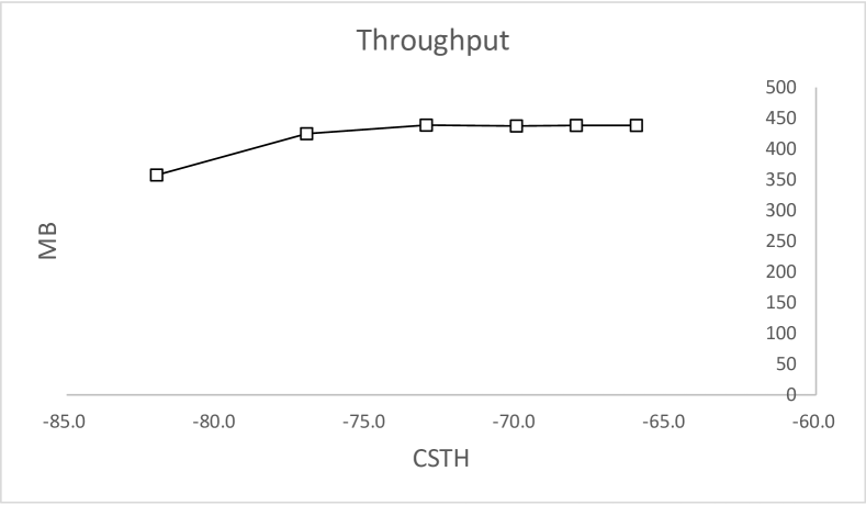
We also observe that in absence of hidden terminals, the network can sustain larger packet arrival rate of even 7200 packets/sec and a high throughput of 655 Mbps can be achieved. With the increase of CSTH from -82dBm to -73dBm at an arrival rate of 4800 packets/sec, the throughput of the network with hidden terminals increases from 357 Mbps to 438 Mbps which is about the same as the throughput obtained in the network without hidden terminals.
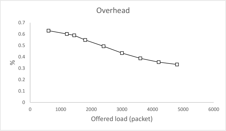
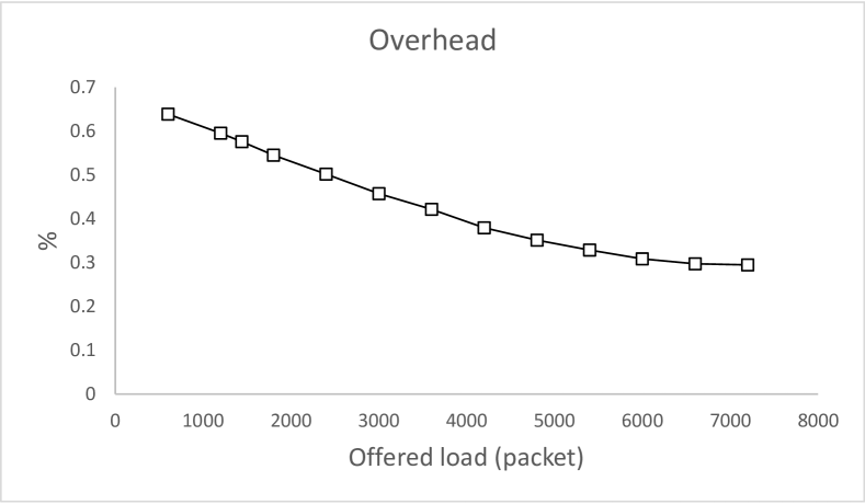
Overhead is calculated as the ratio of time required to transmit control signals to data packet. Figs. 21 and 21 show a comparison of MAC overhead in presence of hidden terminal and without hidden terminal scenarios. At low packet arrival rate, most of the time STAs initiate RTS/CTS controlled single user transmission individually. As a result, the overhead for a data packet is much higher. As the packet arrival rate increases, more STAs start MU transmission where data packets and control signals are simultaneously transmitted from multiple STAs. As a result overhead cost gradually decreases with the increase in packet arrival rate. Due to increase of retransmission of control signals in hidden terminal scenario, MAC overhead is higher for the network with hidden terminals.
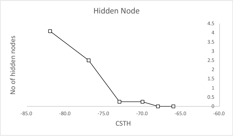
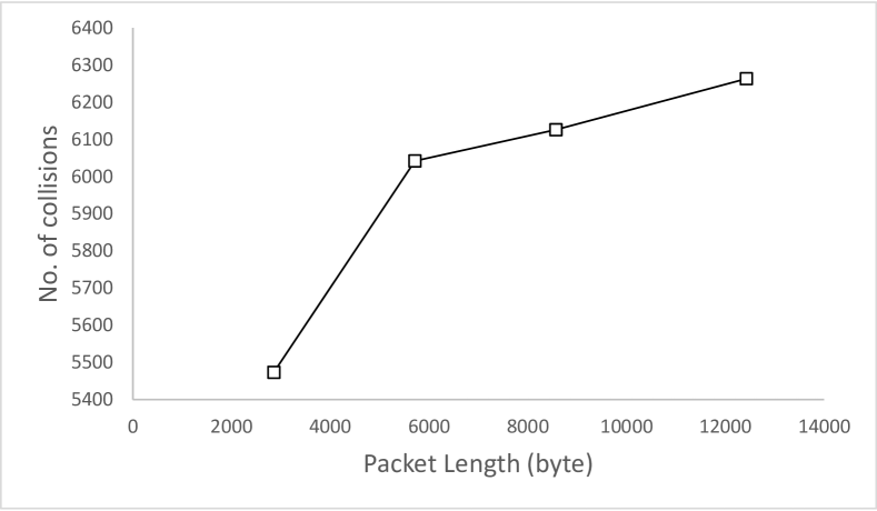
In the existing CSTH (-82dBm), each STA on an average sees four hidden terminals during transmission. With the increase of CSTH from -82 dBm to -73dBm, the average number of hidden terminals seen by a node reduces to 0.25 as shown in Fig. 23. Fig. 23 shows the number of collisions as a function of packet size. As the packet size decreases, the transmission time required by each packet decreases. As a result, nodes get frequent transmission opportunities and the collision probability decreases. However, this reduction is not significant because data packets do not suffer collision because, as soon as AP transmits CTS, the NAV of all other STAs are updated which eliminates hidden node problem for data packets.
5 Conclusion
We discussed the impact of hidden node problem in uplink transmission in a heterogeneous network. The simulation result showed significant throughput degradation due to the presence of hidden nodes in coexisting network. We strongly advocate in favour of increasing carrier sensing threshold of STAs by 10 dB during association with HE AP which not only increase network capacity but also reduce collision probability due to hidden node. We proposed some modification to the draft recommendation to reduce the inter BSS interference arising from asymmetrical transmission radius of AP and STAs.
6 Acknowledgments
Research presented here was in part supported through Canada’s National Science and Engineering Research Council (NSERC) Discovery Grants.
References
- [1] M. Z. Ali, J. Mišić, and V. B. Mišić. Impact of hidden nodes on uplink transmission in IEEE 802.11ax heterogeneous network. In Int. Wireless Communications and Mobile Computing Conf. (IWCMC), Limassol, Cyprus, June 2018.
- [2] M. Al-Bado, C. Sengul, C. J. Sreenan, and K. N. Brown. Hidden terminal management for uplink traffic in rate-controlled WiFi networks. In 2016 IEEE Symposium on Computers and Communication (ISCC), pages 1066–1071, June 2016.
- [3] E. Khorov, A. Kiryanov, and A. Lyakhov. Ieee 802.11ax: How to build high efficiency wlans. In 2015 International Conference on Engineering and Telecommunication (EnT), pages 14–19, Nov 2015.
- [4] A. k. Ajami and H. Artail. On the modeling and analysis of uplink and downlink ieee 802.11ax wi-fi with lte in unlicensed spectrum. IEEE Transactions on Wireless Communications, 16(9):5779–5795, Sept 2017.
- [5] M. Z. Ali, J. Mišić, and V. B. Mišić. Performance analysis of downlink MU-TXOP sharing in IEEE 802.11ac. IEEE Transactions on Vehicular Technology, PP(99):1–1, 2017.
- [6] M. Z. Ali, J. Mišić, and V. B. Mišić. Uplink Access Protocol in IEEE 802.11ac. IEEE Transactions on Wireless Communications, 17(8):5535–5551, Aug 2018.
- [7] S. I. Sou and Y. Lee. Trigger-based approach with hidden node problem for uplink multi-user transmission in 802.11ax. In 2017 IEEE 18th International Workshop on Signal Processing Advances in Wireless Communications (SPAWC), pages 1–5, July 2017.
- [8] Kiseon Ryu. Indication for UL MU carrier sensing. URL:https://mentor.ieee.org/802.11/dcn/16/11-16-0057-00-00ax-indication-for-ul-mu-carrier-sensing.pptx. 2016.
- [9] J. Misic, S. Rashwand, and V. B. Misic. Analysis of Impact of TXOP Allocation on IEEE 802.11e EDCA under Variable Network Load. IEEE Transactions on Parallel and Distributed Systems, 23(5):785–799, May 2012.
- [10] Wireless LANs: Proposed TGax draft specification. IEEE standard 802.11ax, The IEEE 802.11 Working Group of the 802 Committee, USA, March 2016.
- [11] J. Mvulla, E. C. Park, M. Adnan, and J. H. Son. Analysis of asymmetric hidden node problem in IEEE 802.11ax heterogeneous WLANs. In 2015 International Conference on Information and Communication Technology Convergence (ICTC), pages 539–544, Oct 2015.