(190.1450) Bistability; (350.3618) Left-handed materials; (190.7110); (160.3918) Metamaterials; (230.4320) Nonlinear optical devices.
Nonlinear anti-directional couplers with gain and loss
Abstract
Following the concept of -symmetric couplers, we propose a linearly coupled system of nonlinear waveguides, made of positive- and negative-index materials, which carry, respectively, gain and loss. We report novel bi- and multi-stability states pertaining to transmitted and reflective intensities, which are controlled by the ratio of the gain and loss coefficients, and phase mismatch between the waveguides. These states offer transmission regimes with extremely low threshold intensities for transitions between coexisting states, and very large amplification ratio between the input and output intensities leading to an efficient way of controlling light with light.
doi:
Optical systems with separated and globally balanced gain and loss, realizing the parity-time () symmetry [1, 2, 3, 4, 5], have drawn widespread interest in theoretical and experimental studies, as they exhibit rich phenomenology in the context of linear and nonlinear optics, see reviews [6, 7, 8, 9, 10, 11, 12] and references therein. In particular, directional couplers, alias dimers, which are composed of cores carrying equal amounts of gain and loss, serve as prime objects to explore the effects of -symmetry, in the continuous-wave (CW) [13, 14, 15, 16, 17] and soliton [18, 19] regimes. In the CW form, directional couplers (built without gain and loss) do not manifest any bistability, even when the Kerr nonlinearity is included [20] (although it may be made possible by additional ingredients, such as prism coupling in directional couplers [21] or saturable nonlinearity [22]).
Directional couplers with left-handed materials, which are supposed to add new dimensions to physics of light [23], including cloaking [24], magnetism at optical frequencies, reversed Snell’s law, reversed Goos-Hänchen shift, etc. [25, 26, 27], can exhibit novel nonlinear effects, such as optical bistability and gap solitons, the latter usually occurring in periodic structures [28, 29] and nonlinear Bragg gratings [30, 31, 32, 33]. In contrast to the conventional couplers, which are made of two positive-index material (PIM) waveguides, the metamaterial-including dual-core systems may be termed anti-directional couplers (ADCs), as the propagation dynamics in a negative-index-material (NIM) waveguide is opposite to that in conventional media. The latter fact is elucidated by the opposite direction of the Poynting vector ( in Fig. 1) in NIM, which leads to the opposite phase velocity and energy flow [34].
As is well known, NIMs are artificial materials which exhibit inherent loss due to the fact that their permittivity and permeability have imaginary parts [25]. This detrimental effect may render ADCs impractical as effective switching devices, even if experimental verification of their operation remains a relevant objective. Thus, an important issue is how the absorption in NIMs affects nonlinear dynamical effects in ADC and how one can compensate the loss, to make the device more useful for all-optical signal processing, including ultrafast switching and memory applications. Here we address this issue by introducing gain in the positive-index waveguide, as motivated by the above-mentioned studies of the -symmetric couplers. The settings with both equal and different values of the gain and loss in the two cores will be considered. As a result, we report new dynamical regimes provided by the so designed ADCs.
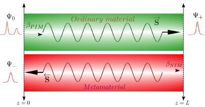
We start the analysis of the ADC model with intrinsic loss () and gain () in its NIM and PIM cores. Following Ref. [34] (where the gain and loss were not included), the corresponding coupled-mode equations representing the light propagation in the system are written as
| (1) | |||
| (2) |
where and are complex envelope amplitudes of the forward and backward waves in the PIM and NIM cores, respectively, is the propagation distance, and is the inter-core linear-coupling parameter. The phase-mismatch parameter, , is defined by the PIM and NIM propagation constants, , and Kerr terms in the two cores are represented by coefficients and .
Coupled-mode equations (1) and (2) were simulated using an implicit finite-difference method [35] with boundary conditions and . The objective was to produce the transmissivity () and reflectivity () defined as and , where is the incident intensity of light, coupled at into the PIM core, and is the ADC’s length, see Fig. 1.
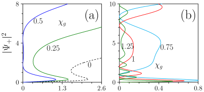
First, in Fig. 2 we present the results for the output intensity in the PIM core vs. the input value, for the PIM-NIM coupler with equal gain coefficients in both curves . Compared to the optical bistability found at (in the conservative system considered in Ref. [34]), the bistability takes a more pronounced shape, along with a substantial reduction in the switch-up and switch-down threshold, even when the gain-loss coefficient takes a relatively small value, . This behavior, different from usual hysteresis loops, in which one normally finds more pronounced bistable response along with a larger switch-up threshold intensity [36], persists up to , where the switching characteristic features a nearly flat vertical segment. Such a novel variety of the optical bistability may find applications to the design of ultra-fast switching and optical memory, as well as signal regenerators. There is a critical value, , above which the system gives rise to new forms of multistability, along with a dramatic drop in the lowest critical value of the intensity. When the gain-loss factor is raised to , the switch-up threshold starts to decrease by transforming the flat segment into a sharp one. Very small threshold intensities may be an obviously beneficial factor for applications.
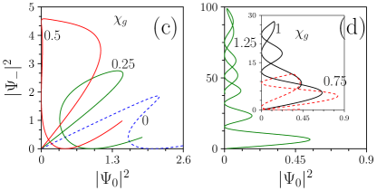
We have also discovered a new shape of the hysteresis curve for the reflected intensity, as shown in Fig. 2(c) and 2(d). It is worth to mention that previous studies on the conventional ADCs have never addressed bistability in reflection [34, 41]. Our results predict, on the contrary to the conventional setting (cf. the blue dashed hysteresis curve), such a novel reflection bistability, wherein one observes the formation of a loop, pertaining to an unstable segment on the hysteresis curve, when the value of equal gain is increased to . Although the intensity of the reflected wave increases, it is low compared to the transmitted intensity [cf. Fig. 2(a)], despite the fact that the size of the loop (the unstable domain) gets bigger. Remarkable ramifications are also noticed when the equal gain is set to . In particular, one can observe a new form of multistability, transforming from the looped shape to a novel one, similar to the multistability of the transmitted intensity. Actually, the amplitude of this novel multistability is much higher ( by a factor of ) than of the multistability of the transmitted intensity. Above a certain critical value, the development of the multistability reverts back by forming multiple loops. Also, at , lasing behavior is noticed (not shown here). Note that, although a similar (not exactly the same) reflective bistability has been observed in semi-conductor amplifiers [45] and Fabry-Pérot etalons [46], reflection multistability has not been reported before for any feedback structures, including Bragg gratings. Such a unique form of the reflection bistability may play an essential role in the design all-optical memory applications, such as AND and NAND gates [46]. In addition, the reflection multistability, driven by equal pumping, may open a new avenue for all-optical signal processing, including memory and switching in lightwave communication systems.
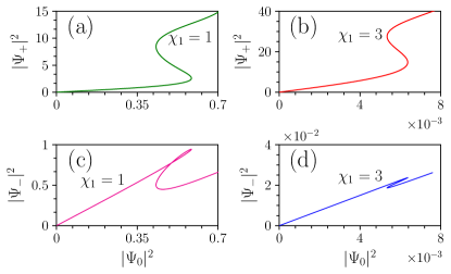
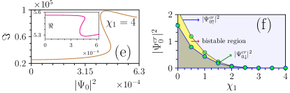
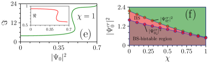
Figure 3 summarizes the most essential results of the present work, by analyzing the role of the balanced gain-loss parameter (). As was seen in Fig. 2 and is shown in Fig. 3, upon increasing up to , the threshold switch intensity reduces, while featuring huge amplification of the transmitted intensity in comparison to the nonlinear ADC without the gain and loss, cf. Ref. [34]. Though further increase of makes the amplification still larger, the hysteresis curve shrinks in the horizontal direction, gradually losing its bistability, which implies that the effective feedback is suppressed in the system as the value of increases, see Fig. 3(f). The role of the reflection bistability is displayed in Figs. 3(c) – 3(e), which demonstrate that the critical intensity for the switch-up bistability grows with the increase in the value of the equal-gain-loss parameter. Moreover, the width of the hysteresis curve and the amplitude of the reflected wave also get reduced, as in the case of the bistability corresponding to the transmitted intensity. Nonetheless, it is interesting to note that in both the types of bistabilities, the width of the hysteresis curve remains unchanged (i.e., the switch-up and down critical intensities of the reflection and transmission bistabilities remain the same).
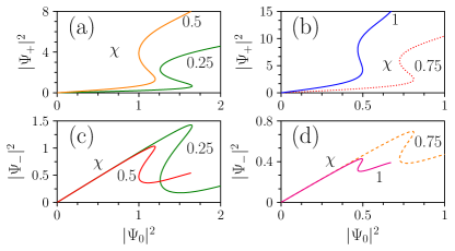
To expand the phenomenology, we now fix gain in the PIM arm to be twice the value of the loss parameter in the NIM channel, i.e., , plotting the respective results in Fig. 4. Unlike the previous case of , the bistability is efficiently sustained even at very high values of the gain and loss parameters (say, at ). In the present case, switching is possible at ultra-low incident intensity , whereas the transmissivity jumps to huge values, . Such results, which were not previously reported for nonlinear ADCs, may be beneficial in the context of all-optical signal processing [37]. Conversely, the reflective bistability delineated in Figs. 4(c)-4(e) exhibits another novel type of the hysteresis curve, with a loop different from the one observed in Fig. 3(c). Also, the first stable state resembles a ramp-like structure extended over a large range of the input intensity, while the unstable mode forms a loop. It is relevant to note too that, with the increase of the gain and loss coefficients, up to , in contrast to the transmission bistability, the intensity of the reflected wave is drastically reduced, following the transition of the hysteresis curve which loses its looped shape observed at lower values of the gain-loss parameter, cf. Fig. 4(c).
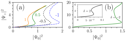
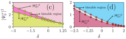
We have also studied the effects of the detuning parameter in Eqs. (1) and (2), , on the bistability, which was neglected in previous works [34, 41, 42, 43, 44], which solely addressed phase-matched ADC. Figure 5(a) displays how affects the input-output curves in the system with equal gain and loss, . It is seen that the increase of [for , one can refer to the solid orange bistability curve in Fig. 3(a)] tends to suppress the bistability and hysteresis. On the contrary, helps to expand the hysteresis area, shifting it, as whole, to larger values of the input intensity.
In addition, Fig. 5(b) shows that and produce qualitatively similar effects in the system with : comparing to the case of zero mismatch [Fig. 4(a)], the negative mismatch shifts the hysteresis to higher values of the incident intensity, while makes it possible to realize the switching at a very low intensity, while keeping substantial amplification of the transmitted power. The spectral range of the bistability for the two types of gain-loss systems is shown in Figs. 5(c) and 5(d). In the plot pertaining to equal amount of the gain and loss [Fig. 5(c)], one observes that the spectral range broadens, in addition to an increase in the switching (critical) intensities. An opposite situation is observed for the system in which the gain is twice as strong as loss, as seen in Fig. 5(d), where the width of the hysteresis curve (the bistable region) gets reduced for low switching intensities.
We have also analyzed the role of the ADC’s length, concluding that, quite naturally, low values of suppresses the hysteresis width, and the bistability tends to disappear, in short couplers. Conversely, an increase of the length helps to expand the hysteresis, in addition to reducing the switching threshold (not shown here in detail). Thus, one should select an optimum coupler length to design optical bistability with desirable properties.
To summarize, we have reported the role of gain and loss in the operation of the nonlinear ADC (anti-directional coupler). We have demonstrated that the gain and loss acting in the positive- and negative-index arms of the coupler give rise to novel bi- and multi-stability states, admitting dramatic reduction of the threshold intensity needed for transitions between these states. These effects can be efficiently controlled by means of the ratio of the gain and loss coefficients in the two arms, as well as by the phase mismatch between them.
Funding. Science and Engineering Research Board (SERB) of India: Grants Nos. PDF/2016/002933 and SB/DF/04/2017.
References
- [1] C. M. Bender and S. Boettcher, Phys. Rev. Lett. 80, 5243-5246 (1998).
- [2] P. Dorey, C. Dunning, and R. Tateo, J. Phys. A: Math. Gen. 34, 5679-5704 (2001).
- [3] C. M. Bender, D. C. Brody, and H. F. Jones, Phys. Rev. Lett. 89, 270401 (2002).
- [4] A. Ruschhaupt, F. Delgado, and J. G. Muga, J. Phys. A: Math. Gen. 38, L171-L176 (2005).
- [5] R. El-Ganainy, K. G. Makris, D. N. Christodoulides, and Z. H. Musslimani, Opt. Lett. 32, 2632-2634 (2007).
- [6] C. M. Bender, Rep. Prog. Phys. 70, 947-1018 (2007).
- [7] K. G. Makris, R. El-Ganainy, D. N. Christodoulides, and Z. H. Musslimani, Int. J. Theor. Phys. 50, 1019-1041 (2011).
- [8] N. Moiseyev, Non-Hermitian Quantum Mechanics, (Cambridge University Press, 2011).
- [9] V. V. Konotop, J. Yang, and D. A. Zezyulin, Rev. Mod. Phys. 88, 035002 (2016).
- [10] S. V. Suchkov, A. A. Sukhorukov, J. H. Huang, S. V. Dmitriev, C. Lee, and Y. S. Kivshar, Laser Photonics Rev. 10, 177-213 (2016).
- [11] R. El-Ganainy, K. G. Makris, M. Khajavikhan, Z. H. Musslimani, S. Rotter, and D. N. Christodoulides, Nature Phys. 14, 11 (2018).
- [12] B. A. Malomed, Vortex solitons: Old results and new perspectives, Physica D, in press; https://doi.org/10.1016/j.physd.2019.04.009.
- [13] C. E. Rüter, K. G. Makris, R. El-Ganainy, D. N. Christodoulides, M. Segev, and D. Kip, Nat. Phys. 6, 192 (2010).
- [14] J. Cuevas, P. G. Kevrekidis, A. Saxena, and A. Khare, Phys. Rev. A 88, 032108 (2013).
- [15] I. V. Barashenkov, Phys. Rev. A 90, 045802 (2014).
- [16] J. D. Huerta Morales, B. M. Rodrígues-Lara, and B. A. Malomed, Opt. Lett. 42, 4402-4405 (2017).
- [17] A. Govindarajan, A. K. Sarma, and M. Lakshmanan, Opt. Lett. 44, 663 (2019).
- [18] R. Driben and B. A. Malomed, Opt. Lett. 36, 4323-4325 (2011).
- [19] N. V. Alexeeva, I. V. Barashenkov, A. A. Sukhorukov, and Y. S. Kivshar, Phys. Rev. A 85, 063837 (2012).
- [20] S. Jensen, IEEE J. Quantum Electron. 18, 1580 (1982).
- [21] G. Stegeman, G. Assanto, R. Zanoni, C. Seaton, E. Garmire, A. Maradudin, R. Reinisch, and G. Vitrant, Appl. Phys. Lett. 52, 869 (1988).
- [22] A. W. Snyder, D. J. Mitchell, L. Poladian, D. R. Rowland, and Y. Chen, J. Opt. Soc. Am. B 8, 2102-2118 (1991).
- [23] N. M. Litchinitser, Science 337, 1054 (2012).
- [24] D. Schurig, J. Mock, B. Justice, S. A. Cummer, J. B. Pendry, A. Starr, and D. Smith, Science 314, 977 (2006).
- [25] N. Engheta and R. W. Ziolkowski, Metamaterials: physics and engineering explorations (John Wiley & Sons 2006).
- [26] A. I. Maimistov and I. R. Gabitov, Eur. Phys. J-Spec. Top. 147, 265 (2007).
- [27] M. Lapine, I. V. Shadrivov, and Y. S. Kivshar, Rev. Mod. Phys. 86, 1093 (2014).
- [28] H. G. Winful, J. Marburger, and E. Garmire, Appl. Phys. Lett. 35, 379 (1979).
- [29] E. A. Cerda-Méndez, D. Sarkar, D. N. Krizhanovskii, S. S. Gavrilov, K. Biermann, M. S. Skolnick, and P. V. Santos, Phys. Rev. Lett. 111, 146401 (2013).
- [30] A. B. Aceves and S. Wabnitz, Phys. Lett. A 141, 37-42 (1989).
- [31] D. N. Christodoulides and R. I. Joseph, Phys. Rev. Lett. 62, 1746-1748 (1989).
- [32] C. M. de Sterke and J. E. Sipe, Progr. Optics 33, 203-260 (1994).
- [33] B. J. Eggleton, R. E. Slusher, C. M. de Sterke, P. A. Krug, and J. E. Sipe, Phys. Rev. Lett. 76, 1627-1630 (1996).
- [34] N. M. Litchinitser, I. R. Gabitov, and A. I. Maimistov, Phys. Rev. Lett. 99, 113902 (2007).
- [35] R. J. LeVeque, Finite difference methods for ordinary and partial differential equations: steady-state and time-dependent problems, volume 98 (SIAM 2007).
- [36] G. Iooss and D. D. Joseph, Elementary Stability and Bifurcation Theory (Springer: Berlin, 1980).
- [37] S. Radic, N. George, and G. P. Agrawal, Opt. Lett. 19, 1789 (1994).
- [38] W. Chen and D. Mills, Phys. Rev. Lett. 58, 160 (1987).
- [39] H. G. Winful, R. Zamir, and S. Feldman, Appl. Phys. Lett. 58, 1001 (1991).
- [40] G. D’Aguanno, N. Mattiucci, M. Scalora, and M. J. Bloemer, Phys. Rev. Lett. 93, 213902 (2004).
- [41] G. Venugopal, Z. Kudyshev, and N. M. Litchinitser, IEEE J. Sel. Top. Quantum Electron. 18, 753 (2012).
- [42] A. Maimistov and E. Kazantseva, Optics and Spectroscopy 112, 264 (2012).
- [43] E. Kazantseva and A. Maimistov, Optics and Spectroscopy 119, 776 (2015).
- [44] K. Nithyanandan, A. S. Ali, K. Porsezian, M. Nishad, P. T. Dinda, and P. Grelu, Opt. Commun. 416, 145 (2018).
- [45] D. N. Maywar and G. P. Agrawal, IEEE J. Quantum Electron. 34, 2364 (1998).
- [46] M. J. Adams, Opt. Quant. Electron. 19, S37 (1987).