An Optimal Assistive Control Strategy
based on User’s Motor Goal Estimation
Abstract
In this study, we propose an optimal assistive control strategy that uses estimated user’s movement intention as the terminal cost function. We estimate the movement intention by observing human user’s joint angle, angluar velocity, and muscle activities for very short period of time. A task-related low-dimensional feature space is extracted from the observed user’s movement data. We assume that discrete number of optimal control laws associated to different target tasks are pre-computed. Then, the optimal assistive policy is derived by blending the pre-computed optimal control laws based on the linear Bellman combination method. Coefficients that determine how to blend the control laws are derived based on the low-dimensional feature value that represents the user’s movement intention. To validate our proposed method, we conducted basketball throwing tasks. In these experiments, subjects were asked to throw a basketball into a hoop placed at different throwing distances. The distances from the throwing point to the hoop were estimated as the user’s movement intention and the optimal control policies were derived by using our proposed method. The results showed that the basketball throwing performances of the subjects were mostly improved.
I INTRODUCTION
Because of the recent progress in robotics technologies, wearable robots, such as exoskeleton robots, are expected to physically interact with and assist humans in their activities. As proof-of-principle, the hand exoskeleton [1, 2], and upper and lower-body exoskeleton robots [3, 4, 5] have been studied. For these applications, the use of surface electromyography (EMG) can be a possible approach to intuitively control the robots by estimating the user’s movement intention [6, 7].
Concretely, using linearly scaled electromyography (EMG) to derive joint torques of an assistive device is a standard approach for an exoskeleton robot control. However, to accomplish a given task based on this simple EMG-based control strategy, human users need to generate highly-tuned EMG profiles by themselves. Therefore, this standard approach can increase the computational burden of human users nervous system even though it may be able to reduce the physical burden. The other popular approach to estimate human movement intention is applying a classification method to estimate an associated movement to observed EMG signals. In this case, EMG is only used for initiating pre-designed movements. Therefore, from computational point of view, it seems suitable approach for assistive control. However, we can use this approach only for limited number of discrete target tasks since all the assitive controllers associated to the target tasks need to be pre-computed.
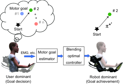
In this study, we develop an assistive control method that takes advantage of the above two standard approaches. In our proposed method, We estimate the movement intention by observing human user’s joint angle, angluar velocity, and muscle activities for very short period of time. A low-dimensional feature space that is related a given task is extracted from these observed data related to user’s movements. We assume that discrete number of optimal control laws associated to different tasks are pre-computed. Then, the optimal assistive policy is derived by blending the pre-computed optimal control laws based on the linear Bellman combination method. Coefficients that determine how to blend the control laws are derived by monitoring the low-dimensional feature value that represents the user’s movement intention (see Fig. 1). To validate our proposed method, we conducted basketball throwing tasks. In these experiments, subjects were asked to throw a basketball into a hoop placed at different throwing distances. The distances from the throwing point to the hoop were estimated as the user’s movement intention and the optimal control policies were derived by using our proposed method. The results showed that the basketball throwing performances of the subjects were mostly improved.
The rest of this paper is organized as follows. In Section II, we have introduced the related EMG-based control strategies for the exoskeleton robot. In Section III, we explain our user’s goal estimation-based optimal control approach. Section IV describes the experimental setups. Section V describes our experimental results. Finally, the conclusion is provided in Section VII.
II Related works
In order to intuitively control assisitive devices such as exoskeleton robots, regression approaches are often used to estimate the user’s movement intention. In these approaches, a motion intention was estimated by finding relationships between EMG signals and joint torques with linear or non-linear models [8, 9, 10]. In this method, the robot can be continuously controlled according to the monitored muscle activities. However, since the fixed relationships were used in these regression methods, human users need to carefully generate own EMG profiles to cope with variety of tasks.
Another frequently used approach to estimate user’s movement intention is using a classification method. For example, support vector machine (SVM) [11] or linear discriminant analysis (LDA) [12] were adopted to classify measured information detected from human users. The classification results were used to initiate pre-designed control output patterns associated to the estimated class labels.
In this study, we take the advantages of these two approaches. We first prepare pre-optimaized assistive control laws. Then these optimal control laws are combined using linear Bellman combination method[13] to generate continuous optimal control output for exoskeleton robot. Therefore, the human users do not need to carefully generate their own EMG signals since our method derives optimal policy for a given task estimated from the measured data caused by user’s movements. Furthermore, since we just combine the pre-optimized control laws to derive the corresponding optimal policy to the given task, the proposed approach is computationally light and can easily derive the policy in realtime.
III METHODS
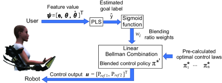
This section introduces our approach for determining the control policy to assist the user’s motor goal (see Fig. 2).
III-A User’s motor goal estimation
To cope with the continuous change of user’s motor goal, we first find low-dimensional feature space to determine how to combine the pre-optimized control outputs.
In this study, we used the partial least squares (PLS) algorithm [14, 15] to find the task related low-dimensional feature space. First, the user’s states associated with the goal labels were observed. Here we considered a dataset with samples as : , and . In PLS, for a given sample set, the direction of the -dimensional feature space is determined such that the sample covariance of and is maximized in the space of the feature as described below:
| (1) |
The projection from the original -dimensional feature space to a -dimensional space () can be performed as follows:
| (2) |
As described above, since the subspace is selected in consideration with the covariance with the class labels, the low-dimensional features reflecting the label information can be obtained. In this study, the user’s motor goal was estimated directly by the regression model between the low-dimensional feature and label . The estimated is used to determine the coefficients for the linear Bellman combination in (7). To map the as blending ratio weights between and , we use the sigmoid function as follows:
| (3) |
where, the and are the parameters adjusted according to experimental conditions.
III-B Optimal control based on motion intention
In this study, we considered deriving the control policy according to the user’s motor goal as follow:
where, indicates the optimal control policy for achieving the target goal, indicates the state variable, and reflects the user’s motor goal. The purpose here is to find the optimal policy that achieves the user’s motor goal. A simple method is to set an objective function corresponding to the user’s target goal and optimize it. However, creating a controller that achieves the target usually needs either time-consuming manual tuning dependent on experience or cost-intensive computational burden for the optimization. In addition, it is difficult to create a controller corresponding to each target if the targets change continuously. Therefore, presently, we considered reusing the optimal controllers which were obtained for the new target by combining them as follows:
| (4) |
where, is the mixing coefficient, and indicates the sub-optimal control policy for the component of the motor goal task obtained by minimizing the total cost (or objective function) as follows:
| (5) |
| (6) |
where, and indicate the terminal cost and instantaneous cost, respectively.
Assuming the availability of a collection of finite horizon control problems that share all setting except the terminal cost of (5), the linear bellman combination approach [13], [16] can be used, and the can be written as follows:
| (7) |
where, , indicates the feasibility of the policy for the current state, and is the fixed weights to determine the goal of the controller.
In order to derive each of the sub-optimal policies , we used the iterative linear-quadratic-regulator (iLQR) method as the optimal control [17] for non-linear system dynamics described as follows:
| (8) |
where, indicates the state and is the input. The problem with optimization is to find the optimal control policy that minimizes the objective function (5). The control policy is calculated as follows:
| (9) |
where, is the sampling number and is the sampling time. Each iteration of the iLQR algorithm begins with a nominal control sequence and the corresponding trajectory , and is observed by applying to the dynamics equation (8) with . The iLQR method solves the optimization problem for non-linear system by linearizing the system dynamics and with second-order approximation of the objective functions around a nominal control sequence and the corresponding nominal trajectory . Therefore, the iLQR problem is solved using the Riccati-like equations [17] and the control law is
| (10) |
where, , and is an open loop term and is the feedback term ( see [17] for further details).
IV Experimental setups
To validate our approach, we conducted experiments with three healthy right handed subjects, after obtaining informed consent from them.
IV-A Upper limb exoskeleton robot
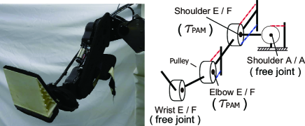
In our robot experiment, the optimal policies were derived to control two joints of the upper limb of the exoskeleton robot (see, Fig.3): shoulder flexion/extension (SFE), elbow flexion/extension(EFE) joints. Each joint is actuated by pneumatic artificial muscle (PAM). As depicted in Fig.3, the robot has the remaining two degrees of freedom; shoulder abduction/adduction (SAA) and wrist flexion/adduction (SAA) joints, but in this experiment they were set as free joints. The joint torques are generated by a PAM as follows:
| (11) |
where, is the pulley radius and is the PAM force generated by the path contraction of the spiral fibers embedded in a pneumatic bladder. The details of the mechanical design and the pressure-force model were introduced in our previous studies [18, 19, 9].
In this study, we considered the dynamics of the two-link robot model. When deriving the control policy to assist the user’s motion, we considered the dynamics as a system of human and robot as follows: the user’s link weights where the center of the link mass (calculated from the subject’s body parameter [20]) were added to the robot link weights. The state variable included the joint angle , angular velocity , and measured inner pressure of PAM for the dynamics eq.(8): . where, the subscripts and at the lower right represent the shoulder and elbow joint, respectively. The control outputs were the desired pressure inputs for pneumatic actuators : . Although the dynamics between the reference pressure and the measured inner pressure has non-linearity due to the air dynamics, we can approximate the dynamics by the first order lag system [18] as follows:
| (12) |
where, is the time constant and is set as follows:
In addition, the maximum pressure is set to MPa for safety.
The terminal cost for minimization was set as follows:
| (13) |
where, is the final time, is the target angles, and is the target angular velocities at the point of release of the ball for the basketball throwing task and was calculated according to goal distance.
The instantaneous cost was set as
| (14) |
where, were manually selected as in the most of optimal control studies.
IV-B Motion Task
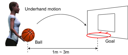
To evaluate our proposed approach, we set the basketball goal shoot as the concrete motion task as depicted in Fig. 4. In this task, the subjects threw a basketball with underhand motion in the sitting condition, and the distance of the hoop was changed to 1 m, 2 m, and 3 m. The subjects were instructed to throw the ball only with their arms and were asked to throw the ball under two conditions; wearing the exoskeleton robot but No-Assist (NA), wearing the exoskeleton robot with Assist (A). The subjects threw the ball ten times in each condition. To measure the timing of the release of the ball, one tactile sensor was attached to the tip of the subject’s middle finger.
IV-C Feature selection and parameter identification based on PLS
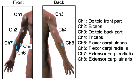
In order to estimate the user’s motor goal from a slight, initial motion, the rectified and filtered EMG signals: , angles of the shoulder and elbow joint, and angular velocities generated by the shoulder and elbow joint are used as the features: (totally -dimension). The EMG signals were measured from the right arms of the subjects. Figure 5 shows the EMG locations probed to measure the muscle activities using sensor channels (Ch1: , Ch2: , Ch3: , Ch4: , Ch5: , Ch6: , Ch7: , Ch8: ). We used Ag/AgCl bipolar surface EMG electrodes. Using the encoder of the upper-limb exoskeleton robot system, we simultaneously obtained both the angles and angular velocities of the shoulder and elbow joint.
During the basketball goal shooting motion, the point at which the angular velocity of the shoulder joint exceeds the threshold is defined as the motion start point. This is because we observed the tendency of the shoulder joint to move earlier than the elbow in this task, from the preliminary experiment. Moreover, the threshold was set to from the preliminary experiment. The average value of each data tens of milliseconds before the motion start point is used as the feature value . In particular, the EMG signals are activated ms prior to the actual limb movements [21], and this latency is set by the cross validation of the training-data.
In this study, the sensor values were acquired as the training data when the exoskeleton robot assisted the motion for shooting the goal at a distance of 1 m and 3 m, assuming that the goal is known. With the corresponding labes and (: 1 m throw, : 3 m throw), a projection matrix for calculating the one-dimensional feature by PLS was derived.
V RESULTS
In this section, we first show the simulation results, and subsequently, the results of the online assist control based on the user’s motor goal estimation.
V-A Simulation results
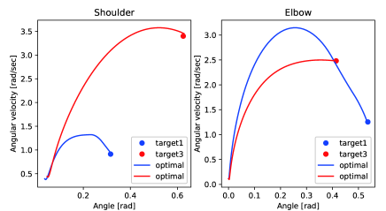
Figure 6 shows the simulation results of the state transition generated by the optimal control policies. Error between the target and generated angles and angular velocities at the release point in final time were as follows: Shoulder joint angle is rad, angular velocity is rad/s, elbow joint angle is rad, angular velocity is rad/s in the 1 m ball throw condition, whereas, in the 3 m ball throw condition, the shoulder joint angle is rad, angular velocity is rad/s, elbow joint angle is rad, and angular velocity is rad/s. Similar results were obtained for dynamics in other users, and moreover, the errors were small. From these results, we could get the optimal control policy to realize the target state which is necessary for the release point of the basketball.
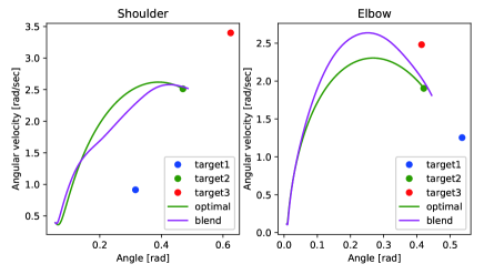
Figure 7 shows the state transition results from the blending method of the optimal control policy for 2 m goal shot. To calculate the blended control policy for the 2 m goal shot condition, the weight parameters were set as and , where, the and represents the weights for blending the optimal control policy of the 1 m and 3 m goal shot conditions, respectively. For comparison, the state transition result by optimal control policy for the 2 m goal shot condition is also shown. Error between the target and generated angles of release point in final time were as follows: shoulder joint angle, rad; angular velocity, rad/s; elbow joint angle, rad and angular velocity, rad/s, with optimal control policy, and shoulder joint angle, rad; angular velocity, rad/s; elbow joint angle, rad, and angular velocity, rad/s, with the blended control policy. The final state was close to the target. The result indicates the usefulness of the blended policy for the new goal shot condition.
V-B Feature extraction and weight determination based on PLS
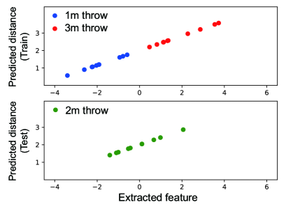
We validated the tendency of the PLS results. Figure 8 shows the representative tendency of the feature values of one subject obtained by PLS and the corresponding user’s motor goals. The parameters for PLS were trained by using the 1 m and 3 m goal shot data, and tested with the 2 m goal shot data. This figure indicates that the feature values and goal labels have order according to the distance condition. This tendency was seen in other subjects as well. Therefore, it was shown that the estimated goal label can be used as a user’s motor goal calculated by (3). In this study, based on these results, we set the user’s motor goal for the 1 m goal shot as and the 3 m goal shot as . If the user intends to throw at a distance of 1 m, the weight is high and the is small. Conversely, if the user intends to throw at a distance of 3 m, the weight decrease and the increases.
V-C Online control results of basketball goal shoot
In this subsection, we describe the experimental results of the basketball goal shooting test with our proposed assist control approach.
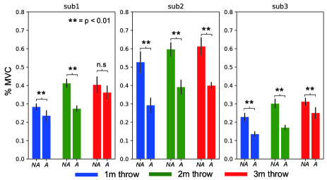
To verify the effect of the assist, we observed the amplitudes of the rectified and filtered EMG signals. Figure. 9 shows the average and standard deviation MVC (Maximum Voluntary Contraction) of all EMG signals generated during the 10 times the ball was thrown. The MVC was the normalized muscle activity for each muscle separately, by using the maximum value of the rectified and low-pass filtered EMG signal: MVC = . We applied the Welch’s -test between the MVC of NA and A conditions. Among most of the subjects, we found that the average MVCs significantly decreased under condition A as compared to condition NA. Although the 3 m distance goal shot with condition A in subject 1 did not show a significant difference, it can be confirmed that the average MVCs tended to decrease compared to condition NA. These results show that the control policies derived by our proposed approach successfully assist the user’s ball throwing motions.
| sub1 | ||
| NA | A | |
| 1m throw | % | % |
| 2m throw | % | % |
| 3m throw | % | % |
| sub2 | ||
| NA | A | |
| 1m throw | % | % |
| 2m throw | % | % |
| 3m throw | % | % |
| sub3 | ||
| NA | A | |
| 1m throw | % | % |
| 2m throw | % | % |
| 3m throw | % | % |
Table I shows the goal shoot rate when throwing the ball ten times in each of the conditions, by each subject. When throwing the ball at a distance of 1 m, the shoot rate under the NA and A conditions did not change much for all subjects, And therefore, It was considered that the goal distance was close and easy task. However, it was observed that the assist control did not disturb the ball throwing motion. This was the result of correct estimation of the user’s motor goal. At a goal distance of 2 m, the subjects 2 and 3 had higher shoot rate as compared to the NA condition. This indicates that the goal shoot can be made with high accuracy and less effort in condition A as compared to the NA condition. On the contrary, in the subject 1, although the user’s motor goal was accurately estimated, the shoot accuracy was lower in condition A than in NA condition. This might be because the 2 m goal shoot distance would have been an easy task for this user. Therefore, although the exoskeleton robotic assistance reduced the effort of the motion, it may not have affected the goal shoot accuracy. At a goal distance of 3 m, the subjects 1 and 3 demonstrated that the shoot rate under condition A is higher compared to that in condition NA with lower effort. With respect to subject 2, the shoot rate remained at even under condition A, and this goal distance task seems to be quite difficult even though the robot assisted the motion.
From these results, it was shown that our proposed approach is effective in assisting the control for motion that requires speed and accuracy.
To further evaluate the shoot rate with our proposed approach, it can be beneficial to explicitly take the control of other joints, e.g., shoulder abduction/adduction, wrist joint, into account. In addition, in this research, the relationship between the feature values and user’s motor goals is ordered, extending our method to cope with the tasks where the relationship is complicated would be one of the interesting directions as a part of future study.
VI CONCLUSIONS
Our findings indicated that the proposed approach for controlling the assistive exoskeleton robot was successful in the simulated and actual basketball shooting experiments. The effort required to throw the ball was lower under the assisted condition than under the other conditions, with accuracy increasing as task difficulty increased in most participants. These results demonstrate that our proposed approach effectively allows for robot-assisted control of motions requiring speed and accuracy.
In this study, control policies were blended using a linear Bellman combination approach. That is, control policies for the 2-m condition were derived based on the optimal control policies for the 1-m and 3-m conditions. Our findings suggest that this approach can be used for the coordination of new tasks [13], although further studies are required to examine this hypothesis. Future studies should also consider extending this approach to handle a variety of motions that require greater degrees of freedom.
ACKNOWLEDGMENT
This work was supported by JST, ACT-i, Grant Number JPMJPR18UQ, Japan. The results presented have been achieved by ”Research and development of technology for enhancing functional recovery of elderly and disabled people based on non-invasive brain imaging and robotic devices,” the commissioned research of the National Institute of Information and Communications Technology (NICT), JAPAN. Part of this research was supported by JSPS KAKENHI Grant Number JP18K18135.
References
- [1] J. Ngeo, T. Tamei, T. Shibata, M. Orlando, L. Behera, A. Saxena, and A. Dutta, “Control of an optimal finger exoskeleton based on continuous joint angle estimation from emg signals,” pp. 338–341, July 2013.
- [2] C. J. Gearhart, B. Varone, M. H. Stella, and B. F. BuSha, “An effective 3-fingered augmenting exoskeleton for the human hand,” in 2016 38th Annual International Conference of the IEEE Engineering in Medicine and Biology Society (EMBC), Aug 2016, pp. 590–593.
- [3] J. Furukawa, T. Noda, T. Teramae, and J. Morimoto, “Estimating joint movements from observed emg signals with multiple electrodes under sensor failure situations toward safe assistive robot control,” in IEEE International Conference on Robotics and Automation (ICRA), May 2015, pp. 4985–4991.
- [4] A. J. Young and D. P. Ferris, “State of the art and future directions for lower limb robotic exoskeletons,” IEEE Transactions on Neural Systems and Rehabilitation Engineering, vol. 25, no. 2, pp. 171–182, Feb 2017.
- [5] K. Gui, H. Liu, and D. Zhang, “A generalized framework to achieve coordinated admittance control for multi-joint lower limb robotic exoskeleton,” in 2017 International Conference on Rehabilitation Robotics (ICORR), July 2017, pp. 228–233.
- [6] K. Nagata and K. Magatani, “Basic study on combined motion estimation using multichannel surface emg signals,” 33rd Annual International Conference of the IEEE EMBS Boston, Massachusetts USA, August 30 - September 3, pp. 7865–7868, 2011.
- [7] P. K. artemiads and K. J. Kyriakopoulos, “An emg-based robot control scheme robust to time-varying emg signal features,” IEEE TRANSACTION ON INFORMATION TECHNOLOGY IN BIOMEDICAL, vol. 14, no. 3, pp. 582–588, 2010.
- [8] D. Ao, R. Song, and J. Gao, “Movement performance of human robot cooperation control based on emg-driven hill-type and proportional models for an ankle power-assist exoskeleton robot,” IEEE Transactions on Neural Systems and Rehabilitation Engineering, vol. 25, no. 8, pp. 1125–1134, Aug 2017.
- [9] J. Furukawa, T. Noda, T. Teramae, and J. Morimoto, “Human movement modeling to detect biosignal sensor failures for myoelectric assistive robot control,” IEEE Transactions on Robotics, vol. PP, no. 99, pp. 1–12, 2017.
- [10] C. Fleischer and G. Hommel, “A human-exoskeleton interface utilizing electromyograpy,” IEEE TRANSACTION ON ROBOTICS, vol. 24, no. 4, pp. 872–882, 2008.
- [11] M. A. Oskoei∗ and H. Hu, “Support vector machine-based classification scheme for myoelectric control applied to upper limb,” IEEE Transactions on Biomedical Engineering, vol. 55, no. 8, pp. 1956–1965, Aug 2008.
- [12] D. Zhang, X. Zhao, J. Han, and Y. Zhao, “A comparative study on pca and lda based emg pattern recognition for anthropomorphic robotic hand,” in 2014 IEEE International Conference on Robotics and Automation (ICRA), May 2014, pp. 4850–4855.
- [13] M. da Silva, F. Durand, and J. Popovic, “Linear bellman combination for control of character animation,” 2009, pp. 82:1–82:10.
- [14] H. Wold, “Soft modeling by latent variables: the nonlinear iterative partial least squares approach,” in Perspective in Probability and Statistics, Paper in Honour of M. S. Bartlett, pp. 520–540, 1975.
- [15] S. Wold, M. Sjostrom, and L. Eriksson, “Pls-regression: a basic tool of chemometrics,” Chemometrics and Intelligent Laboratory Systems, vol. 2, pp. 109–130, 2001.
- [16] E. Todorov, “Compositionality of optimal control laws,” 2009, pp. 1856–1864.
- [17] E. Todorov, C. Hu, A. Simpkins, and J. Movellan, “A generalized iterative lqg method for locally-optimal feedback control of constrained nonlinear stochastic systems,” 2005, pp. 300–306.
- [18] T. Teramae, T. Noda, and J. Morimoto, “Optimal control approach for pneumatic artificial muscle with using pressure-force conversion model,” in 2014 IEEE International Conference on Robotics and Automation (ICRA), May 2014, pp. 4792–4797.
- [19] T. Noda, T. Teramae, B. Ugurlu, and J. Morimoto, “Development of an upper limb exoskeleton powered via pneumatic electric hybrid actuators with bowden cable,” in Intelligent Robots and Systems (IROS 2014), 2014 IEEE/RSJ International Conference on, Sept 2014, pp. 3573–3578.
- [20] D. A. Winter, Biomechanics and motor control of human movement. John Wiley & Sons, Inc, 2009.
- [21] Y. Koike and M. Kawato, “Estimation of dynamic joint torques and trajectory formation from surface electromyography signals using a neural network model,” Biological Cybernetics, vol. 73, no. 4, pp. 291–300, Sep 1995.