Enantio-discrimination via light deflection effect
Abstract
We propose a theoretical method for enantio-discrimination based on the light deflection effect in four-level models of chiral molecules. This four-level model consists of a cyclic three-level subsystem coupled by three strong driving fields and an auxiliary level connected to the cyclic three-level subsystem by a weak probe field. It is shown that the induced refractive index for the weak probe field is chirality-dependent. Thus it will lead to chirality-dependent light deflection when the intensities of two of the three strong driving fields are spatially inhomogeneous. As a result, the deflection angle of the weak probe light can be utilized to detect the chirality of pure enantiomers and enantiomeric excess of chiral mixture. Therefore, our method may act as a tool for enantio-discrimination.
pacs:
11.30.Rd, 33.80.-b, 42.50.-pI Introduction
In nature, one of the most important manifestations of symmetry breaking is the separated existence of two molecular structural forms known as enantiomers (e.g., and enantiomers) which are mirror images of each other MolecularStructure . Molecular chirality has received considerable interest due to its fundamental role in the activity of various biological molecules and chemical reactions EnantioEffect-Science1991 ; EnantioEffect-Nature1997 . Despite this importance, detecting the chirality of pure enantiomer (containing only or enantiomers) and enantiomeric excess of chiral mixture (containing both and enantiomers) remains an important and challenging task Challenge-CD ; Challenge-VCD ; Challenge-ROA ; challenge-Nature1998 ; challenge-Nature2000 ; Challenge-Science2002 ; Challenge-JSepSci2007 .
The optical rotation, which refers to the rotation of the polarization plane of a linearly polarized light in a medium of chiral molecules, is one of the conventional spectroscopic methods for enantio-discrimination (detecting the chirality of pure enantiomers and enantiomeric excess of chiral mixture) OR-Science1998 ; OR-Chirality2003 ; 2013WeakMeasOR ; 2016WeakMeasOR+CCD ; 2018WeakMeasOR . The optical rotation arises from the fact that the opposite enantiomers (e.g., or enantiomers) can lead to different refractive index for left- and right-circularly polarized lights Barron-MolecularScatter . Inspired by this, the reflection, refraction, and diffraction effects of left- and right-circularly polarized lights have been proposed to detect the chirality of pure enantiomers and enantiomeric excess of chiral mixture in experiments ChiralReflectRefract ; ChiralDiffract ; Enhanced-ChiralRefract . Nevertheless, the chiral effects in most of these methods are based on the interference between the electric- and magnetic-dipole transitions and thus are weak since the magnetic-dipole transition moment is usually weak.
Recently, the cyclic three-level (-type) model LiuYuXi-SQClooplevel ; YeChong-RealLoop of chiral molecules based on electric-dipole transitions has received much interest and has been widely used in enantio-separation LY-2007SeparationLoop ; LY-2008SeparationLoop ; Shapiro-2010SeparationLoop ; JiaWZ-2010SeparationLoop ; Vitanov-2019SeparationLoop ; WuJL-2019SeparationLoop and enantio-discrimination JiaWZ-2011DiscriminationLoop ; Hirota-2012DiscriminationLoop ; Doyle-2013DiscriminationLoop ; Doyle-2013ChiralTWMLoop ; Doyle-2014ChiralTWMLoop ; Lehmann-2015DiscriminationLoop ; Schnell-2014DiscriminationLoop ; Schnell-2015DiscriminationLoop ; Lehmann-2017DiscriminationLoop . In such a model, the product of three Rabi frequencies in the cyclic three-level model can change sign with enantiomer, thus it will lead to chirality-dependent dynamic processes LY-2008SeparationLoop ; Vitanov-2019SeparationLoop ; Hirota-2012DiscriminationLoop ; Doyle-2013DiscriminationLoop ; Doyle-2013ChiralTWMLoop ; Doyle-2014ChiralTWMLoop ; Lehmann-2015DiscriminationLoop ; Schnell-2014DiscriminationLoop ; Schnell-2015DiscriminationLoop ; Lehmann-2017DiscriminationLoop ; Doyle-2017decoherenceValue and steady-state optical responses JiaWZ-2011DiscriminationLoop .
In this paper, we propose a theoretical method for enantio-discrimination based on the light deflection effect in four-level models of chiral molecules. This four-level model consists of a cyclic three-level subsystem coupled by three strong driving fields and an auxiliary level which is connected to the cyclic three-level subsystem by a weak probe field. Here, two of the three strong driving fields are spatially inhomogeneous in order to produce spatially inhomogeneous refractive index for the weak probe light. Since the product of three Rabi frequencies corresponding to the cyclic three-level subsystem can change sign with enantiomer, the resultant refractive index leads to chirality-dependent propagation trajectory of the weak probe light which propagates in a medium of pure enantiomers. Therefore, the chirality of pure enantiomers can be detected by monitoring the deflection angle of the weak probe light when it exits from the medium. Further, we demonstrate that such a chirality-dependent deflection angle can also be utilized to detect the enantiomeric excess of chiral mixture. Moreover, the tunability of the amplitude of the deflection angle and robustness of the measurement precision against the Rabi frequency corresponding to the homogeneous driving field and enantiomeric excess are also investigated.
Here, we remark that the principle of our method is to measure the deflection angle of a probe light when it exits from the medium of enantiomers, which is very different from that of most optical rotation based methods OR-Science1998 ; OR-Chirality2003 ; Barron-MolecularScatter ; ChiralReflectRefract ; ChiralDiffract ; Enhanced-ChiralRefract ; 2013WeakMeasOR ; 2016WeakMeasOR+CCD ; 2018WeakMeasOR . Moreover, our method involves only the electric-dipole transitions and thus can produce desirable chirality-dependent deflection angle. Hence, our method may have wide applications in enantio-discrimination.
This paper is organized as follows: In Sec. II, we derive the deflection angle of probe light which propagates in a medium of pure enantiomers based on the four-level model and illustrate how to detect the chirality of pure and enantiomers via such a deflection angle. In Sec. III, we investigate the light deflection in a medium of chiral mixture and show the results of detecting the enantiomeric excess of chiral mixture. The discussion about our investigation is presented in Sec. IV. Finally, the conclusion is given in Sec. V.
II DETECTING THE CHIRALITY OF PURE ENANTIOMERS
The principle of our method depends on the mechanism of light deflection which is an important technology in modern optics Gottlieb-DeflectTech ; Holzner-DeflectTechExp ; Moseley-DeflectTech ; Enhance-deflect . Recently, light deflection in homogeneous medium subject to inhomogeneous external fields has attracted much attention ZhouLan-2007HomoDeflection ; Kumar-2016HomoDeflection ; ZhouLan-2008HomoDeflection . It has potential applications in many fields such as steering, splitting, focusing, and cloaking of optical beam Zubairy-2006DeflectionAppl ; ZhouLan-2009DeflectionAppl ; Scully-2010DeflectionAppl ; ZhuChengJie-2013DeflectionAppl ; Verma-2015DeflectionAppl due to the achievement in significant deflection angle. In order to investigate the light deflection phenomenon in a gaseous medium of orientated pure enantiomers, we begin with the master equations describing the dynamical evolution of the four-level model of or enantiomers, and then derive the chirality-dependent deflection trajectory in a medium of pure () enantiomers based on the steady-state optical response which can be determined by solving the master equations.
II.1 Four-level model of chiral molecules
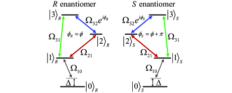
Each of the two opposite enantiomers can be modeled simultaneously as the four-level chiral-molecule model consisting of a cyclic three-level subsystem and an auxiliary level as shown in Fig. 1. Here, the indices and are introduced to represent respectively the and enantiomers which are mirror symmetry of each other. and () are respectively the desired -th eigen-states of and enantiomers. Here, we neglect the parity violating energy differences due to the fundamental weak force PVED-PRL2000 ; PVED-PRA2001 ; PVED-JCP2001 , thus and are with the same eigen-energy . Moreover, we also neglect any tunneling between enantiomers. Three strong driving fields with amplitudes , , and and frequencies , , and , are applied to resonantly couple respectively the transitions , , and () via the electric-dipole couplings. Thus it forms the cyclic three-level subsystem among , , and . Meanwhile, a weak probe field with frequency couples the ground state to the cyclic three-level subsystem via the transition .
Under the dipole approximation and rotating-wave approximation, the Hamiltonian in the interaction picture with respect to is given as
| (1) |
Here, denotes the detuning of probe field. describes the Rabi frequencies corresponding to the optical field with the electric-dipole transition moment of the transition . Without loss of generality, all these Rabi frequencies () have been assumed to be positive. is the overall phases of the three Rabi frequencies corresponding to the cyclic three-level subsystem for the pure () and () enantiomers. The chirality of this model is specified by choosing the overall phases of the and enantiomers as
| (2) |
The dynamical evolution of the system is described by the master equations MasterEq ; Pelzer-decoherence1 ; Pelzer-decoherence2 as
| (3) |
Here, denotes the decoherence Pelzer-decoherence1 ; Pelzer-decoherence2 with
| (4) |
where
| (5) |
where denotes the pure population relaxation rate from state to resulting from spontaneous emission and inelastic collision process while represents the pure dephasing rate arising from elastic collision process Pelzer-decoherence1 ; Pelzer-decoherence2 ; Doyle-2012decoherenceValue .
II.2 Light deflection in a medium of pure enantiomers
Light deflection phenomenon in a medium is the consequence of spatial variation of refractive index ZhouLan-2007HomoDeflection ; ZhouLan-2008HomoDeflection ; Kumar-2016HomoDeflection . In order to estimate the deflection angle of the probe light, we begin with the (general) geometrical optics differential equation in the vector form OptPrinciples
| (6) |
where represents the length of the probe light trajectory in medium. is the length variation of the light ray during propagation. denotes a point on light ray where and are unit vectors along the axes. is the spatially dependent refractive index corresponding to the probe light. For simplicity, we consider that the probe light injects the medium along direction at position . Here, we assume that the refractive index is only inhomogeneous in direction, then its gradient [i.e. ] can reduce to . In the small deflection angle regime, the gradient of refractive index along the probe light trajectory is approximatively equal to that at the incident position
| (7) |
where denotes the derivative of refractive index with respect to . The Eq. (6) implies that the propagation trajectory of the probe light is determined by the refractive index of the medium. Thus, we then use the master equations (3) to derive the steady-state optical response which determines the refractive index corresponding to the probe light in a medium of pure enantiomers.
Here, we follow the method in Ref. Perturbation to obtain the linear optical response which can sufficiently reflect the main physical properties of the propagation of the probe light. Moreover, we now focus on the ideal zero-temperature case (), where only the ground state is occupied initially. In the weak probe field approximation () and steady-state condition (i.e., ), the zeroth-order steady-state solution of the element is zero and the first-order steady-state solution of the element which determines the linear optical response for the probe light is given by (see the Appendix A)
| (8) |
with
| (9) |
where . Further, the linear susceptibility of a homogeneous medium of pure enantiomers with molecular density is defined as QuantumOptics ; Susceptibility
| (10) |
where represents the permittivity of vacuum. Since in the gaseous medium whose density is low, the corresponding refractive index of the probe light is approximately determined by
| (11) |
Once the medium is driven by inhomogeneous optical fields, a spatial variation of refractive index which is essential in light deflection can be induced for the probe light. Here, we assume that is homogeneous in space while and have the Gaussian profiles as
| (12) |
where [] characters the peak value of the Rabi frequencie and represents the beam radius.
Therefore, by replacing () in the Eqs. (6) and (7) with (), we can derive the propagation trajectory of the probe light which travels in the medium of pure or enantiomers ZhouLan-2007HomoDeflection
| (13) |
In the small deflection angle regime, the deflection angle of the probe light when it exits from the medium can be finally estimated as ZhouLan-2007HomoDeflection
| (14) |
where is the length of the medium along direction. As a result, the propagation trajectory and deflection angle of the probe light can be determined by Eqs. (13) and (14).
II.3 Example of 1,2-propanediol
So far, the deflection angle of the probe light in a homogeneous medium of pure enantiomers has been analyzed based on the related steady-state optical response. Specifically, in the following simulations, 1,2-propanediol PropanediolParameter09 ; PropanediolParameter17 is taken as an example to demonstrate our method. In view of the spatial degeneracy of states DegeneracyLehmann ; YeChong-RealLoop ; Leibscher-2019thermalpop ; DegeneracyLehmannAR1 ; DegeneracyLehmannAR2 ; anglemomentum , we choose the corresponding working states of the four-level chiral-molecule model as , , , and where () denotes the corresponding vibrational ground (first-excited) state for the motion dominated by a rocking in the carbon backbone PropanediolParameter17 . Here, the rotational states are marked in the notation DegeneracyLehmann ; Leibscher-2019thermalpop ; anglemomentum . is the angular moment quantum number. runs from to and runs from to with decreasing energy anglemomentum . denotes the magnetic quantum number. Thus, the transitions , , and are respectively coupled to a linearly -polarized () and two circularly-polarized () microwave fields whose Rabi frequencies are typical in the current experimental conditions Doyle-2013DiscriminationLoop ; Doyle-2013ChiralTWMLoop . Meanwhile, the infrared transition is coupled to a circularly-polarized () weak probe field. Note that the rotational transition dipole moment (of 1,2-propanediol) can be of the order of PropanediolParameter09 ; PropanediolParameter17 , thus we here take the estimated vibrational transition dipole moment since the dipole moment of vibrational transition is generally smaller than that of rotational transition Leibscher-2019thermalpop . Moreover, the bare transition frequencies are given by , , and based on the rotational constants for the vibrational first-excited state of lowest energy conformer of 1,2-propanediol , , and PropanediolParameter09 ; PropanediolParameter17 ; anglemomentum . Meanwhile, the transition frequency can be calculated based on the corresponding transition frequency between vibrational ground and first-excited states PropanediolParameter17 ; anglemomentum .
In the simulations, the decoherence, which is described by the master equation (3), includes these two types: pure population relaxation and pure dephasing Doyle-2012decoherenceValue ; Smith-1999decay ; Shapiro-2006Decay ; Pelzer-decoherence1 ; Pelzer-decoherence2 . Specifically, we here choose , , and vib-ro-book1 ; vib-ro-book2 ; Doyle-2012decoherenceValue ; Doyle-2017decoherenceValue according to the typical experimental conditions Doyle-2012decoherenceValue ; Doyle-2017decoherenceValue . Moreover, the length of the medium is reasonably taken as Doyle-2017decoherenceValue .
II.4 Detecting the chirality of pure enantiomers via light deflection
Before illustrating how to detect the chirality of pure enantiomers via monitoring the deflection angle of the probe light, we explain the physical mechanism underlying our method as following. According to Eq. (2), the media which composes of pure or enantiomers could result in chirality-dependent refractive index for the probe light [see Eq. (11)]. When two of the three strong driving fields are spatially inhomogeneous [e.g. and given in Eq. (12)], the resultant gradient of refractive index will become chirality-dependent. In terms of the Fermat’s principle OptPrinciples , the probe light traveling in the medium of pure enantiomers is always along the trajectory taking the least time. Thus, such a chirality-dependent gradient of refractive index can lead to completely different propagation trajectories of the probe light. As a consequence, the chirality of pure enantiomers can be distinguished by monitoring the corresponding deflection angle of the probe light in principle.
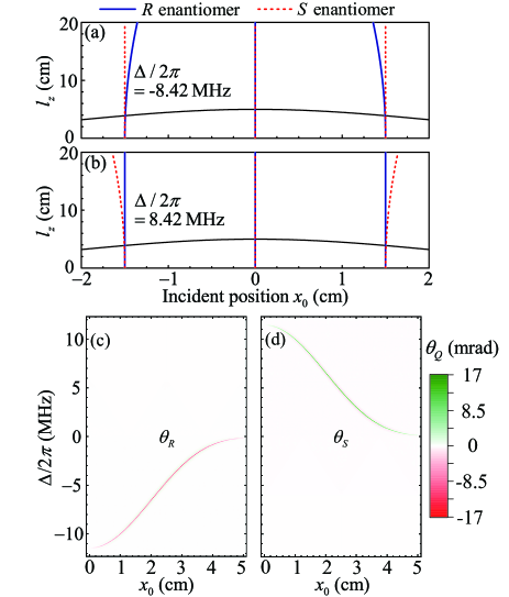
In Fig. 2 we give the propagation trajectory of the probe light in the medium of pure or enantiomers at different incident positions . Fig. 2(a) shows that a blue-detuned () probe light experiences a “attractive potential” away from the central position of Gaussian driving field for the medium of pure enantiomers, while it travels almost along direction for the medium of enantio-pure enantiomers. On the contrary, it is shown in Fig. 2(b) that a red-detuned () probe light feels an “repulsive potential” for the medium of pure enantiomers but propagates almost along direction for the medium of pure enantiomers. This means that the two opposite enantiomers can be identified by measuring the deflection angle of the probe light. However, it is worth noting that the deflection angle is sensitive to the incident position . For example, when the incident position is set to be , neither the blue-detuned () [Fig. 2(a)] nor red-detuned () [Fig. 2(b)] probe light has significant deflection when it propagates in the medium of pure or enantiomers.
To find the working region where the probe light has a significant deflection, we further display the deflection angle corresponding to pure and enantiomers versus the incident position and detuning of the probe field in Fig. 2(c) and Fig. 2(d), respectively. Here, we only present the results in the region (e.g. ) since () is symmetric in space [see Eq. (12)]. As one can see, if the incident position is set properly, the medium of pure enantiomers could lead to negative deflection angle at the detuning regions [Fig. 2(c)], while the medium of pure enantiomers could result in positive deflection angle at the detuning regions [Fig. 2(d)]. That means the working regions for the two opposite enantiomers are well separated. This chirality-dependent phenomenon is useful in detecting the chirality of pure enantiomers. Consequently, we should adjust the parameters and find the working regions, then the chirality of pure enantiomers can be distinguished by monitoring the corresponding sign of the deflection angle of the probe light. Additionally, one can find that the deflection angle will be larger if the probe light enters the medium at the position . Hence, for simplicity, we assume the incident position of the probe light to be in the following discussions.
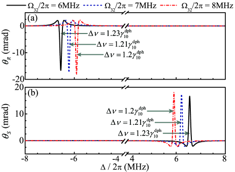
The deflection angle of the probe light should be large enough to ensure that our method can act as a tool for enantio-discrimination. This immediately raises the interesting question weather the deflection angle can be controlled effectively. In Fig. 3, we plot the deflection angle of the probe light corresponding to pure and enantiomers as a function of detuning for different Rabi frequencies corresponding to the homogeneous driving field []. One can find that the deflection angle strongly depends on : it increases with the enhancement of due to the increase of gradient of refractive index. Namely, we can manipulate the deflection phenomenon by tuning the Rabi frequency to induce larger deflection angle as required. However, should be limited in the typical region of parameters [] according to the current experimental conditions Doyle-2013DiscriminationLoop ; Doyle-2013ChiralTWMLoop . In recent molecular cooling experiments Doyle-2013DiscriminationLoop ; Doyle-2013ChiralTWMLoop ; Doyle-2012decoherenceValue ; Dopplerwidth , molecules can be cooled to the temperature of the order of 1 K (in the absence of microwave field). With the further development of molecular cooling technology, it is expected to prepare molecules with lower temperature. Thus, even under the heating of microwave fields, it would be still attainable to prepare molecules with temperature of the order of 1 K. Moreover, we also give the peak width of the deflection angle (related to the pure dephasing rate ) in Fig. 3. One can find that depends on : it decreases with the enhancement of . Note that the deflection angle here is dependent on the the first derivative of refractive index with respect to [see Eq. (14)]. Thus, the lineshape of the deflection peak here is different from that of the absorption peak (whose lineshape is Lorentzian JiaWZ-2011DiscriminationLoop ).
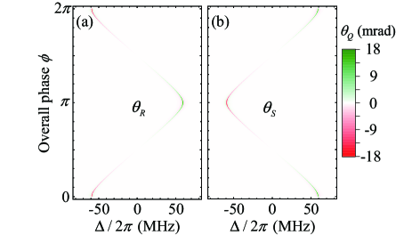
In realistic case, the overall phase of three microwave fields , which has been taken to be in Figs. 2 and 3, is a tunable parameter. To investigate the effect of on the deflection angle, we display the deflection angle corresponding to pure and enantiomers versus the overall phase and detuning of the probe field in Fig. 4(a) and Fig. 4(b). One can find that the deflection angle corresponding to pure () enantiomers, (), changes from negative (positive) deflection angle to positive (negative) one gradually when ranges from to . Further, when ranges from to , the corresponding () turns from positive (negative) deflection angle to negative (positive) one. This indicates that the chirality of pure enantiomers can also be distinguished by monitoring the deflection angle as function of detuning with overall phase cycling, which is experimentally practical. Meanwhile, Fig. 4 also shows that the deflection angle will be optimal when the overall phase is taken to be , , and . Moreover, our scheme requires that the three microwave fields are phase locked to each other. Note that many experimental schemes have utilized such phase-locking among three microwave fields to achieve state-specific enantiomeric transfer Doyle-2017decoherenceValue ; Schnell-2017TransferLoop based on the cyclic three-level model. Namely, the phase-locking is in fact possible given today’s technology in experiments.
III DETECTING ENANTIOMERIC EXCESS OF CHIRAL MIXTURE
In the above section, we have demonstrated that the chirality of pure enantiomers can be detected by monitoring the deflection angle of the probe light. Further, such a chirality-dependent deflection angle can also be utilized to detect the enantiomeric excess of chiral mixture.
III.1 Light deflection in a medium of chiral mixture
We now turn to consider the probe light propagating in a medium of chiral mixture. In this case, both kinds of and enantiomers in the medium have effect on the propagation trajectory of the probe light, thus the linear susceptibility of a homogeneous medium of chiral mixture with molecular density is written as
| (15) |
where and can be derived via Eq. (10). Now, and are, respectively, the molecular densities of and enantiomers in the medium of chiral mixture. Based on Eq. (11), the corresponding refractive index of the probe light is approximately equal to
| (16) |
According to the above approximation, the derivative of refractive index with respect to is given as
| (17) |
The propagation trajectory of the probe light in the medium of chiral mixture is also described by the geometrical optics differential equation (6). Therefore, based on the calculations in Sec. II, we can estimate the deflection angle of the probe light given by
| (18) |
with
| (19) |
Here, and can be used to respectively describe the contributions of and enantiomers to the deflection angle of probe light. In the next subsection, we will illustrate how to detect the enantiomeric excess of chiral mixture via such a deflection angle.
III.2 Detecting the enantiomeric excess of chiral mixture via light deflection
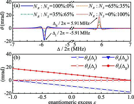
As shown in the last section, each of the two opposite enantiomers can lead to prominent light deflection at one regions [the region for pure enantiomers in Fig. 2(c), and the region for pure enantiomers in Fig. 2(d)]. In Fig. 5(a), we show the deflection angle of the probe light versus the detuning of the probe light () for different percentages of two opposite enantiomers in the chiral mixture. Apparently, there are two characteristic peaks of deflection angle at and . It is shown that the amplitude of deflection angle at the detuning is larger (smaller) than that at when the density of enantiomers ( enantiomers) in the chiral mixture is dominant. These results suggest that the percentages of the two opposite enantiomers are directly associated with the deflection angles of the probe light at the two characteristic detunings. To further investigate this property, in Fig. 5(b), we display , , , and as a function of the enantiomeric excess which is defined as . As one can see, at the detuning (), the contributions of enantiomers ( enantiomers) is prominent while that of enantiomers ( enantiomers) tends to be negligible. This implies that, in appropriate region of parameters, the contributions of enantiomers ( enantiomers) to the deflection angle at the detuning () can be approximately reduced to
| (20) |
Applying this approximation to Eq. (18), we can obtain
| (21) |
As a result, the enantiomeric excess of chiral mixture can be estimated as
| (22) |
where the subscript “” denotes the estimation value. Therefore, in order to detect the enantiomeric excess of chiral mixture, we should adjust the parameters to find two characteristic peaks for the light deflection angle at two different detunings of probe light where the corresponding amplitudes of two deflection angles are approximately proportional to the densities of enantiomers and enantiomers, respectively.
Moreover, it is worth mentioning that the approximation in Eq. (20) can be ensured when pure and enantiomers could respectively lead to significant deflection of the probe light at different working regions [see in Fig. 2(c) and Fig. 2(d)]. However, if there are overlaps between the working region related to pure enantiomers and that related to enantiomers, the corresponding estimation precision will suffer from such overlap due to the failure of and . Therefore, it is necessary to evaluate the estimation precision of our method. Here, we introduce the absolute error
| (23) |
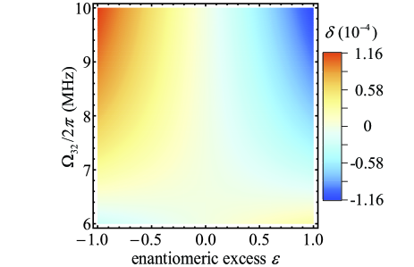
to describe the estimation precision and verify the robustness of against a variation of the enantiomeric excess and Rabi frequency in Fig. 6. One can find that an affordable absolute error (below ) is fairly robust against the variation of and in the range and .
IV Discussion
The principle of our method is based on the light deflection effect in a homogeneous medium of chiral molecules subjected to inhomogeneous external fields. In the above simulations, the frequency of the probe field is of the order of 1 THz. Therefore, in principle, a device sensitive to the positional change of the optical field whose frequency is of the order of 1 THz would be required to make sure that the corresponding deflection angle can be detected.Moreover, in the above simulations, we use the geometrical optics differential equation [Eq. (6)] to estimate the deflection angle of the probe field since it is a valid tool for investigate the propagation trajectory of the probe field ZhouLan-2007HomoDeflection ; Kumar-2016HomoDeflection ; ZhouLan-2009DeflectionAppl ; Scully-2010DeflectionAppl ; ZhuChengJie-2013DeflectionAppl . In practice, the beam size of the probe field should be an important consideration since it would lead to the broadening of the frequencies of the deflection peaks. We will consider to investigate this issue in the future work.
In the above investigation, we only focus on the ideal zero-temperature case (), where the molecules only occupy the ground state, thus the corresponding ground-state molecular density is equal to the molecular density (similarly and ). In realistic experiments Doyle-2013DiscriminationLoop ; Lehmann-2015DiscriminationLoop ; Schnell-2015DiscriminationLoop ; Schnell-2017TransferLoop ; Leibscher-2019thermalpop , even under “cold” conditions, many molecular ro-vibrational states are thermally occupied due to the effect of environment temperature. However, note that almost only the ground vibrational state () is thermally occupied in “cold” experiments Doyle-2013DiscriminationLoop ; Lehmann-2015DiscriminationLoop ; Schnell-2015DiscriminationLoop ; Schnell-2017TransferLoop ; Leibscher-2019thermalpop due to the large vibrational transition frequency (in the infrared range) Leibscher-2019thermalpop . Thus, among the four states , , , and , almost only the ground state () is occupied at finite temperature. Even so, under the cooled condition, there still exist other rotational states of the ground vibrational state like which are thermally occupied. For the temperature , the thermal population on the rotational state of ground vibrational state with eigen-energy PropanediolParameter09 ; PropanediolParameter17 ; anglemomentum is given by where is the Boltzmann constant, and denotes the sum for all rotational states (for given ground vibrational state ). Specially, at typical temperature about Doyle-2012decoherenceValue ; Dopplerwidth , the proportion of state (i.e., the ground state of the four-level chiral-molecule model) to the total molecules due to thermal occupation is about for the ground vibrational state PropanediolParameter09 ; PropanediolParameter17 . As a result, the corresponding ground-state molecular density is less than the molecular density . Based on this, to ensure that the above results (i.e., Figs. 2, 3, 4, 5, and 6) can remain unchanged for typical temperature about , we should take the ground-state () molecular density to be [i.e., the molecular density (similarly and ) mentioned in above discussion should be replaced by the ground-state molecular density], and thus the corresponding molecular density should be increased to about which is still attainable in today’s buffer gas cooling experiment Doyle-2013DiscriminationLoop ; Doyle-2017decoherenceValue ; Doyle-2012decoherenceValue .
Moreover, in realistic case, the non-zero temperature would in fact lead to inevitable Doppler effect Dopplerwidth ; DopplerSuppress ; Doppler1 ; Doppler2 , and then a reasonable Doppler broadening of the transition should be taken into consideration. Spectically, for the temperature Doyle-2012decoherenceValue ; Dopplerwidth , the corresponding Doppler full width at half maximum (defined as ) Dopplerwidth here is about (based on the parameters: mass of 1,2-propanediol , central transition frequency , Boltzmann constant , and light speed in vacuum ) PropanediolParameter09 ; PropanediolParameter17 . Such a Doppler broadening could normally reasult in the broadening of spectral lines which may obscure the characteristic peaks. However, by taking appropriate Rabi frequencies to ensure the characteristic peaks are separated from each other sufficiently DopplerSuppress ; JiaWZ-2011DiscriminationLoop (i.e., ensuring and ), the similar chirality-dependent light deflection could be still observed. On the other hand, the Doppler broadening would also lead to the suppression of deflection angle since the Doppler width here is larger than the peak width of deflection angle [see Fig. 3]. However, note that molecules can be cooled to the temperature on the order of in recent molecular cooling experiments Doyle-2013DiscriminationLoop ; Doyle-2013ChiralTWMLoop ; Doyle-2012decoherenceValue ; Dopplerwidth , it is expected to prepare molecules with lower temperature (below K) in the near future, and then the corresponding effect of Doppler broadening can be suppressed further.
Finally, in the schemes for enantio-discrimination based on cyclic three-level models JiaWZ-2011DiscriminationLoop ; Hirota-2012DiscriminationLoop ; Doyle-2013DiscriminationLoop ; Doyle-2013ChiralTWMLoop ; Doyle-2014ChiralTWMLoop ; Lehmann-2015DiscriminationLoop ; Schnell-2014DiscriminationLoop ; Schnell-2015DiscriminationLoop ; Lehmann-2017DiscriminationLoop , phase matching among the electromagnetic fields is an important consideration Lehmann-2017DiscriminationLoop ; DegeneracyLehmann . In practice, to ensure the overall phase can be approximately the same for all molecules (which means that the phase matching is fulfilled), the product of the apparatus characteristic length and phase mismatching wave vector should meet the requirement (with where denotes the wavelength). Following the method in Refs. Lehmann-2017DiscriminationLoop ; DegeneracyLehmann (i.e., taking one of the transition frequencies for the three-level model as small as possible), the effect of phase mismatching here can be minimized by taking and to be parallel and to be perpendicular to them. Then, for an apparatus characteristic length about and wave vector , the corresponding phase mismatching is which can meet the requirement , thus effect of phase mismatching is negligible.
V CONCLUSION
In conclusion, we have proposed a theoretical method for enantio-discrimination based on the light deflection effect in a four-level chiral-molecule model consisting of a cyclic three-level subsystem and an auxiliary level. The key idea is to induce spatially inhomogeneous refractive index which is chirality-dependent using inhomogeneous driving fields, and then the chirality of pure enantiomers can be mapped on the deflection angle of the probe light. We also investigate the effect of the Rabi frequency of the driving field on the deflection angle and the results show that the amplitude of deflection angle can be controlled effectively via such a Rabi frequency. Further, we demonstrate that such a chirality-dependent light deflection angle can also be utilized to detect the enantiomeric excess of chiral mixture with uniform molecular density. Moreover, we also evaluate the measurement precision of our method. It is shown that we can obtain affordable measurement precision which is fairly robust against a small variation in the Rabi frequency and enantiomeric excess. Therefore, our method may act as a tool for enantio-discrimination.
Supplementary Material
See supplementary material for the complete calculation of the first-order steady-state solution which determines the linear optical response for the probe light. Moreover, the figure about the comparison between and is given in the supplementary material.
acknowledgments
This work was supported by the National Key R&D Program of China (Grant No. 2016YFA0301200), the Natural Science Foundation of China (Grants No. 11774024, No. 11534002, No. U1930402, and No. 11947206), and the Science Challenge Project (Grant No. TZ2018003).
Data Availability Statements
The data that supports the findings of this study are available within the article [and its supplementary material].
References
References
- (1) R. G. Wooley, “Quantum theory and molecular structure,” Adv. Phys. 25, 27-52 (1976).
- (2) N. P. Franks and W. R. Lieb, “Stereospecific Effects of Inhalational General Anesthetic Optical Isomers on Nerve Ion Channels,” Science 254, 427-430 (1991).
- (3) K. Bodenhofer, A. Hierlemann, J. Seemann, G. Gauglitz, B. Koppenhoefer, and W. Gopel, “Chiral Discrimination Using Piezoelectric and Optical Gas Sensors,” Nature 387, 577-580 (1997).
- (4) E. A. Power and T. Thirunamachandran, “Maxwell Fields Near a Chiral Molecule: Application to Induced Circular Dichroism,” Proc. R. Soc. Lond. A 396, 155-163 (1984).
- (5) P. J. Stephens, “Theory of Vibrational Circular Dichroism,” J. Phys. Chem. 89, 748-752 (1985).
- (6) P. L. Polavarapu, S. T. Pickard, H. E. Smith, T. M. Black, L. D. Barron, and L. Hecht, “Determination of absolute configurations from vibrational raman optical activity: Trans-2,3-dimethylthiirane,” Talanta 40, 545-549 (1993).
- (7) R. McKendry, M. E. Theoclitou, T. Rayment, and C. Abell, “Chiral discrimination by chemical force microscopy,” Nature 391, 566-568 (1998).
- (8) G. L. J. A. Rikken and E. Raupach, “Enantioselective magnetochiral photochemistry,” Nature 405, 932-935 (2000).
- (9) H. Zepik, E. Shavit, M. Tang, T. R. Jensen, K. Kjaer, G. Bolbach, L. Leiserowitz, I. Weissbuch, and M. Lahav, “Chiral Amplification of Oligopeptides in Two-Dimensional Crystalline Self-Assemblies on Water,” Science 295, 1266-1269 (2002).
- (10) R. Bielski and M. Tencer, “Absolute enantioselective separation: Optical activity ex machina,” J. Sep. Sci. 28, 2325-2332 (2005).
- (11) R. K. Kondru, Peter Wipf, and D. N. Beratan, “Atomic contributions to the optical rotation angle as a quantitative probe of molecular chirality,” Science 282, 2247-2250 (1998).
- (12) P. J. Stephens, F. J. Devlin, J. R. Cheeseman, M. J. Frisch, O. Bortolini, and P. Besse, “Determination of absolute configuration using ab initio calculation of optical rotation,” Chirality 15, S57-S64 (2003).
- (13) H. Rhee, J. S. Choi, D. J. Starling, J. C. Howelld, and M. Cho, “Amplifications in chiroptical spectroscopy, optical enantioselectivity, and weak value measurement,” Chem. Sci. 4, 4107-4114 (2013).
- (14) X. D. Qiu, L. G. Xie, X. Liu, L. Luo, Z. Y. Zhang, and J. L. Du, “Estimation of optical rotation of chiral molecules with weak measurements,” Opt. Lett. 41, 4032-4035 (2016).
- (15) D. M. Li, T. Guan, F. Liu, A. P. Yang, Y. H. He, Q. H. He, Z. Y. Shen, and M. G. Xin, “Optical rotation based chirality detection of enantiomers via weak measurement in frequency domain,” Appl. Phys. Lett. 112, 213701 (2018).
- (16) L. D. Barron, Molecular Light Scattering and Optical Activity (Cambridge University Press, Cambridge, UK, 1982).
- (17) A. Ghosh and P. Fischer, “Chiral Molecules Split Light: Reflection and Refraction in a Chiral Liquid,” Phys. Rev. Lett. 97, 173002 (2006).
- (18) A. Ghosh, F. M. Fazal, and P. Fischer, “Circular differential double diffraction in chiral media,” Opt. Lett. 32, 1836-1838 (2007).
- (19) R. P. Rajan and A. Ghosh, “Enhancement of circular differential deflection of light in an optically active medium,” Opt. Lett. 37, 1232-1234 (2012).
- (20) Y. Liu, J. Q. You, L. F. Wei, C. P. Sun, and F. Nori, “Optical Selection Rules and Phase-Dependent Adiabatic State Control in a Superconducting Quantum Circuit,” Phys. Rev. Lett. 95, 087001 (2005).
- (21) C. Ye, Q. Zhang, and Y. Li, “Real single-loop cyclic three-level configuration of chiral molecules,” Phys. Rev. A 98, 063401 (2018).
- (22) Y. Li, C. Bruder, and C. P. Sun, “Generalized Stern-Gerlach Effect for Chiral Molecules,” Phys. Rev. Lett. 99, 130403 (2007).
- (23) Y. Li and C. Bruder, “Dynamic method to distinguish between left- and right-handed chiral molecules,” Phys. Rev. A 77, 015403 (2008).
- (24) X. Li and M. Shapiro, “Theory of the optical spatial separation of racemic mixtures of chiral molecules,” J. Chem. Phys. 132, 194315 (2010).
- (25) W. Z. Jia and L. F. Wei, “Distinguishing left- and right-handed molecules using two-step coherent pulses,” J. Phys. B: At. Mol. Opt. Phys. 43, 185402 (2010).
- (26) N. V. Vitanov and M. Drewsen, “Highly Efficient Detection and Separation of Chiral Molecules through Shortcuts to Adiabaticity,” Phys. Rev. Lett. 122, 173202 (2019).
- (27) J. L. Wu, Y. Wang, J. Song, Y. Xia, S. L. Su, and Y. Y. Jiang, “Robust and highly efficient discrimination of chiral molecules through three-mode parallel paths,” Phys. Rev. A 100, 043413 (2019).
- (28) W. Z. Jia and L. F. Wei, “Probing molecular chirality by coherent optical absorption spectra,” Phys. Rev. A 84, 053849 (2011).
- (29) E. Hirota, Proc. “Triple resonance for a three-level system of a chiral molecule,” Jpn. Acad. Ser. B 88, 120-128 (2012).
- (30) D. Patterson, M. Schnell, and J. M. Doyle, “Enantiomer-specific detection of chiral molecules via microwave spectroscopy,” Nature 497, 475-477 (2013).
- (31) D. Patterson and J. M. Doyle, “Sensitive Chiral Analysis via Microwave Three-Wave Mixing,” Phys. Rev. Lett. 111, 023008 (2013).
- (32) D. Patterson and M. Schnell, “New studies on molecular chirality in the gas phase: enantiomer differentiation and determination of enantiomeric excess,” Phys. Chem. Chem. Phys. 16, 11114-11123 (2014).
- (33) S. Lobsiger, C. Pérez, L. Evangelisti, K. K. Lehmann, and B. H. Pate, “Molecular Structure and Chirality Detection by Fourier Transform Microwave Spectroscopy,” J. Phys. Chem. Lett. 6, 196-200 (2015).
- (34) V. A. Shubert, D. Schmitz, D. Patterson, J. M. Doyle, and M. Schnell, “Identifying Enantiomers in Mixtures of Chiral Molecules with Broadband Microwave Spectroscopy,” Angew. Chem. Int. Ed. 53, 1152-1155 (2014).
- (35) V. A. Shubert, D. Schmitz, C. Pérez, C. Medcraft, A. Krin, S. R. Domingos, D. Patterson, and M. Schnell, “Chiral Analysis Using Broadband Rotational Spectroscopy,” J. Phys. Chem. Lett. 7, 341-350 (2015).
- (36) K. K. Lehmann, in Frontiers and Advances in Molecular Spectroscopy edited by J. Laane (Elsevier, 2018), Vol. 2, pp. 713-743.
- (37) S. Eibenberger, J. M. Doyle, and D. Patterson, “Enantiomer-Specific State Transfer of Chiral Molecules,” Phys. Rev. Lett. 118, 123002 (2017).
- (38) M. Gottlieb, C. L. M. Ireland, and J. M. Ley, Electro-Optic and Acousto-Optic Scanning and Deflection (Dekker, New York, 1983).
- (39) R. R. Moseley, S. Shepherd, D. J. Fulton, B. D. Sinclair, and M. H. Dunn, “Spatial Consequences of Electromagnetically Induced Transparency: Observation of Electromagnetically Induced Focusing,” Phys. Rev. Lett. 74, 670-673 (1995).
- (40) R. Holzner, P. Eschle, S. Dangel, R. Richard, H. Schmid, U. Rusch, and B. Röhricht, “Observation of Magnetic-Field-Induced Laser Beam Deflection in Sodium Vapor,” Phys. Rev. Lett. 78, 3451-3454 (1997).
- (41) L. Karpa and M. Weitz, “A Stern–Gerlach experiment for slow light,” Nat. Phys. 2, 332-335 (2006).
- (42) D. L. Zhou, L. Zhou, R. Q. Wang, S. Yi, and C. P. Sun, “Deflection of slow light by magneto-optically controlled atomic media,” Phys. Rev. A 76, 055801 (2007).
- (43) Y. Guo, L. Zhou, L. M. Kuang, and C. P. Sun, “Magneto-optical Stern-Gerlach effect in an atomic ensemble,” Phys. Rev. A 78, 013833 (2008).
- (44) P. Kumar and S. Dasgupta, “Light deflection by light: Effect of incidence angle and inhomogeneity,” Phys. Rev. A 94, 043845 (2016).
- (45) Q. Q. Sun, Y. V. Rostovtsev, and M. S. Zubairy, “Optical beam steering based on electromagnetically induced transparency,” Phys. Rev. A 74, 033819 (2006).
- (46) H. R. Zhang, L. Zhou, and C. P. Sun, “Birefringence lens effects of an atom ensemble enhanced by an electromagnetically induced transparency,” Phys. Rev. A 80, 013812 (2009).
- (47) V. A. Sautenkov, H. B. Li, Y. V. Rostovtsev, and M. O. Scully, “Ultradispersive adaptive prism based on a coherently prepared atomic medium,” Phys. Rev. A 81, 063824 (2010).
- (48) C. J. Zhu, L. Deng, E. W. Hagley, and M. L. Ge, “Optical cloaking using alternate Raman gain and free-space media in the presence of spatially distributed pump fields,” Phys. Rev. A 88, 045804 (2013).
- (49) O. N. Verma and T. N. Dey, “Steering, splitting, and cloning of an optical beam in a coherently driven Raman gain system,” Phys. Rev. A 91, 013820 (2015).
- (50) M. Shapiro, E. Frishman, and P. Brumer, “Coherently Controlled Asymmetric Synthesis with Achiral Light,” Phys. Rev. Lett. 84, 1669-1672 (2000).
- (51) P. Brumer, E. Frishman, and M. Shapiro, “Principles of electric-dipole-allowed optical control of molecular chirality,” Phys. Rev. A 65, 015401 (2001).
- (52) D. Gerbasi, M. Shapiro, and P. Brumer, “Theory of enantiomeric control in dimethylallene using achiral light,” J. Chem. Phys. 115, 5349-5349 (2001).
- (53) E. Frishman, M. Shapiro, and P. Brumer, “Optical purification of racemic mixtures by ‘laser distillation’ in the presence of a dissipative bath,” J. Phys. B 37, 2811-2821 (2004).
- (54) A. W. Pelzer, S. Ramakrishna, and T. Seideman, “Optimal control of molecular alignment in dissipative media” J. Chem. Phys. 126, 034503 (2007).
- (55) A. W. Pelzer, S. Ramakrishna, and T. Seideman, “Optimal control of rotational motions in dissipative media,” J. Chem. Phys. 129, 134301 (2008).
- (56) D. Patterson and J. M. Doyle, “Cooling molecules in a cell for FTMW spectroscopy,” Mol. Phys. 110, 1757-1766 (2012).
- (57) M. Born and E. Wolf, Principles of Optics (Cambridge University Press, Cambridge, UK, 1999).
- (58) L. Zhou, J. Lu, D. L. Zhou, and C. P. Sun, “Quantum theory for spatial motion of polaritons in inhomogeneous fields,” Phys. Rev. A 77, 023816 (2008).
- (59) M. O. Scully and M. S. Zubairy, Quantum Optics (Cambridge University Press, Cambridge, UK, 1997).
- (60) S. E. Harris and Y. Yamamoto, “Photon Switching by Quantum Interference,” Phys. Rev. Lett. 81, 3611-3614 (1998).
- (61) F. J. Lovas, D. F. Plusquellic, B. H. Pate, J. L. Neill, M. T. Muckle, and A. J. Remijan, “Microwave spectrum of 1,2-propanediol,” J. Mol. Spectrosc. 257, 82-93 (2009).
- (62) B. E. Arenas, S. Gruet, A. L. Steber, and M. Schnell, “A global study of the conformers of 1,2-propanediol and new vibrationally excited states,” J. Chem. Phys. 337, 9-16 (2017).
- (63) R. N. Zare, Angular Momentum (Wiley, New York, 1988).
- (64) K. K. Lehmann, arXiv:1501.05282 (2015).
- (65) K. K. Lehmann, arXiv:1501.07874 (2015).
- (66) K. K. Lehmann, “Influence of spatial degeneracy on rotational spectroscopy: Three-wave mixing and enantiomeric state separation of chiral molecules,” J. Chem. Phys. 149, 094201 (2018).
- (67) M. Leibscher, T. F. Giesen, and C. P. Koch, “Principles of enantio-selective excitation in three-wave mixing spectroscopy of chiral molecules,” J. Chem. Phys. 151, 014302 (2019).
- (68) A. E. Belikov and M. A. Smith, “State-to-state rate coefficients for rotational relaxation of CO in Ar,” J. Chem. Phys. 110, 8513 (1999).
- (69) E. Frishman and M. Shapiro, “Control of spontaneous emission in the presence of collisions,” J. Chem. Phys. 124, 084309 (2006).
- (70) G. Scoles, Atomic and Molecular Beam Methods (Oxford University Press, Oxford, 1988).
- (71) H. Pauly, Atom, Molecule, and Cluster Beams I (Springer-Verlag, Cambridge, 2000).
- (72) C. Pérez, A. L. Steber, S. R. Domingos, A. Krin, D. Schmitz, and M. Schnell, “Coherent Enantiomer-Selective Population Enrichment Using Tailored Microwave Fields,” Angew. Chem. Int. Ed. 56, 12512-12517 (2017).
- (73) N. R. Hutzler, H.-I. Lu, and J. M. Doyle, “The Buffer Gas Beam: An Intense, Cold, and Slow Source for Atoms and Molecules,” Chem. Rev. 112, 4803 (2012).
- (74) J.-U. Grabow, “Fourier Transform Microwave Spectroscopy: Handedness Caught by Rotational Coherence,” Angew. Chem. Int. Ed. 52, 11698-11700 (2013).
- (75) S. Tokunaga, C. Stoeffler, F. Auguste, A. Shelkovnikov, C. Daussy, A. Amy-Klein, C. Chardonnet, and B. Darquié, “Probing weak force-induced parity violation by high-resolution mid-infrared molecular spectroscopy,” Mol. Phys. 111, 2363-2373 (2013).
- (76) T. A. Isaev and R. Berger, “Polyatomic Candidates for Cooling of Molecules with Lasers from Simple Theoretical Concepts,” Phys. Rev. Lett. 116, 063006 (2016).