FLIP-FLexible IoT Path Programming Framework for Large-scale IoT
††thanks:
Abstract
With the rapid increase in smart objects forming IoT fabric, it is inevitable to see billions of devices connected together, forming large-scale IoT networks. This expeditious increase in IoT devices is giving rise to increased user requirements and network complexity. Collecting big data from these IoT devices with optimal network utilization and simplicity is becoming more and more challenging. This paper proposes FLIP- FLexible IoT Path Programming Framework for Large-scale IoT. The distinctive feature of FLIP is that it focuses on the IoT fabric from the perspective of user requirements and uses SDN techniques along with DPI technology to efficiently fulfill the user requirements and establish datapath in the network in an automated and distributed manner. FLIP utilizes SDN structure to optimize network utilization through in-network computing and automated datapath establishment, also hiding network complexity along the way. We evaluated our framework through experiments, and results indicate that FLIP has the potential to fulfill user requirements in an automated fashion and optimize network utilization.
Index Terms:
Software-defined Networks (SDN), Deep Packet Inspection(DPI)I Introduction
The Internet of Things (IoT) is an increasingly important and revolutionary paradigm for enabling the world of smart objects (SOs). An estimated 50 billion devices will be connected to the Internet by 2020 [1]. With this expansion, the user requirements for an IoT system are also increasing e.g. datapath selection, computation, delay, rate, jitter, and energy efficiency etc.
Software defined networking (SDN) brings about innovation, simplicity in network management, and configuration in network computing [2]. In recent times researchers have provided SDN based solutions to different IoT problems [3], [4]. But SDN also has its limitations. It is largely restricted to L2-L4 protocols [5] [6] [7] [8] [9] . It means that we cannot process the packets’ data above L4. There have been techniques proposed to tackle this limitation. Udechukwu et al. [5] uses a middlebox as a DPI engine to apply traffic engineering to get better video stream. Application based QoE support is proposed in [8] ,it also focuses on video streaming quality. Atlas framework [6] employs a machine learning (ML) based traffic classification technique. Bui et al. [9] came up with a generic interface to extend the Open vSwitch to recognize custom protocols but this interface is very limited and does not allow users to manipulate packet payload. Extended-SDN architecture [7] uses an extended table in the Open vSwitch called “application table” to keep track of packets based on L7 header information. It is worth mentioning that non of the above solutions are proposed for IoT systems. In contrast to the above techniques, our framework is designed in consideration to large-scale IoT. FLIP not only identifies L4-L7 headers but also processes the application layer payload which in most IoT cases can be helpful to reduce network resource utilization.
In this paper, we present a flexible IoT path programming framework that applies SDN techniques with External Processing Boxes (EPBs). The embedded DPI engine inside an EPB analyzes, processes, and forwards packets such that big IoT data is efficiently routed to the destination. Our contributions in this paper are three-fold. First, we propose an SDN-based IoT datapath programming framework using EPBs. Second, we define user requirements formally and design python-base script programming syntax to incorporate user requirements. Third, we propose an efficient data path computation algorithm that outputs network resource saving datapath while satisfying user requirements. Finally, the efficacy of the proposed algorithm is shown though microbenchmarking measuring packet counts at each switch.
The rest of this paper is organized as follows. Section II details the problem statement and the pertaining target network and user requirements. Section III explains the overall architecture of FLIP. Section IV provides an overview of the User command syntax of FLIP. Section V details FLIP’s flexible datapath installation and heuristics used for the datapath selection. Experiments to evaluate the framework performance are detailed in Section VI. Section VII provides a review of the related work. Section VIII concludes the paper.
II Problem Statement
In general, IoT data processing takes place at the servers or clouds designated by users. These days, most cloud computing providers provide IoT data processing services in their clouds. In the case of Amazon AWS, IoT devices send their data to the IoT Hub, and cloud computing resources subsequently process the data.
However, when there are tremendous numbers of IoT devices and users, network bottleneck and storage/computing resource wastage due to unnecessary data processing may not satisfy many users’ requirements properly. Suppose that we need the average value of data from millions of IoT devices. If all IoT devices send their data to servers or clouds, network traffic bottleneck or lack of computing resources for handling massive IoT data may hinder proper IoT data processing. Instead, if we may compute the average value in the network, and send the computed results, we can save network/computing resources, and also process IoT data properly. We propose efficient in-network processing of IoT data, which will reduce the amount of data arriving at servers or clouds and subsequently make it possible to cope with massive IoT data processing while meeting each user’s requirements. We define our target networks and problem in a formal way in the following subsections.
II-A Target Networks
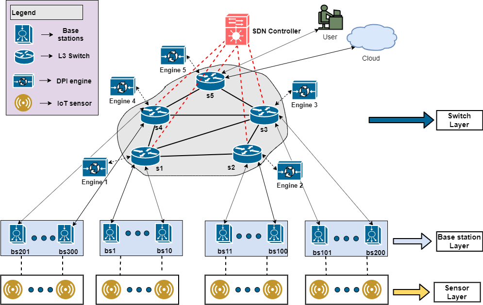
IoT networks and associated topology structures and access technology for communication vary depending on applications (e.g., smart home, smart grid, VANET, etc.). Hanes et al.[10] summarizes the commonly used topologies in IoT as star, mesh, partial mesh, and peer to peer. Huang et al.[11] proposes a three-layered (base station layer, relay node layer, and sensor layer) energy-efficient topology structure for IoT. A recent study also presents a three-tiered (Cloud tier, Fog Tier, and IoT tier) topology structure for the IoT [4]. Based on these recent studies we chose a three layered (Switch layer, Base station layer and Sensor layer) topology structure similar to [11]. Switch layer follows a partial-mesh topology model [10]. Base station layer and sensor layer follow the same hierarchical model as mentioned in [11] and [4]. we have selected a target network that can adapt to the referred topology structures easily.
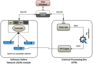
Fig. 1 shows our target network model. The SDN controller connects to L3-switches and has an overall visibility of the network. The L3-switch can be a software switch or a hardware switch. In case of software switch like Open vSwitch (OVS), both OVS and DPI engine can run on the same machine. While in hardware switch’s case, we assume a programmable switch (e.g. Cisco’s Nexus 3000) with internal or external DPI engine. Each switch connects to several base stations that are responsible for collecting data from the sensor layer. In the literature, the term, base station, is interchangeably used with access point, sink, and gateway point [10], [11], [4]. We suppose that each switch has a connected DPI engine that can process packets passing through the switch. DPI engine is explained in Section III-C. We will refer to this target network in the following sections to explain the examples.
II-B User requirements
Our goal is to establish appropriate datapaths for massive IoT data with efficient in-network data processing and routing while meeting various user requirements. FLIP, our proposed framework, utilizes SDN and DPI techniques for datapath establishment and in-network processing, respectively. For clear understanding of user requirements, we articulate following user requirements one by one in the next sections.
-
•
Data type (e.g., scalar or vector)
-
•
Coverage (e.g., area)
-
•
Delay (e.g., <10ms)
-
•
Rate (e.g., 1s)
-
•
Jitter (e.g., <5ms)
-
•
Computations (e.g., min(), max())
II-B1 Data type
Data type refers to what data users want to collect from sensors. scalar indicates that only one sensor is providing the data (e.g., temperature reading from a single sensor). vector indicates that multiple sensors are sending data at a given instance. matrix indicates that multiple vectors are selected to send data for a certain period of time. In our paper we have assumed that the base stations are resourceful nodes and are using one of the common IoT protocols i.e. MQTT, CoAP, HTTP, WebSockets. This means base stations are capable of encapsulating different types of data into a single payload. For example MQTT is a famous IoT protocol [10]. It is a publish-subscribe based protocol commonly used in IoT environments. There is a field called and in it’s packet header. These field values can be utilized to identify the packet payload. CoAP is another common IoT protocol [10]. It has a different packet structure compared to MQTT. To deal with such protocols, our DPI engine is capable of dissecting the protocol headers and inspect the packet payload that is being provided by the base station. The user has two types of command syntax at his disposal, automated and manual (explained later). In the automated case, the protocol is identified by the framework itself. While in the manual approach, user provides information about the IoT protocol being used. The framework then uses this information to match incoming packet on the selected protocol only. In this way we can manipulate different data types. More detail on DPI engine and command syntax is in the Section III-C and IV respectively.
II-B2 Coverage
In many IoT scenarios such as communication between hospitals in one or more regions[12], or gathering sensory weather data from multiple sites, coverage is an important user requirement.
We introduce a naming translation service in FLIP that will help the user to identify IoT device addresses in relation to their coverage, which has been identifiable by network addresses so far. For example if the user wants to get IoT data from a certain region in Korea like Seoul, instead of requesting it by supplying network addresses for IoT devices residing in that area, the user is only required to enter “Seoul” and FLIP will translate this information into network readable addresses. In another scenario the user may want to get the inventory information from all the hospitals in Chicago. The user will enter “Chicago” instead of providing a list of hospitals to the system to get the required information. This is done by FLIP’s translation module explained in Section III. This translation feature of FLIP is similar to Amazon AWS IoT message broker which acts as a mediator between clients and the AWS IoT core. Clients (users and IoT devices) communicate with each other through this message broker using protocols like MQTT, WebSockets and HTTP. Clients(IoT devices) send data by publishing messages on a topic and clients(users) receive messages by subscribing to a topic. The message broker is responsible for maintaining mapping between publishers and subscribers based on the message topic. FLIP in a similar fashion maintains mapping between IoT device addresses and their physical location. In this paper we assume that user wants to collect the IoT data from all the IoT devices connected to a base station. Hence we refer to base stations as source nodes where needed.
II-B3 Delay
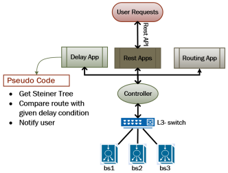
The delay requirement limits the maximum time taken from data sampling at base stations to user designated destination. When a user gives a predefined delay value, FLIP is supposed to find a route for the user that meets the delay requirement. For this we have a RYU application as shown in Fig. 2 dedicated to check this requirement. This application looks at the Steiner tree created for the datapath (see Section V). It compares the delay for path to be taken with user delay requirement and determines if it is possible or not and then notifies the user respectively. The translation module checks the user request and if delay parameter is provided, it invokes the delay application through a REST call.
II-B4 Rate
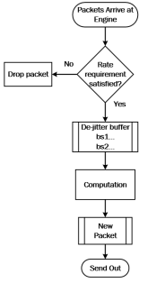
In most IoT scenarios, the sensor data is published either at a fixed rate or at a predefined interval. The rate requirement allows users to select the IoT data collection rate. For example, the base stations are publishing data at the rate of 100ms but the user wants the data to be only received at the rate of 1sec. To achieve this we have added the rate requirement check in FLIP. Fig. 3 shows how the rate requirement can be implemented. As packets arrive at the DPI engine, the rate requirement is checked, and packets are dropped if they do not meet the requirement, otherwise, they are forwarded to the next hop. This is done by the Translation module that configures the DPI engine with the help of engine configuration file (Section III)
II-B5 Jitter
Packet jitter is one of the most important QoS metrics of real time services [13]. In general, Jitter is the variation of delay/latency in arriving packets at the destination. In our framework we consider jitter as difference between sensor data timestamps arriving at a DPI engine for processing. For example the user requires the temperature data of multiple sensors from a base station and this data arrives with jitter at an engine for processing. The DPI engine should check the arrival offset between packets and consider only those packets that meet a certain predefined jitter threshold. For this we maintain a de-jitter buffer (see Fig. 3) at the DPI engine for each incoming port. This buffer value is also controlled through the Translation module and engine configuration file (Section III). The ITU-R has recommended 25 ms jitter as an acceptable value for the delay variation [14]. So FLIP expects a value of from the user if jitter is selected as a requirement.
II-B6 Computation
Computation is the crucial user requirement for our purpose of in-network data processing to reduce IoT data packets dramatically and relieve burdens on the server/cloud side. Computation is the main reason to add DPI engine into the framework. In most IoT scenarios the user is only interested in processed data. In our framework, the DPI engine can read and process L4-L7 data from the incoming packets. For now, FLIP supports basic computation operations such as , , , , , and . Syntax detail on how a user can associate a compute operation with incoming data is explained in Section III.
III Overall Architecture
We describe the overall architecture of our framework to serve user requests for IoT data collection and processing. Our framework is composed of three major modules, Translation module, SDN module, and EPB.
III-A Translation module
. The translation module translates user requests and passes the translated output to FLIP. The translation module is provided to users as a python library. The user can simply import this module into a python script and write requests using the provided syntax (see Section IV). This module communicates with SDN module and EPB via REST APIs. More specifically, it uses python “requests” library. In summary, when a user sends a request in python, the request is translated by this module into multiple REST requests which will then be shared with SDN module and EPB in a distributed manner. This module is also responsible for naming translation for the coverage requirement and datapath selection which is described in detail in Section V.
III-B SDN module
The SDN module consists of:
-
•
RYU SDN controller
-
•
OpenFlow compatible (hardware/software) switches
-
•
RYU applications
-
–
delay application
-
–
ofctl_rest application
-
–
rest_topology application
-
–
routing_ryu application
-
–
Each switch has one or more connected base stations and one EPB . These base stations are assumed to be resourceful nodes that can communicate with common IoT protocols (e.g., MQTT and CoAP). Even though there are many other options for the southbound protocol for communication between a controller and switches, we use OpenFlow, the most prevalent one recently. Regarding the northbound communication between a controller and applications, we use REST APIs.
III-C External Processing Box (EPB)
The EPB consists of:
-
•
Flask web application
-
•
Engine configuration file
-
•
Deep Packet Inspection (DPI) engine
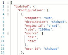
Flask is a lightweight wsgi (web server gateway interface) web application framework [15]. This framework is used to make web server applications that can be accessed through REST APIs. We developed a flask application that provides a REST interface to the Translation module to manage the engine configuration file. The engine configuration file maintains the DPI engine settings for each request. A snippet of engine configuration file is shown in Fig. 4. As shown in the figure, this configuration file is showing the current configuration of engine:e-sw1 for the user: shahzad. It contains compute, source, destination and rate information that will be used by the engine to process the incoming data from source. The DPI engine, written in C language, is the core of EPB. It takes raw packets as input and outputs the processed packets based on the settings provided in the configuration file. This DPI engine in involved in supporting user requirements, i.e., data type, rate, jitter and arithmetic computations. .
III-D How it works
A user sends requests to FLIP using a script like syntax (see Section IV). The request contains the user requirement parameters, and the request is passed to the Translation module. The Translation module converts the user request into appropriate REST requests. These REST requests are then sent to the designated module (SDN, EPB). Next, the Translation module generates the network graph and Steiner tree for datapath selection and installation, which is discussed in Section V.
For example a user wants to collect data from base stations bs1 and bs2 in Fig. 1 and wants to perform operation on the incoming data, he can write a command as below.
This request will establish datapath between , , the DPI engine connected to and . We have used the Networkx Steiner Tree library in FLIP to generate datapath in the network [16]. The request is broken into multiple REST requests. Some of which go to the SDN module and others to the DPI engine. Selection of the DPI engine can be manual as above or automated. We describe the details in Section IV.
For the given example, the SDN module gets the information about the source nodes (bs1, bs2), destination, and selected DPI engine for datapath installation. Switch also receives a REST request to redirect the traffic, which is destined from source nodes to the destination, to the selected engine for computation. The SDN module in association with the translation module serves two major tasks; one is to provide the network detail (i.e., hosts, links, topology, etc.) to the Translation module, and the other is to install a datapath for the given source nodes, switch, DPI engine, and destination. There are three applications running on top of the SDN controller for this.
-
•
OpenFlow control application (ofctl_rest): provides REST APIs for retrieving and updating the switch statistics.
-
•
The topology discovery application (rest_topology): provides REST APIs for discovering hosts, links, and switches in the network.
-
•
Controller basic application (routing_ryu): sends traffic to the controller when there is no table entry for a given flow of traffic. It also complements the rest_topology in the initial discovery of hosts.
For the given example, EPB gets the information about source nodes, destination, and computation (i.e., sum) . This information is passed by the Translation module to the flask web application in the form of REST requests. Next, the flask web application writes this information into the engine configuration file that contains all the configuration for the selected DPI engine. Next, the selected DPI engine reads this configuration file to retrieve its configuration and processes packets accordingly. In this example, DPI engine has to compute on data from source nodes (bs1,bs2).
IV User Command Syntax for Script
FLIP aims at allowing a user to set up the IoT environment in an automated and distributed manner, but there may be a time when the user wants to interact with a particular module, or only some of the configuration needs to be changed. To address such scenarios, we divided the syntax into two categories to make our framework flexible.
-
•
Syntax for automated network setup
-
•
Syntax for manual network setup
The data structure used in FLIP is JSON. So all the requests return data in JSON format which can be utilized in a serialized manner by combining multiple requests together.
IV-A Syntax for automated network setup
With the syntax for automated network setup, a user only has to specify source nodes and requirements and does not have to worry about the engine location or datapath selection. For this, FLIP has the following syntax:
IV-B Syntax for manual network setup
Table I shows the commands for the manual network setup. The commands are categorized into three classes: topology, datapath, and DPI engine. The syntax for manual network setup is as follows.
| Commands | Description | Category |
| getswitches | Get switches information- dpid, port, mac,ip etc. | Topology |
| getlinks | Get links information in the network. | Topology |
| gethosts | Get connected hosts information- mac, ip, switch port etc. | Topology |
| getswdesc | Get switch description for a given dpid e.g. hw_desc, sw_desc, manufacturer etc. | Datapath |
| getflows | Get packes flows information for a given dpid. | Datapath |
| gettables | Get all tables for a given dpid. | Datapath |
| getports | Get all ports information for a given dpid. e.g. received packet, transfered packets, dropped(rx, tx) etc. | Datapath |
| addflow | add a new flow entry for a given dpid. | Datapath |
| modflow | Modify existing flows for a given dpid. | Datapath |
| delflow | delete a specific flow for a given dpid. | Datapath |
| delflowall | delete all flows for a given dpid. | Datapath |
| getconfig | Get configuration details for a given DPI engine. | DPI engine |
| getconfig/user | Get configuration details of user for a given DPI engine. | DPI engine |
| setconfig/user | Set configuration details of user for a given DPI engine. | DPI engine |
| setconfig/user/module | Set configuration details of module of user for a given DPI engine. | DPI engine |
| datapath_m | Get topology info, set datapath and update configuration for given hosts and DPI engine. | All |
IV-C Example
Let’s say the user wants to perform the following operations on the selected base stations in the target network in Fig. 1 in an aggregated manner. Eq. 1 show the desired request in a general syntax.
| (1) |
In Automated syntax case, it can be written like this.
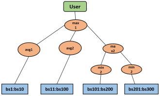
The Translation module builds a task graph (Fig. 6) from this request. This task graph is than mapped to the actual network graph (Fig. 1) to assign DPI engines from the network graph to each operation in the task graph in an automated and distributed manner. Heuristics for this mapping are presented in Section V. Once the heuristics map the operations to DPI engines then a Steiner Tree is created between the Source nodes, DPI engines and destination (user). The task graph has the following components.
-
•
S: Set of base stations (bsxx)
-
•
OP: Operation nodes (max1,avg1,avg2,max2,min1,min2)
-
•
D: Destination node (user)
For the manual syntax case this request can be broken down into a multi-part request as follows:
As we saw in previous example, For each command here, the Steiner tree will be created between source nodes, switch, selected DPI engine and the destination. The difference between automated and manual can be clearly seen. In the automated case, the user did not provide any switch or DPI engine or mapping of operations to switches. while in the manual case, the user provided this detail for each command.
V Flexible IoT datapath installation using REST APIs
In SDN there are two approaches for setting up datapath in the network, proactive approach and reactive approach. While the proactive approach is easy to establish, the reactive approach is more complex and involves multiple dependencies. In this paper we implement proactive approach, referred to as static datapath installation, using an SDN application. For the reactive approach, referred to as dynamic datapath installation, a flexible datapath installation for the IoT is shown using Steiner tree.
V-A Static datapath installation
In this approach all the forwarding devices (switches) are programmed in advance i.e. table entries are populated beforehand to forward traffic between all the connected hosts. This is an efficient method because the traffic to the controller is minimized, saving a lot of overhead. But it becomes inefficient when there are changes made into the network e.g. a link gets down, a host is unreachable etc.
This is referred to as the Static datapath installation in this paper and is achieved by having a controller application populate all the switches as the network is instantiated.
V-B Dynamic datapath installation
This approach is about reacting to changes in the network and maintain connectivity. It may also be the case that the user wants to establish a datapath for a specific hosts or DPI engines as we saw examples in previous sections. So whenever there is a change detected in the network, the controller in notified and a solution is generated on the go. This approach is better suited in conditions where the user wants the network to be able to change or adapt to changes as is common in most IoT use cases.
This is referred to as the dynamic datapath installation in this paper. Our Translation module in association with the SDN module is responsible for the dynamic installation of table entries in the switches according to the user requirements. Whenever a request is made by the user. The Translation module sends an initial request for the topology discovery that is executed by the topology application running on the SDN controller. In reply, the module gets the information about the hosts, links and switches in the network. Using this data combined with the user provided information (Source nodes, destination etc.), the Translation module generates a network graph using python Networkx library. Next, Steiner Tree is created between source nodes, switches, DPI engines and destination.
In case of manual , The Steiner Tree is created with the information provided by the User. While in case of Automated , mapping is performed between task graph (Fig. 6) and the actual network graph (Fig. 1). Following subsection explains the heuristics for the dynamic datapath selection and mapping using Steiner Tree.
Once the path computation is complete. The Translation module starts sending REST requests for the dynamic datapath installation. These requests are received by the ofctl_rest application running on the SDN controller. The user is notified for the successful installation of all the rules in the respective switches. Then the network topology can be displayed using python matlab library.
V-B1 Heuristics to find Steiner tree
In a given network topology, the user may want to establish datapath between a certain number of hosts as shown in examples in the preceding sections. Since the IoT network topologies contain a large number of nodes in general, it is better suited to create a Steiner tree among the desired nodes (source base stations, switches, DPI engines and destination) and establish datapath between them to reduce network resource utilization. The user provides source base stations (), computation information, and destination . We use a heuristic algorithm to find optimal DPI engines for computation and then create a Steiner tree based on Networkx library. This algorithm returns an approximation to the Steiner tree for and with optimally selected switches linked to DPI engines. Algorithm 1 details the applied heuristics.
The input to the Algorithm is - the network topology, - source base stations, destination and - a Tree that shows the task graph representation of user requirements with root , leaf nodes and intermediate nodes as operation nodes. The Output is an approximation of Steiner tree whose weight is within a factor of the weight of the optimal Steiner tree [16]. First the edgenodes are collected. These are the operation nodes that are directly connceted to . Then for each edgenode, a single leafnode is iterated (i.e. one leaf node for each parent edgenode). Also keep in mind that each leafnode . With this leafnode we create a dictionary that is populated by calling the function for each leafnode. The funtion returns the switch id () that is connected to . Eventually the dictionary contains the relations between edgenodes (first level operation nodes) of and the edge switches (directly connected to ) of . Then we move to -parent of iterating in for loop. A loop keeps iterating until . is checked against a list that keeps track of the visited parent nodes. If is not visited, add to the list otherwise break the loop. Then we create another dictionary called that maps each to a in by calling the function. This function returns the adjacent switch in topology for the provided key value i.e. values from the previous dictionary . Then we increment i.e. move to it’s parent node and repeat the process. Once the loop is complete, a list combines and dictionaries. This list now contains the mapped switches in to each operation node in . Now we call the with inputs , , , and .
VI Experimental Evaluation
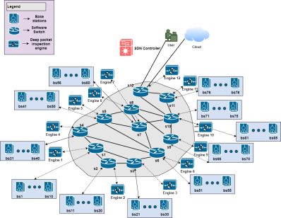
As a proof of concept we tested our framework on mininet which is an emulation environment to build and test network topologies. Mininet provides the option to add software switches and remote controller to support SDN related experiments. We created a partial mesh topology with:
-
•
1 RYU SDN controller
-
•
12 OVS switches
-
•
78 Base stations
-
•
12 DPI engines
-
•
1 Destination (User),
-
•
1 Cloud node
The topology is shown in Fig. 7. The SDN controller connections are omitted in the diagram to maintain clarity.
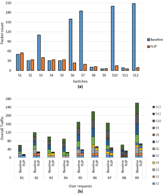
For baseline comparison we have used the same topology without the DPI engines and FLIP intervention i.e. all packets are sent to the user. We send 9 different user requests to this experimental network with and without FLIP’s intervention. We have assumed that without FLIP the request is computed at the destination node. The requests are enumerated below.
We have generated two types of results based on the above requests. In Fig. 8(a) we have compared the packet count on each switch for all the requests collectively. The packets count is obtained by sending REST request to each switch with a flow filter for packets destined to user (destination node). It can be observed that apart from the edge switches (switches directly connected to concerned base stations) the network utilization is reduced because with FLIP enabled, only processed results travel to the user instead of all the packets. In Fig. 8(b) overall network traffic for each request is shown. For each request we compare FLIP with baseline for the overall network utilization. From these results it can be observed that FLIP can reduce the overall network utilization by . This shows that FLIP has the potential to be effectively used in large-scale IoT environments.
VII Related Work
In the past decade, many techniques and frameworks have been proposed to make programming, routing and configuration of IoT systems easy and more efficient. Aggregate programming [17] uses field calculus to program the IoT fabric as a whole such that the basic unit is no longer a single device. WoTT [18] is an application oriented IoT test-bed that focuses on interoperability issues in IoT but it does not support streaming data. PHEME [19] is an analytics re-purposing system that re-purposes Web analytics for IoT data collection. The distinction between our framework and the above is that our framework is SDN based, supports streaming data and has DPI capabilities.
Some other related research works include Fluidware [20], Fibbing [21], Muppet [3]. Fluidware is similar to [17] in terms of programming the IoT devices based on the service and application rather than the device itself but no experimental implementation has been provided. Also it is not SDN based. Fibbing is similar to our framework in some aspects. It has similar script language style, it uses SDN as a base architecture. The difference is that it focuses on combining SDN with Tradition network protocols like IGP and BGP instead of IoT protocols. Muppet is an edge-based multi-protocol architecture for large-scale IoT deployment and service automation. It focuses on the interoperability issue in the IoT and proposes an SDN based (P4) solution to connect heterogeneous devices. While our framework focuses more on the datapath generation for large-scale streaming data and packet processing. Other distinct features of FLIP include:
-
•
Multi user support
-
•
Multi stream support for a given user
-
•
Central Rest Communication
-
•
Multiple engines deployment
-
•
Multiple SDN applications for communication and routing
VIII Conclusion
In this paper, we present FLIP - FLexible IoT Path Programming Framework for large-scale IoT. Moving away from the centralized cloud based IoT automation and processing, FLIP introduces efficient in-network processing of big IoT data that reduces the amount of data arriving at server/cloud. We show through experiments that FLIP has the potential to reduce the bottleneck issues of handling massive IoT data at the server/cloud while meeting various user requirements. Experimental results show that the overall network utilization is reduced by .
References
- [1] Cisco Systems, Inc. Fog Computing and the Internet of Things: Extend the Cloud to Where the Things Are. Cisco press, San Jose, CA, USA, 2016.
- [2] H. I. Kobo, A. M. Abu-Mahfouz, and G. P. Hancke. A survey on software-defined wireless sensor networks: Challenges and design requirements. IEEE Access, 5:1872–1899, 2017.
- [3] M. Uddin, S. Mukherjee, H. Chang, and T. V. Lakshman. Sdn-based multi-protocol edge switching for iot service automation. IEEE Journal on Selected Areas in Communications, 36(12):2775–2786, Dec 2018.
- [4] Feyza Yildirim Okay and Suat Ozdemir. Routing in fog-enabled IoT platforms: A survey and an SDN-based solution. IEEE Internet of Things Journal, 5(6):4871–4889, 2018.
- [5] R. Udechukwu and R. Dutta. Extending openflow for service insertion and payload inspection. In 2014 IEEE 22nd International Conference on Network Protocols, pages 589–595, Oct 2014.
- [6] Zafar Ayyub Qazi, Jeongkeun Lee, Tao Jin, Gowtham Bellala, Manfred Arndt, and Guevara Noubir. Application-awareness in sdn. SIGCOMM Comput. Commun. Rev., 43(4):487–488, August 2013.
- [7] Hesham Mekky, Fang Hao, Sarit Mukherjee, Zhi-Li Zhang, and T.V. Lakshman. Application-aware data plane processing in sdn. In Proceedings of the Third Workshop on Hot Topics in Software Defined Networking, HotSDN ’14, pages 13–18, New York, NY, USA, 2014. ACM.
- [8] Divyashri Bhat, Jason Anderson, Paul Ruth, Michael Zink, and Kate Keahey. Application-based qoe support with p4 and openflow. IEEE Conference on Computer Communications workshops, Jan 2019.
- [9] D. T. Bui and K. Aberkane. A generic interface for open vswitch. In 2016 IEEE NetSoft Conference and Workshops (NetSoft), pages 53–57, June 2016.
- [10] David Hanes. IoT Fundamentals: Networking Technologies, Protocols, and Use Cases for the Internet of Things. Cisco Press, 1 edition edition, 2017.
- [11] Jun Huang, Qiang Duan, Cong-Cong Xing, and Honggang Wang. Topology control for building a large-scale and energy-efficient internet of things. IEEE Wireless Communications, 24(1):67–73, 2017.
- [12] P. A. Laplante, J. Voas, and N. Laplante. Standards for the internet of things: A case study in disaster response. Computer, 49(5):87–90, May 2016.
- [13] B. K. J. Al-Shammari, N. Al-Aboody, and H. S. Al-Raweshidy. Iot traffic management and integration in the qos supported network. IEEE Internet of Things Journal, 5(1):352–370, Feb 2018.
- [14] Syed A. Ahson and Mohammad Ilyas. VoIP Handbook: Applications, Technologies, Reliability, and Security. CRC Press, Inc., Boca Raton, FL, USA, 1st edition, 2008.
- [15] Flask- a lightweight wsgi web application framework. https://palletsprojects.com/p/flask/.
- [16] Networkx- a python package for the creation, manipulation, and study of the structure, dynamics, and functions of complex networks. https://networkx.github.io/documentation/latest/index.html.
- [17] J. Beal, D. Pianini, and M. Viroli. Aggregate programming for the internet of things. Computer, 48(9):22–30, Sep. 2015.
- [18] L. Belli, S. Cirani, L. Davoli, A. Gorrieri, M. Mancin, M. Picone, and G. Ferrari. Design and deployment of an iot application-oriented testbed. Computer, 48(9):32–40, Sep. 2015.
- [19] M. Mikusz, S. Clinch, R. Jones, M. Harding, C. Winstanley, and N. Davies. Repurposing web analytics to support the iot. Computer, 48(9):42–49, Sep. 2015.
- [20] Giancarlo Fortino, Barbara Re, Mirko Viroli, and Franco Zambonelli. Fluidware: An Approach Towards Adaptive and Scalable Programming of the IoT, pages 411–427. Springer International Publishing, Cham, 2019.
- [21] Olivier Tilmans, Stefano Vissicchio, Laurent Vanbever, and Jennifer Rexford. Fibbing in action: On-demand load-balancing for better video delivery. In Proceedings of the 2016 ACM SIGCOMM Conference, SIGCOMM ’16, pages 619–620, New York, NY, USA, 2016. ACM.