*E-mail: mamadou@stsci.edu, †: HiCAT bench Principal Investigator
High-contrast imager for Complex Aperture Telescopes
(HiCAT): 3. first lab results with wavefront control.
Abstract
HiCAT is a high-contrast imaging testbed designed to provide complete solutions in wavefront sensing, control and starlight suppression with complex aperture telescopes. The pupil geometry of such observatories includes primary mirror segmentation, central obstruction, and spider vanes, which make the direct imaging of habitable worlds very challenging. The testbed alignment was completed in the summer of 2014, exceeding specifications with a total wavefront error of 12nm rms over a 18mm pupil. The installation of two deformable mirrors for wavefront control is to be completed in the winter of 2015. In this communication, we report on the first testbed results using a classical Lyot coronagraph. We also present the coronagraph design for HiCAT geometry, based on our recent development of Apodized Pupil Lyot Coronagraph (APLC) with shaped-pupil type optimizations. These new APLC-type solutions using two-dimensional shaped-pupil apodizer render the system quasi-insensitive to jitter and low-order aberrations, while improving the performance in terms of inner working angle, bandpass and contrast over a classical APLC.
keywords:
high angular resolution, coronagraphy, wavefront sensing, wavefront control1 INTRODUCTION
Several space telescopes are currently investigated (e.g. WFIRST-AFTA[1] with monolithic mirror, Large Ultraviolet Optical Infrared [LUVOIR] telescopes with segmented primary mirror, such as ATLAST[2, 3] or HDST[4]) and one of their key goal is the direct imaging and spectroscopy of extrasolar planets, and possibly habitable worlds. However, their aperture geometry makes high-contrast imaging challenging, in particular on two aspects: coronagraphy for starlight suppression and wavefront calibration for contrast stability in the presence of vibrations. We are currently developing HiCAT, a STScI testbed to provide system-level solutions combining wavefront sensing, wavefront control and starlight suppression strategies on such apertures.
Within this framework, we also explore novel high-contrast strategies, including:
-
•
novel pupil remapping techniques (e.g. Active Control of Aperture Discontinuities [ACAD][5]) that use two deformable mirrors (DMs) to re-shape complex pupil (including struts and segment gaps) and offer friendly apertures to coronagraph systems. Recent developments are presented in a companion paper by Mazoyer et al. in these proceedings.
- •
In our previous paper[8], we report on the design overview and the first light results of HiCAT after finalized alignment in the absence of DMs. In this communication, we present our recent developments on HiCAT with the presence of a single facesheet Boston DM and our new findings in coronagraphy for arbitrary apertures.
In Section 2, we present the main features of our testbed. In Section 3, we report on the characterization of our Boston DMs and the integration of a single device in the HiCAT optical train. In Section 4, we present preliminary wavefront control results on the testbed using a single DM and a classical Lyot coronagraph. Finally in Section 5, we show our recent progress in coronagraphy for arbitrary apertures with further implementation in our testbed.
2 HiCAT main features
The testbed optical design was developed using an hybrid approach to define the layout and surface error requirements to minimize amplitude-induced errors, so-called Talbot effects to develop methods for aperture diffraction control. The complete details of our design study are presented in our previous communications[9, 8]. Our testbed uses mirrors with high surface quality (better than ) based on our specifications that are derived from our high-contrast requirements ( contrast floor inside a half-field dark hole produced by a single DM with a perfect coronagraph from 3 to 10 lambda/D with 2% bandpass). The testbed design includes several features:
-
•
a 20 mm pupil mask to mimic the central obstruction and the support struts of the telescope aperture and enable the replication of monolithic telescope geometries such as WFIRST-AFTA.
-
•
three DMs: an Iris AO segmented mirror to mimic segmentation of the telescope primary mirror with 36 segments, similar to ATLAST/HDST, and 2 Boston kilo-DM for wavefront control and pupil remapping techniques such as ACAD[5].
-
•
a starlight suppression system based on the APLC[10] architecture: a reflective apodizer for broadband operations based on the recent developments made by JPL and Princeton[11] and relying on our recent solutions[6], a reflective, focal plane mask (FPM) inherited from the Lyot project[12] and a motorized Lyot stop.
- •
The testbed also have additional room for further implementation of low- and mid-order wavefront sensing concepts such as the Zernike wavefront sensors [15, 16]. Additional feature includes the 4D Fizeau interferometer outside the main optical path for alignment purpose and direct wavefront sensing measurements.
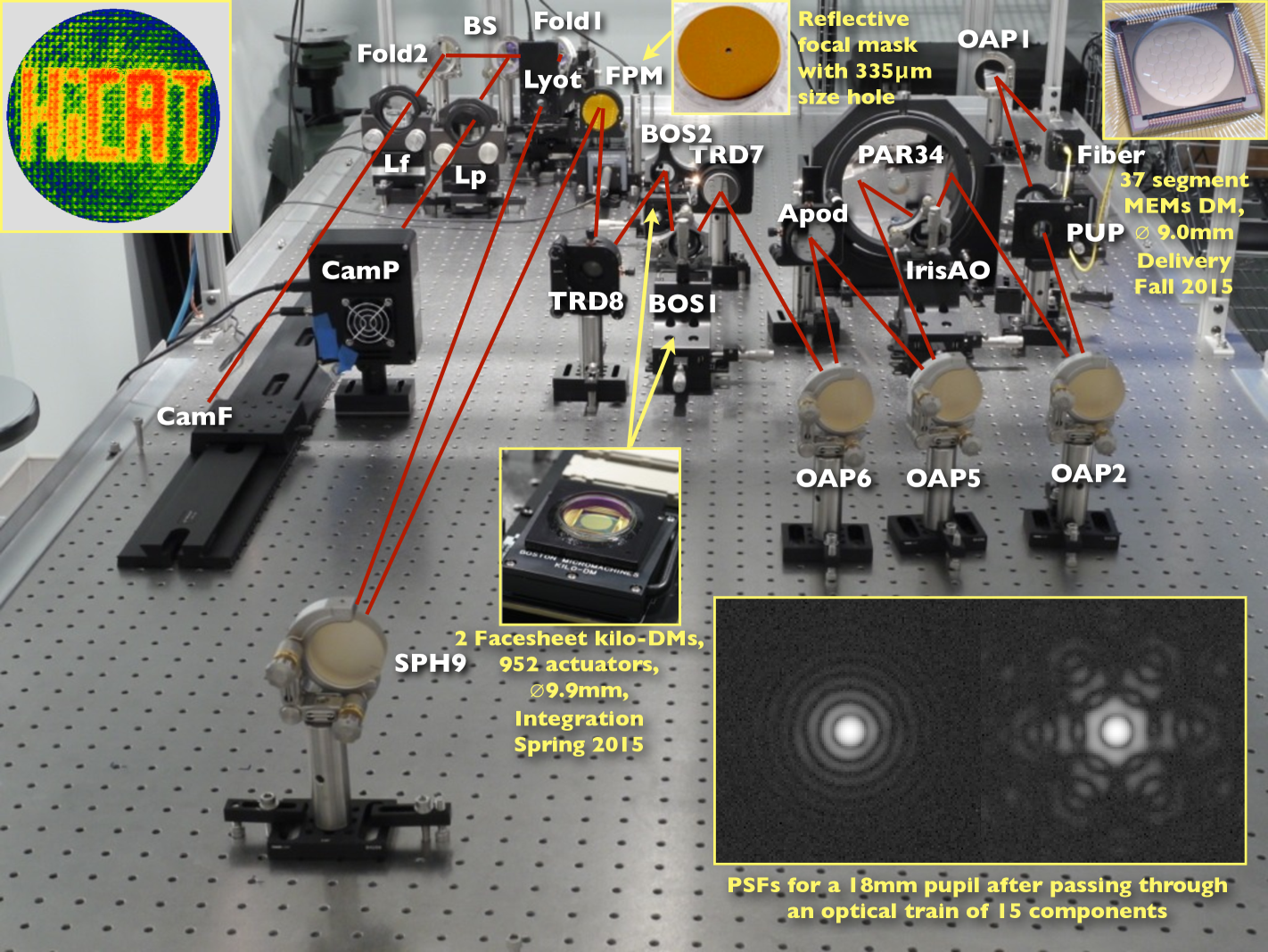
In June 2014, the reflective apodizer and the different DMs were not available yet. They were replaced by flat mirrors with excellent surface error quality (/20 PV surface error over a 2-inch diameter). After procurements of the optical and mechanical parts, we performed the alignment of the testbed and last summer, we obtained our first PSFs in the absence of DMs, see Figure 1. We achieved an optical quality of 12nm rms over a 18mm pupil after passing through an optical train of 15 components. At the end, this testbed will combine a segmented DM to mimic the aperture segmentation, a pupil mask for the central obstruction and spiders of the telescope, two Boston DMs for wavefront control and an APLC for starlight suppression.
3 HiCAT deformable mirrors
3.1 Environment control
During last winter, we received our science grade Boston kilo-DMs for wavefront control and pupil remapping applications with HiCAT. These devices must operate in a clean environment with a relative humidity that remains below 30% for long-term reliability. In particular, humidity is a critical issue since the application of voltage in humid environment leads to corrosion effects on the DM that are irreversible [17, 18].
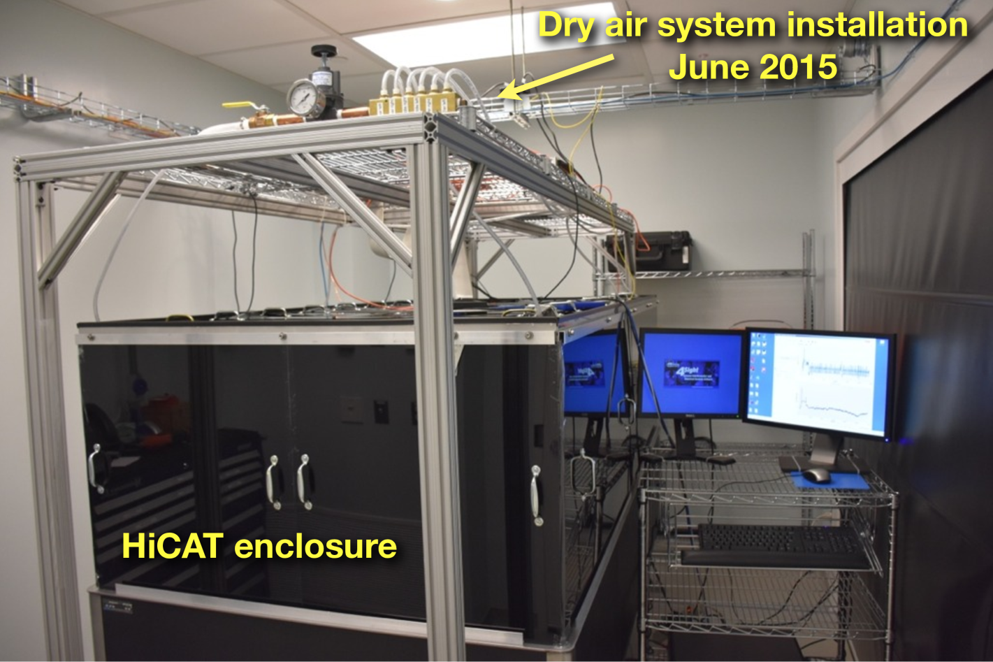
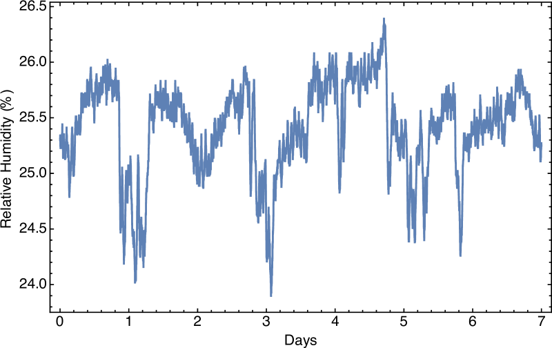
HiCAT is located in the STScI Makidon Optics Lab in a class 1000 clean room with a temperature that is controlled to within 1∘C and relative humidity that remains below 40%. In addition to our lab humidity control, we recently installed a dry air system to our experiment. This system injects 1.5 psi pressure dry air with the output split between 6 lines to different points of the 4 HiCAT enclosure. With this additional system in our testbed, we keep the relative humidity below 30%. In addition, we use temperature and humidity sensors to continuously monitor the environment, ensuring the DM is used only in adequate conditions (see Figure 2).
The dry air system may add unwanted turbulence effects, leading to wavefront variations that makes high-contrast regimes stability challenging. Further plans include the installation of a second stage humidity control within the whole room to keep the humidity below 30% while minimizing the turbulence effects during experiments.
3.2 DM characterization
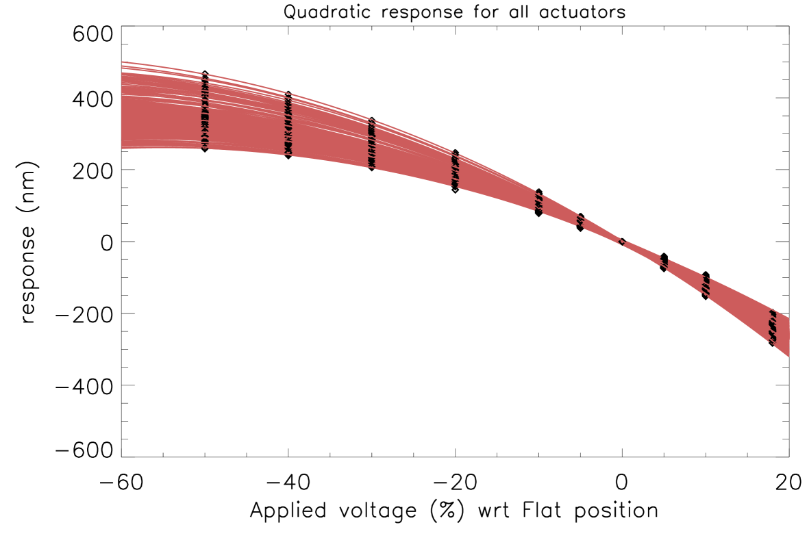
Having a good knowledge of our DM behavior is a key point for further wavefront control operations. To obtain such information, we calibrate our DMs using our 4D Fizeau interferometer in front of it. Based on previous analysis studies[18, 19], we set all the actuators to a DM flat position using a close loop with the 4D Fizeau interferometer. We chose to set this flat position around voltages of 70% of the maximum voltage of the DM to ensure a maximum actuator stroke range during operation. From this reference point, we apply different voltages values from -60% to 20% to every forth actuator across a row and a column. This operation allows us to avoid cross-talk when determining the influence function of each actuators and test all the actuators in just four iterations. Finally, we measure their displacement with the interferometer to determine the actuator influence function.
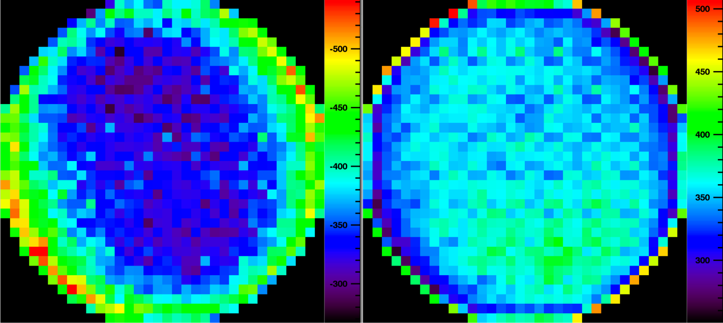
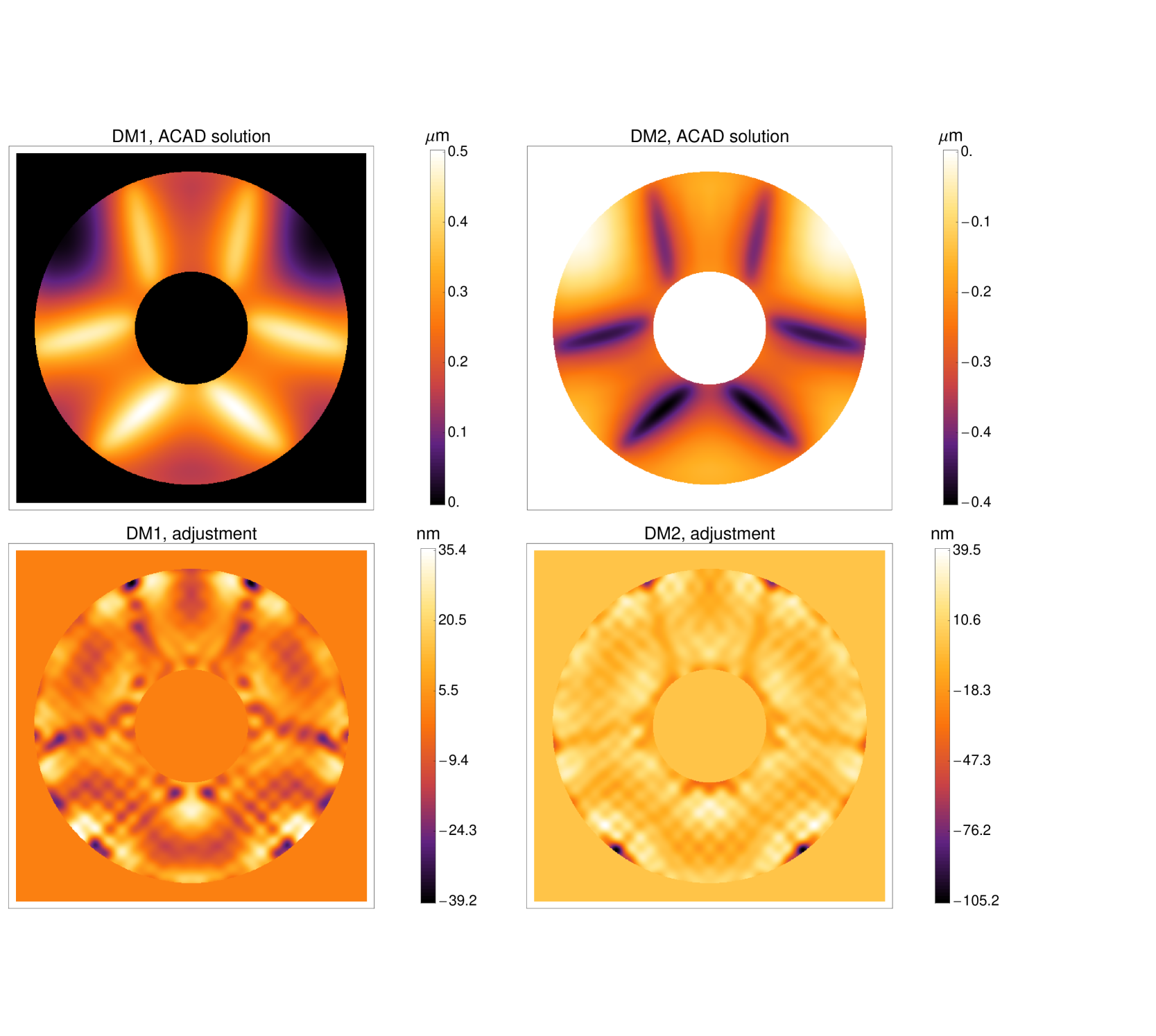
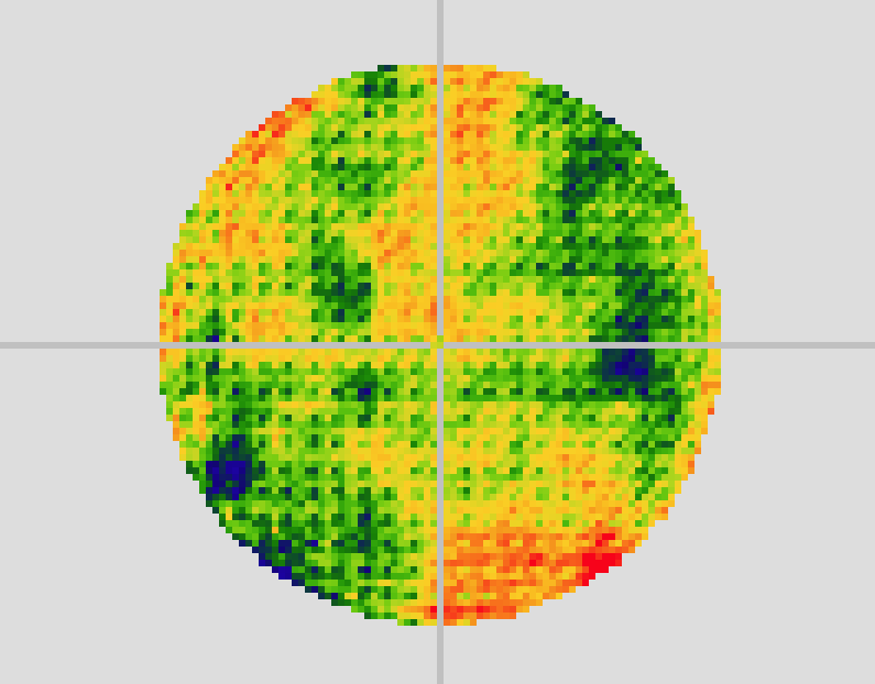
We retrieve a quadratic response curve representing the stroke as a function of the applied voltage for each actuator (see Figure 3, left) and determine the maximum, the minimum and the stroke range of every actuators. On Figure 3 we show for every actuator the maximum values reachable under (center) and above (right) the reference flat position. From this analysis, we deduce that in the worst case, the minimum stroke range for an actuator around the flat position is 632 nm. Mazoyer et al. (submitted)[20] recently made a study on the ACAD applicability on the testbed, considering an WFIRST-AFTA-like pupil, our current DMs characteristics and their separation, see Figure 4. The authors estimated a 470 nm maximum required stroke range to set up the shape of the DMs for application of the pupil remapping technique. This value is well within the measured stroke range for every actuators, confirming the possibility to validate ACAD on HiCAT in laboratory.
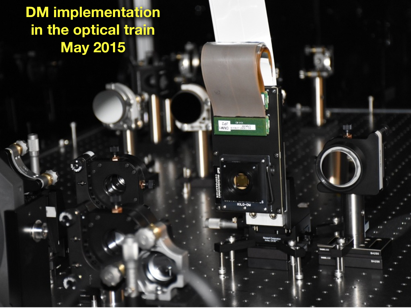
3.3 DM integration
The Boston DMs have two dedicated locations in the HiCAT optical train, the first one in a pupil plane conjugated to the pupil mask and the second one at 30 cm away from the first device in an out-of-pupil plane to perform both phase and amplitude error corrections. The science grade DMs were not available during our alignment in June 2014 and we replaced them by high-quality flat mirror ( PV surface error over a 2-inch diameter part).
After DM characterization, we removed the flat mirror present at the pupil plane location and integrated our first device in Spring 2015. After fine DM positioning, we flattened it and used our interferometer to determine the quality of our alignment. We estimated an optical quality of 13 3 nm rms wavefront error over 18 mm size pupil, see Figure 5. These values with one DM inserted, with no significant loss in terms of wavefront quality, are almost equivalent to our estimates before insertion, confirming the excellent quality of our DM alignment.
We also determine a contribution below 10 nm rms for the low-order aberrations. These small WFE rms values are promising for application of wavefront control algorithms, such as Energy minimization[21], Electric Field Conjugation[22] or Stroke minimization[23]. Before considering such algorithms and as a first step, we started our work on speckle nulling algorithms to check our system.
4 First wavefront control results
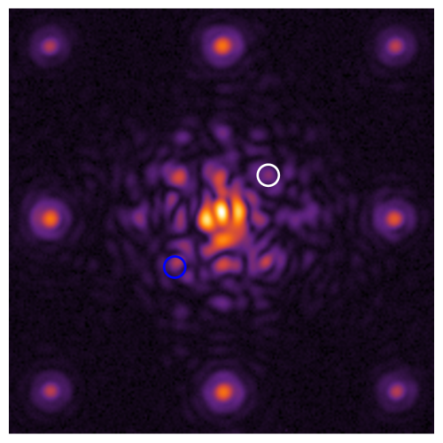
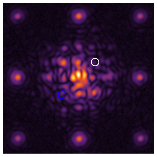
Prior to the 2015 SPIE conference, we started with the implementation of speckle nulling algorithm on HiCAT. Our testbed configuration includes a 18 mm size circular non obstructed pupil, a single Boston DM, a classical Lyot Coronagraph with 335 m size reflective FPM (5.91 relative size for a F/89 beam at nm) and a 10 mm diameter Lyot stop.
We first perform the calibration aspects with our DM in flat position by acquiring coronagraphic images onto CamF. Their analysis allows us to retrieve the plate scale, the optical axis position, the DM orientation and the contrast.
After calibration, we select one speckle and determine the corresponding spatial frequency of the sine wave pattern. We then probe for the speckle phase by first acquiring four images with this sine pattern on the flattened DM with phase shifts of respectively 0, , , . We estimate the speckle intensity for each image to interpolate a sine wave function and we derive the phase shift for the sine wave pattern on the flattened DM that minimizes the speckle intensity. We then determine the speckle amplitude based on its relation with the speckle normalized intensity in the initial image.
We finally combine the flat position with the estimated sine wave pattern on the DM to attenuate the considered speckle. Figure 6 shows the images before and after DM shaping, showing our first single speckle nulling. The fact that the targeted speckle (circled in white) and its symmetric with respect to the main optical axis (circled in blue) are corrected simultaneously underlines the prevalence of phase errors over amplitude errors at these contrast levels and in that specific image location. This wavefront control step is a preliminary result which paves the way for multi-speckle nulling over a one-side dark hole.
However, we do not expect high contrast level in this configuration since we are equipped with a classical Lyot coronagraph. In this context and in view of the future exoplanet direct imaging missions with arbitrary apertures, we have been developing novel designs to push starlight suppression further.
5 Novel coronagraph designs
Coronagraphs design for contrast performance with large segmented aperture is one of the key issue for the direct imaging and spectroscopy of habitable worlds with future large missions. Several approaches have been studied over the past few months to overcome this issue. Our approach addresses the Apodized Pupil Lyot Coronagraph (APLC), a diffraction suppression system that is currently implemented in the recently deployed exoplanet direct imagers P1640, GPI and SPHERE.
The APLC combines a classical Lyot coronagraph with entrance pupil apodization to achieve starlight suppression [24, 25]. For these instruments, the apodization uses a prolate function which is an eigenfunction of the Lyot-style coronagraphic propagation problem for a given mask size. The designs have been optimized considering the contrast as a metric and exploring the parameter space with these prolate functions and the Lyot stop geometry. These solutions are quasi-achromatic and provides a theoretical contrast of at 0.2” in H-band [10, 26]. However, these designs are limited in terms of contrast and IWA.
In this context, we have considered another method to derive novel solutions. This approach is based on shaped pupil type optimization which consists of finding apodizations to produce PSF dark zones. With this method, we increase the number of degrees of freedom with respect to the eigenvalue problem approach: we set the contrast, IWA, bandpass and Lyot stop geometry and we seek for the apodization with the highest throughput that solves the problem.
5.1 Circular axi-symmetric pupils
As a first step, we considered circular axi-symmetric pupils and we found novel solutions that were introduced in N’Diaye et al.[6]. In the context of GPI, we showed our ability to gain one order of magnitude in terms of contrast and 1 /D in IWA[6].
More interestingly, we showed the existence of solutions which produces PSF core smaller than the projected coronagraphic mask. This allows PSF movement within the mask with no impact on the coronagraph performance. Our new concepts are therefore more robust to tip, tilts, focus drifts and other vibrations, a major concern in coronagraphy.
In the context of GPI, we show that our new designs offer a better contrast and a lower sensitivity to low-order aberrations. We also provide contrast designs with an IWA that depends on the bandpass and the central obstruction size, see N’Diaye et al. for further details[6].
5.2 Arbitrary apertures
5.2.1 Solution for large segmented aperture
These proposed solutions essentially apply to circular axi-symmetric apertures, corresponding to a one dimension radial problem. The presence of spiders struts and segment gaps in the pupil will alter the coronagraph performance. This effect can be mitigated with the use of ACAD solutions[5] upstream the diffraction suppression system.
An alternative, complementary approach consists of developing coronagraphic solutions that work with unfriendly pupils. Both Princeton University and STScI teams recently develop novel approaches in the context of WFIRST-AFTA and ATLAST based on APLC and shaped pupil coronagraphs. These approaches extend our previous method for one-dimension radial problem to two-dimension problem. The Princeton team develops the Shaped pupil approach and combines it with a classical Lyot coronagraph to increase the coronagraph performance. At STScI, we consider the APLC and look for apodizers with Shaped pupil solutions. These close paths were studied in parallel in the context of WFIRST by Princeton and in the context of segmented apertures by STScI.
5.2.2 Apodizer manufacturing aspects
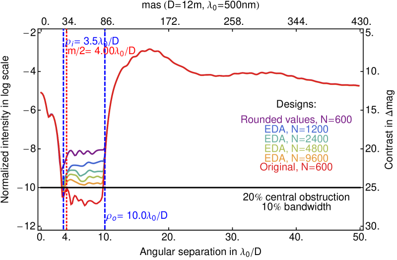
Our solution uses an 600-point diameter across apodization that is not fully binary. Increasing the number of points results in a heavy computational problems that cannot be resolved with our current resources. We consider another approach starting from our current numerical solution. We first test a design with rounded values of our numerical solution. This leads to a contrast loss of two orders of magnitude.
To recover the ultimate contrast, we use an binary approximation which combines a sub-pixellisation of the current solution points and the error diffusion algorithm [27]. With a 16 factor pixellization, we achieved a binary design that almost provides a contrast, see Figure 7.
Based on current technologies for the fabrication of a reflective apodizer, we assume a black silicon pattern mask with 15 m size pixel. A binary mask for our design is feasible with a 144 mm diameter prototype. This is a very encouraging result since our design is manufacturable as-of-today with current technologies and further improvements on size reduction or design are expected to reduce the prototype size.
This concept is furthermore robust to low-order aberrations, providing room for small vibrations of the instrument. Working with large telescope however leads to observation of resolved stars and stellar angular size is a major concern in coronagraphy[28].
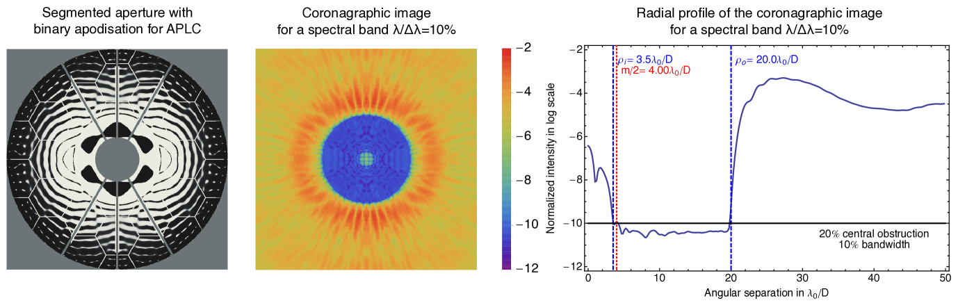
| parameters | value |
|---|---|
| Contrast C | 10 |
| Dark zone inner edge radius | 3.5 |
| Dark zone outer edge radius | 20.0 |
| focal plane mask radius | 4.0 |
| Aperture | 20% central obstruction |
| 1% aperure size spiders | |
| 0.2% aperture size gaps | |
| Lyot stop | 40% central obstrcution |
| 2% aperutre size spiders | |
| no segmentation | |
| Broadband optimization | 3 wavelengths within 10% band |
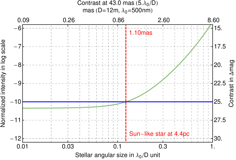
5.2.3 Sensitivity to stellar angular size
We study the impact of stellar leaks on our concept due to stellar angular size. Figure 9 show the contrast at 5 /D as a function of the stellar angular size for a 12 m telescope at 500nm. We can notice a plateau on the contrast curve, showing the stability of our concept to resolved stars. Actually, our concept can observe a Sun-like star beyond 4.4 pc with a 12 m telescope without being impacted by the stellar angular size, proving very encouraging for future direct imaging space missions.
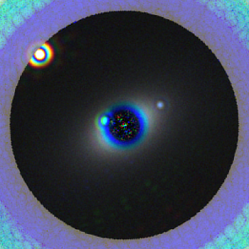
Following these results, we decide to simulate the image of a solar system twin with our concept. We use a model based on spectral and spatial information from Haystack project and based on these assumptions, we produce the image in Figure 10 in which an Earth-like planet can be observed and characterize after 40h exposure time.
6 Conclusions
HiCAT is an operating testbed that enables on-axis monolithic or segmented aperture coronagraph system-level studies. The STScI facility will allow us to develop integrated solutions for unfriendly geometry aperture such as WFIRST-AFTA or HDST. To perform such studies, our testbed will rely on novel diffraction control and wavefront control schemes with multiple DMs (one segmented Iris AO and 2 Boston Micromachines).
This year, we went from the aligned testbed without DMs to preliminary results in wavefront control on testbed with one integrated DM. Our studies include the characterization of Boston DM, its integration in the HiCAT optical train, and the first single speckle nulling with classical Lyot coronagraph.
We have also explored novel coronagraph designs for arbitrary telescope apertures with further implementation in the HiCAT testbed for lab validation. We found designs that provide a contrast at 4 /D with moderate 18% Airy throughput for a large segmented aperture with our hybrid APLC/Shaped Pupil solution, representing a first proof of existence. Our solutions prove quasi-insensitive to low-order aberrations and stellar angular size. In addition, these solutions are manufacturable with as-of-today technologies and are fully functioning.
Our next steps includes the generation of a one side dark hole using speckle nulling algorithm during fall. We will then consider the introduction of the second Boston DM for application of ACAD in laboratory. Based on our recent studies, we will design apodizer prototypes for starlight suppression with different aperture geometries. In the long term, we will have three DMs and we will set novel system level solutions including diffraction suppression and wavefront control for high-contrast generation and stability with arbitrary apertures, advancing technologies for direct imaging and spectroscopy of habitable worlds with future space missions.
Acknowledgements.
This work is supported by the National Aeronautics and Space Administration under Grants NNX12AG05G and NNX14AD33G issued through the Astrophysics Research and Analysis (APRA) program (PI: R. Soummer). This material is also partially based upon work carried out under subcontract 1496556 with the Jet Propulsion Laboratory funded by NASA and administered by the California Institute of Technology. The authors warmly acknowledge Tyler Groff, N. Jeremy Kasdin, Charles-Philippe Lajoie, Bruce Macintosh, Dimitri Mawet, Colin Norman, J. K. Wallace, and Stuart Shaklan for fruitful discussions during the testbed design. The authors are also very grateful to STScI and its staff members, in particular Bill Franz, Joe Hunkeler and Kelly Coleman, for their invaluable support.References
- [1] D. Spergel, N. Gehrels, C. Baltay, D. Bennett, J. Breckinridge, M. Donahue, A. Dressler, B. S. Gaudi, T. Greene, O. Guyon, C. Hirata, J. Kalirai, N. J. Kasdin, B. Macintosh, W. Moos, S. Perlmutter, M. Postman, B. Rauscher, J. Rhodes, Y. Wang, D. Weinberg, D. Benford, M. Hudson, W.-S. Jeong, Y. Mellier, W. Traub, T. Yamada, P. Capak, J. Colbert, D. Masters, M. Penny, D. Savransky, D. Stern, N. Zimmerman, R. Barry, L. Bartusek, K. Carpenter, E. Cheng, D. Content, F. Dekens, R. Demers, K. Grady, C. Jackson, G. Kuan, J. Kruk, M. Melton, B. Nemati, B. Parvin, I. Poberezhskiy, C. Peddie, J. Ruffa, J. K. Wallace, A. Whipple, E. Wollack, and F. Zhao, “Wide-Field InfrarRed Survey Telescope-Astrophysics Focused Telescope Assets WFIRST-AFTA 2015 Report,” ArXiv e-prints , Mar. 2015.
- [2] M. Postman, T. Brown, K. Sembach, M. Giavalisco, W. Traub, K. Stapelfeldt, D. Calzetti, W. Oegerle, R. Michael Rich, H. Phillip Stahl, J. Tumlinson, M. Mountain, R. Soummer, and T. Hyde, “Advanced Technology Large-Aperture Space Telescope: science drivers and technology developments,” Optical Engineering 51, p. 011007, Jan. 2012.
- [3] L. D. Feinberg, A. Jones, G. Mosier, N. Rioux, D. Redding, and M. Kienlen, “A cost-effective and serviceable ATLAST 9.2m telescope architecture,” in Society of Photo-Optical Instrumentation Engineers (SPIE) Conference Series, 9143, p. 16, Aug. 2014.
- [4] J. Dalcanton, S. Seager, S. Aigrain, S. Battel, N. Brandt, C. Conroy, L. Feinberg, S. Gezari, O. Guyon, W. Harris, C. Hirata, J. Mather, M. Postman, D. Redding, D. Schiminovich, H. P. Stahl, and J. Tumlinson, “From Cosmic Birth to Living Earths: The Future of UVOIR Space Astronomy,” ArXiv e-prints , July 2015.
- [5] L. Pueyo and C. Norman, “High-contrast Imaging with an Arbitrary Aperture: Active Compensation of Aperture Discontinuities,” Astrophysical Journal 769, p. 102, June 2013.
- [6] M. N’Diaye, L. Pueyo, and R. Soummer, “Apodized Pupil Lyot Coronagraphs for Arbitrary Apertures. IV. Reduced Inner Working Angle and Increased Robustness to Low-order Aberrations,” Astrophysical Journal 799, p. 225, Feb. 2015.
- [7] M. N’Diaye, E. Choquet, A. Carlotti, L. Pueyo, S. Egron, L. Leboulleux, O. Levecq, M. D. Perrin, J. K. Wallace, C. Long, R. Lajoie, C.-P. Lajoie, A. J. Eldorado Riggs, N. T. Zimmerman, T. D. Groff, N. J. Kasdin, R. J. Vanderbei, D. Mawet, B. Macintosh, S. Shaklan, and R. Soummer, “High-contrast imager for Complex Aperture Telescopes (HiCAT): APLC/shaped-pupil hybrid coronagraph designs,” in American Astronomical Society Meeting Abstracts, 225, p. 258.09, Jan. 2015.
- [8] M. N’Diaye, E. Choquet, S. Egron, L. Pueyo, L. Leboulleux, O. Levecq, M. D. Perrin, E. Elliot, J. K. Wallace, E. Hugot, M. Marcos, M. Ferrari, C. A. Long, R. Anderson, A. DiFelice, and R. Soummer, “High-contrast Imager for Complex Aperture Telescopes (HICAT): II. Design overview and first light results,” in SPIE, 9143, p. 27, Aug. 2014.
- [9] M. N’Diaye, E. Choquet, L. Pueyo, E. Elliot, M. Perrin, J. Wallace, T. Groff, A. Carlotti, D. Mawet, M. Sheckells, S. Shaklan, B. Macintosh, N. J. Kasdin, and R. Soummer, “High-contrast imager for Complex Aperture Telescopes (HiCAT): 1. Testbed design,” in SPIE, 8864, Sept. 2013.
- [10] R. Soummer, “Apodized Pupil Lyot Coronagraphs for Arbitrary Telescope Apertures,” Astrophysical Journal, Letters 618, pp. L161–L164, Jan. 2005.
- [11] K. Balasubramanian, D. Wilson, V. White, R. Muller, M. Dickie, K. Yee, R. Ruiz, S. Shaklan, E. Cady, B. Kern, R. Belikov, O. Guyon, and N. J. Kasdin, “High contrast internal and external coronagraph masks produced by various techniques,” in Society of Photo-Optical Instrumentation Engineers (SPIE) Conference Series, 8864, p. 1, Sept. 2013.
- [12] B. R. Oppenheimer, A. P. Digby, L. Newburgh, D. Brenner, M. Shara, J. Mey, C. Mandeville, R. B. Makidon, A. Sivaramakrishnan, R. Soummer, J. R. Graham, P. Kalas, M. D. Perrin, L. C. Roberts, Jr., J. R. Kuhn, K. Whitman, and J. P. Lloyd, “The Lyot project: toward exoplanet imaging and spectroscopy,” in Advancements in Adaptive Optics. Edited by Domenico B. Calia, Brent L. Ellerbroek, and Roberto Ragazzoni. Proceedings of the SPIE, Volume 5490, pp. 433-442 (2004)., D. Bonaccini Calia, B. L. Ellerbroek, and R. Ragazzoni, eds., Presented at the Society of Photo-Optical Instrumentation Engineers (SPIE) Conference 5490, pp. 433–442, Oct. 2004.
- [13] B. H. Dean and C. W. Bowers, “Diversity selection for phase-diverse phase retrieval,” Journal of the Optical Society of America A 20, pp. 1490–1504, Aug. 2003.
- [14] J.-F. Sauvage, L. Mugnier, B. Paul, and R. Villecroze, “Coronagraphic phase diversity: a simple focal plane sensor for high-contrast imaging,” Optics Letters 37, p. 4808, Dec. 2012.
- [15] J. K. Wallace, S. Rao, R. M. Jensen-Clem, and G. Serabyn, “Phase-shifting Zernike interferometer wavefront sensor,” in Society of Photo-Optical Instrumentation Engineers (SPIE) Conference Series, 8126, Sept. 2011.
- [16] M. N’Diaye, K. Dohlen, T. Fusco, and B. Paul, “Calibration of quasi-static aberrations in exoplanet direct-imaging instruments with a Zernike phase-mask sensor,” Astron. & Astrophys. 555, p. A94, July 2013.
- [17] H. R. Shea, A. Gasparyan, H. B. Chan, S. Arney, R. E. Frahm, D. López, S. Jin, and R. P. McConnell, “Effects of electrical leakage currents on mems reliability and performance,” Device and Materials Reliability, IEEE Transactions on 4(2), pp. 198–207, 2004.
- [18] K. M. Morzinski, A. P. Norton, J. W. Evans, L. Reza, S. A. Severson, D. Dillon, M. Reinig, D. T. Gavel, S. Cornelissen, B. A. Macintosh, and C. E. Max, “MEMS practice: from the lab to the telescope,” in Society of Photo-Optical Instrumentation Engineers (SPIE) Conference Series, 8253, p. 4, Mar. 2012.
- [19] J. Mazoyer, R. Galicher, P. Baudoz, P. Lanzoni, F. Zamkotsian, and G. Rousset, “Deformable mirror interferometric analysis for the direct imagery of exoplanets,” in Proc. SPIE, Society of Photo-Optical Instrumentation Engineers (SPIE) Conference Series 9148, p. 914846, Jul 2014.
- [20] J. Mazoyer, P. Pueyo, C. Norman, M. N’Diaye, R. P. van der Marel, and R. Soummer, “Active compensation of aperture discontinuities for WFIRST-AFTA: analytical and numerical comparison of propagation methods and preliminary results with an AFTA like pupil.,” subm. in JATIS .
- [21] P. J. Bordé and W. A. Traub, “High-Contrast Imaging from Space: Speckle Nulling in a Low-Aberration Regime,” Astrophysical Journal 638, pp. 488–498, Feb. 2006.
- [22] A. Give’on, B. Kern, S. Shaklan, D. C. Moody, and L. Pueyo, “Broadband wavefront correction algorithm for high-contrast imaging systems,” in Society of Photo-Optical Instrumentation Engineers (SPIE) Conference Series, 6691, p. 0, Sept. 2007.
- [23] L. Pueyo, J. Kay, N. J. Kasdin, T. Groff, M. McElwain, A. Give’on, and R. Belikov, “Optimal dark hole generation via two deformable mirrors with stroke minimization,” Appl. Opt. 48, pp. 6296–6312, Nov 2009.
- [24] C. Aime, R. Soummer, and A. Ferrari, “Total coronagraphic extinction of rectangular apertures using linear prolate apodizations,” Astron. & Astrophys. 389, pp. 334–344, July 2002.
- [25] R. Soummer, C. Aime, and P. E. Falloon, “Stellar coronagraphy with prolate apodized circular apertures,” Astron. & Astrophys. 397, pp. 1161–1172, Jan. 2003.
- [26] R. Soummer, A. Sivaramakrishnan, L. Pueyo, B. Macintosh, and B. R. Oppenheimer, “Apodized Pupil Lyot Coronagraphs for Arbitrary Apertures. III. Quasi-achromatic Solutions,” Astrophysical Journal 729, pp. 144–+, Mar. 2011.
- [27] C. Dorrer and J. D. Zuegel, “Design and analysis of binary beam shapers using error diffusion,” Journal of the Optical Society of America B Optical Physics 24, pp. 1268–1275, June 2007.
- [28] O. Guyon, E. A. Pluzhnik, M. J. Kuchner, B. Collins, and S. T. Ridgway, “Theoretical Limits on Extrasolar Terrestrial Planet Detection with Coronagraphs,” Astrophysical Journal, Supplement 167, pp. 81–99, Nov. 2006.