Efficient Animation of Sparse Voxel Octrees
for Real-Time Ray Tracing
Abstract
A considerable limitation of employing sparse voxels octrees (SVOs) as a model format for ray tracing has been that the octree data structure is inherently static. Due to traversal algorithms’ dependence on the strict hierarchical structure of octrees, it has been challenging to achieve real-time performance of SVO model animation in ray tracing since the octree data structure would typically have to be regenerated every frame. Presented in this article is a novel method for animation of models specified on the SVO format. The method distinguishes itself by permitting model transformations such as rotation, translation, and anisotropic scaling, while preserving the hierarchical structure of SVO models so that they may be efficiently traversed. Due to its modest memory footprint and straightforward arithmetic operations, the method is well-suited for implementation in hardware. A software ray tracing implementation of animated SVO models demonstrates real-time performance on current-generation desktop GPUs, and shows that the animation method does not substantially slow down the rendering procedure compared to rendering static SVOs.
Index Terms:
Voxel, octree, animation, ray tracing, computer graphics.1 Introduction
The overarching goal of computer graphics is to use a computer to deterministically render images based on a specification of some form. These images may be stored for later consumption, or they may be presented in real-time on a display as part of a graphics pipeline. In the last decades, rasterisation has emerged as the most popular technique for rendering real-time computer graphics. However, recent developments have shown that ray tracing may be a legitimate alternative to rasterisation for certain real-time rendering applications [1]. There are indications of a new paradigm being established in computer graphics, the central tenet of which is that ray tracing may be used in conjunction with traditional rasterisation rendering, so that each technique is utilised towards its strengths. Nvidia demonstrated this in the autumn of 2018 with their introduction of a new range of consumer graphics processing units (GPUs) containing dedicated hardware for acceleration of ray tracing [2].
A common application of ray tracing is the rendering of three-dimensional volumetric models. The sparse voxel octree (SVO) is a specific flavour of the octree data structure that may be used to store such volumetric model data. SVOs are especially attractive for ray tracing since they have been studied thoroughly, resulting in a vast body of published research on their optimised traversal as part of a ray tracing pipeline. Hence, if a three-dimensional object can be adequately represented by an SVO model, it may be rendered efficiently and with sufficient visual fidelity through ray tracing. The structure of an SVO closely resembles that of the traditional sparse octree, but differs in that instead of using the data structure to subdivide space or sort objects, the octree itself directly encodes the volumetric data. Certain properties are associated with the tree nodes, which enable the data structure to natively describe arbitrary objects as sets of voxels. The model fidelity is consequently limited only by the hierarchical depth of the octree. The challenge of using SVOs for real-time computer graphics is that efficient animation is hindered by their strict hierarchical structure. In an arbitrary animation sequence, each node of the octree may be altered, which would typically require that the tree structure be regenerated every frame.
The purpose of this research is to derive a new method that efficiently facilitates the animation of otherwise static SVO models. The method supports a certain subset of animation transformations which will collectively be referred to as rigid-body animation. As defined in this work, rigid-body animation comprises all transformations that do not alter the internal data of the model. This means, in turn, that any transformation that is to be applied to the model must be applied equally to all the model’s internal vertices, and that during the animation sequence, the relative positions and orientations of all nodes will remain unchanged in model space.
In addition to the animation method itself—which will be introduced in Section 3—a set of optimisation techniques will be presented and discussed in Section 4. These techniques are included since they are relevant for future use of the animation method, and will generally benefit an implementation in terms of performance. They were employed to great success in the authors’ own software implementation, which will be evaluated alongside the animation method in Section 5.
2 Related Works
No general technique for animation of SVO models optimised for ray tracing was found in the literature. Nonetheless, a single attempt was found for a special-case form of animation of SVO models. [3] introduces a method for SVO animation based on the idea that each leaf node of the tree is an individual atom that may be animated. However, the method is not applicable for ray tracing. As is explicitly stated by the work’s author, Dennis Bautembach, the hierarchical structure of the SVO model is destroyed as part of the animation process. Consequently, most ray tracing algorithms will no longer work, since efficient intersection tests are effectively prohibited. Bautembach therefore resorts to rasterisation in order to render the animated sparse voxel octrees. Thus, to the best of the authors’ knowledge, the method presented in this article is the only efficient technique for the animation of SVOs for use in ray tracing to date.
2.1 SVO Traversal Algorithms
Any implementation of the animation method introduced in this article will as a matter of necessity have to employ an algorithm for the traversal of sparse voxel octree models in order to fully facilitate the underlying ray tracing procedure. The animation method is generally agnostic as to the underlying traversal algorithm, but a brief introduction to the field is appropriate, and will be presented in the following.
The earliest method found in the literature for octree traversal along a ray was authored by Andrew Glassner in 1984 [4]. The paper reports that over 95 percent of the total rendering time may be spent on ray-object intersection calculations. Hence, there is a huge potential for performance gain by optimising this process. Glassner then suggests sorting objects in the scene into an octree and presents an algorithm for traversal of such an octree. Another method was introduced by Marc Levoy in 1990 [5]. In the paper, he introduces two different methods for enhancing the performance of volumetric data ray tracing. The first of his methods is relevant in that octrees are employed to encode spatial coherence in the data.
A number of subsequent attempts at improving the performance of octree traversal exist. They can generally be grouped into two main categories based on how they solve the traversal problem: bottom-up and top-down schemes [6]. The algorithm by Glassner, as well as other, similar schemes are instances of bottom-up octree traversal algorithms [7, 8]. The method by Levoy, and a host of other algorithms [6, 9, 10, 11, 12, 13, 14, 15] provide examples of a top-down parametric traversal algorithms. From the number of publications alone, it appears that top-down traversal algorithms are most popular in the research field.
An efficient algorithm for octree traversal was presented by Revelles, Ureña, and Lastra in 2000 [6]. They introduce a top-down parametric method that is very well documented. The algorithm is presented as recursive, but due to its simplicity has been shown to translate well into an iterative method, which is desirable for parallelisation [16]. After [6] was published, there seems to be few new algorithms that contest its speed and simplicity. An algorithm based on the work by [12] was introduced in 2006 by [14] (and subsequently improved upon by the same authors [15]) which may be more efficient in some circumstances. However, in addition to not being as well-documented as [6], the algorithm is recursive and according to [17] does not readily translate to an efficient implementation on a GPU or in hardware.
2.2 Parallelising the Workload
The algorithms discussed in the previous section are sequential, single-threaded algorithms which do not deliberately exploit the highly parallelisable nature of ray tracing. In order to achieve real-time performance, the software implementation developed as part of this work is parallelised and accelerated using a GPU by means of the Nvidia CUDA API. It is therefore relevant to briefly review works that discuss advantages of using the parallel computing capabilities of GPUs to distribute the workload.
In 2009, [18] proposed a new approach for rendering large volumetric data sets by ray tracing on a GPU. The result is a system which achieves interactive to real-time performance while rendering several billion voxels. The method takes care to avoid using a stack—and therefore no recursion—in order to increase GPU optimisation. Mipmapping is utilised as a LoD-technique in order to hide visual noise. The algorithm supports on-the-fly loading of data chunks from CPU memory to GPU memory whenever the ray tracer encounters missing data, which means that model size is not bounded by GPU memory.
Laine and Karras [17] use the Nvidia CUDA API to exploit the general-purpose capabilities of GPUs to efficiently trace static SVO models in parallel. Alongside their ray tracer implementation, a compact SVO memory structure is introduced. A simplified variant of this memory structure is employed in the authors’ software implementation.
Gobbetti and Marton [19] demonstrate the rendering of very large surface models using out-of-core data management, meaning that the approach supports data sets too large to fit in working memory. In their paper, they use hardware acceleration in the form of a GPU to parallelise the workload of rendering the data sets, while natively supporting different levels of detail. A similar method could perhaps be utilised in ray tracing hardware to support very large, highly detailed models.
2.3 Other Works of Significance
As part of his master’s thesis, the corresponding author of this article worked towards a hardware implementation of an SVO ray tracer with support for animation. Knowing that the animation method would be presented in this article at a later stage, Espe [20] treated the method as previous work in his thesis. In his work, he focused on the implementation of the SVO traversal algorithm before considering animation, and time constraints lead to the animation of SVO models in hardware never being fully functional. As such, a hardware implementation of the method to be presented in this article is still an open problem.
Another work of interest is [16], in which a hardware ray tracer for static SVO models is implemented. The choice of algorithms closely match the algorithms selected for the software implementation this article, and the feasibility of a hardware implementation of these is demonstrated.
3 The Method
Rigid-body animation can be achieved by modelling the scene as a system of rigid bodies transformed relative to each other. Each individual body in this system may be regarded as a static model with an associated transform that varies with time. The models that make up the scene can be static models of any kind, for instance SVO models. This means that rigid-body animation in SVO ray tracing may be achieved by simply treating the scene as a set of independent SVOs, in which each SVO is a static model with a corresponding transform. The process of animation is accordingly reduced to modifying these transforms in a timely manner. The internal data of each SVO may remain unmodified for the duration of the animation.
The question naturally raised at this stage is how the associated transforms could be applied to SVO models, and what significance this would have for the SVO traversal algorithm. Although it would be the traditional approach for polygonal models, it is not feasible to apply the transformation to every data point contained in an SVO model during the rendering stage. This has been shown in [3] to destroy the hierarchical structure of the SVO, and thus prohibit efficient traversal.
The novel approach presented here is to simply invert the problem. Instead of transforming the model data during or after traversal, one may perform an inverse transformation on the ray before traversal begins. In other words, each ray in the ray tracing process will be transformed from world space to the local co-ordinate system of the animated SVOs that are to be traced. The process is illustrated by Fig. 1, in which a ray is shown entering the boundaries of two SVO models with different transforms. As the figure highlights, the ray itself is transformed inversely in order to facilitate animation of the models.
3.1 Mathematical Formulation
If the animation method is to be implemented in software or hardware, a mathematical formulation for the ray transformation is necessary. For this purpose, a ray is defined parametrically as
| (1) |
where is the ray origin and is the ray direction. A ray on this form will in the following be denoted by the arrow symbol. Given the definition in Eq. 1, a transformation from the ray in world co-ordinates to the ray in the SVO’s local co-ordinates must be derived. The desired transformation should behave as shown in Eq. 2.
| (2) |
A graphical representation of the desired transformation is shown in Fig. 2. By initially only allowing the SVO to be rotated and translated, the mathematical derivation becomes straightforward. The transformation is affine and results in a translation and rotation of the ray, which means that formulating mathematically is simply a matter of deriving two matrices with which to multiply the constituent vectors and of the ray . Given the rotation matrix and the translation matrix of the SVO, the transformation function can be formulated as described in the following. Since it makes no sense translating a directional vector, it should be self-evident that the ray direction may only be influenced by the rotation of the SVO. The ray origin, however, is affected by both rotation and translation.
The resulting definition of is shown in Eq. 3. The ray direction is determined by simply premultiplying it with the inverse rotation of the SVO. The ray origin is initially translated so that the origin of its co-ordinate system is at the origin of the octree. Then the vector is rotated around the SVO origin by the same inverse rotation as employed for the ray direction.
| (3) | ||||
Note that the inverse of translation and rotation matrices are quite simple to attain in both software and hardware. The inverse of a translation matrix is computed by negating its co-ordinates, and the inverse of a rotation matrix is its transpose.
3.2 Extending the Method to Allow Anisotropic Scaling
The transformation so far only accounts for translation and rotation of SVO models. Whereas these two affine transforms are the only ones strictly required to provide the functionality of rigid-body animation, animation of model size is often crucial element of many animation sequences.
The most convenient way of supporting scaling in the scheme which has been presented is to implement the support at the traversal stage of the ray tracing process. Fortunately, many SVO traversal algorithms are designed to allow the tuning of octree dimensions. By employing this directly in the animation process, the method presented above may remain simple, and only take the rotation and translation into account. As an example, in the traversal algorithm presented in [6], the dimensions of the octree are defined initially as a set of algorithm parameters. This approach does, however, make the support for anisotropic scaling dependent on the choice of traversal algorithm.
4 Optimisations
A number measures may be taken in order to further improve the efficiency of the method. The most effective optimisations explored in the authors’ software implementation will be discussed in the following as a supplement to the animation technique.
4.1 Bounding-Sphere Tests
As a result of the sheer number of intersection tests, the most computationally heavy stage of the ray tracing process is the traversal of the SVO [4]. It is therefore desirable to solely traverse SVOs that can potentially lead to a ray hit. For instance, consider a situation where the origin of the ray is outside the bounds of the SVO model, and the the ray points in the opposite direction to that of the octree. In such circumstances, the SVO can safely be eliminated from the process, as it is impossible for the ray to ever hit it.
There are many criteria one may use to determine which octrees that will never be hit by a given ray, some more efficient in implementation than others. A method that will be explored in the following is to perform an intersection test between the ray and the bounding sphere of the SVO. This intersection test is fast and can be solved analytically. An explicit form of the equation to be evaluated is presented in Eq. 4, where and are defined as earlier and the point is the centre of the sphere. If the resulting value of is real and less than the sphere radius, the ray intersects the sphere.
| (4) |
The rationale behind choosing a bounding sphere instead of a bounding box to represent the bounds of an octree model is that the bounding sphere is invariant under rotation of the corresponding SVO. The only properties to consider when constructing the sphere is the position of its centre and its radius, both of which are readily obtainable from the SVO; indeed, they are given directly by its translation and scale. This means that the ray-sphere intersection test remains simple even though the underlying SVO may have an arbitrary orientation. A drawback of using bounding spheres instead of bounding boxes is that it will on occasion lead to false positives. Situations may arise where an octree model is processed and traversed even though the ray does not intersect with the SVO.
In Fig. 3 the principle is illustrated. A scene consisting of four animated SVOs is shown, where bounding spheres are utilised to determine which octree models that will be missed by the ray. In this case, only SVOB will be traversed, as the bounding sphere of the other three octrees in the scene do not intersect the ray.
4.2 Depth Sorting
The use of bounding spheres also lends itself to another optimisation which will be elaborated in the following. The general idea is that SVO models may be traced in a front-to-back order, sorted by the distance along the ray for each intersected bounding sphere. Once traversal of an SVO model results in a ray hit that is closer than the bounding sphere of the next SVO to be traced, the ray tracing process may be stopped early, as no subsequent object can lie in front of the current hit.
An example of the depth sorting technique is illustrated in Fig. 4, where a scene consisting of four animated SVOs is shown. The tracing is performed in a sorted manner, the order of traversal determined by the distance to the bounding sphere centre. In this example the order of increasing depth will be . The figure shows a situation where SVOD is traversed without a hit, SVOB is traversed as a false positive, SVOA results in a trace hit, and SVOC is not traversed. The ray tracing process is terminated after the third SVO model since it results in a ray hit, and the distance along the ray of this hit is closer than the distance to the boundary of the next octree that would be traversed. In other words, it is mathematically impossible that traversal of SVOC will yield a ray hit closer than the hit produced by traversal of the third octree.
4.3 Hit Buffer Algorithm
A simple buffering mechanism was developed as part of the work. The buffer—termed hit buffer object (HBO)—stores the ray tracing result for each pixel in the last rendered frame. The idea is that if, for a given pixel, the scene is unchanged enough since the last frame, the traversal of SVOs for this pixel may be streamlined, or even skipped, in which case the value from the last frame is reused. The algorithm is illustrated as a flow chart in Fig. 5.
Stored for each pixel in the HBO data structure are: the colour, the normal, the -value of the hit along the ray (i.e. the depth, which means that the HBO also functions as a depth buffer), a unique identifier of the SVO that was hit, and the nature of the hit. The last field provides information for the hit buffer algorithm, such as whether nothing was hit, or whether the ray passed through a single or multiple bounding spheres before arriving at the hit point.
The HBO is used in conjunction with a set of state variables to determine if the value of a pixel is unchanged between frames. Each SVO in the scene, as well as the camera, has a flag that specifies if the object has moved since the last frame (if it is dirty). The application can then look up the hit buffer data for the current pixel and, if both the camera and the SVO object hit by the ray the last frame are unchanged, simply use the last value and avoid tracing the SVO again. It is also required that the ray did not pass through multiple bounding spheres before the hit for this optimisation to take place. The reason for this requirement is that if the ray passes through other SVOs, these might have changed in the meantime, and there is no way of determining if the ray would hit data in these SVOs without traversing them again.
5 Evaluation
A software demonstration of the method was prepared for this article. The implementation was written in the C programming language and employs the APIs Nvidia CUDA and OpenGL—the former for parallelising the ray tracing process, and the latter for easing the process of displaying the result. Three different GPUs were available for testing: the Nvidia Quadro T1000 [21], the Nvidia GeForce GTX 680 [22], and the Nvidia Quadro P5000 [23]. The most relevant specifications for these are listed in Table I.
| GPU name | Type | Year | CUDA cores | Base freq. |
|---|---|---|---|---|
| Quadro T1000 | Mobile | 1395 MHz | ||
| GeForce GTX 680 | Desktop | 1006 MHz | ||
| Quadro P5000 | Desktop | 1164 MHz |
In addition to the animation method and the optimisations presented in this article, the software implementation employs the work of [6] and [17]. In [6], an efficient method for octree traversal is described. This traversal algorithm was chosen since it is simple and fast, and also improves upon the performance of earlier algorithms. Other, more efficient algorithms exist (such as [14]), but since the focus of this article is to showcase an animation method, greater emphasis is placed on the simplicity of the algorithm rather than its pure speed and efficiency. Introduced by [17] is a data structure scheme for storing SVO data. A simplified version of this structure was used for the SVO models in the authors’ implementation.
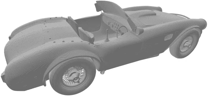
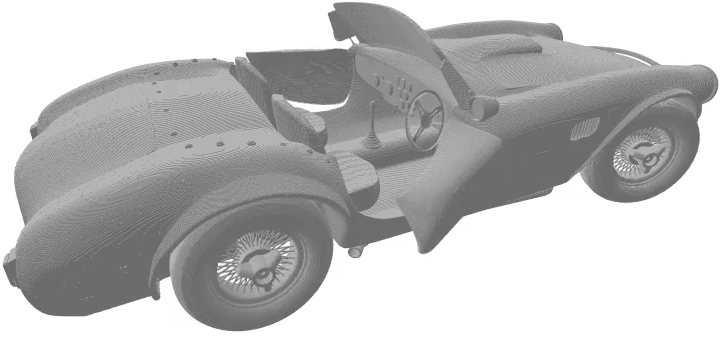
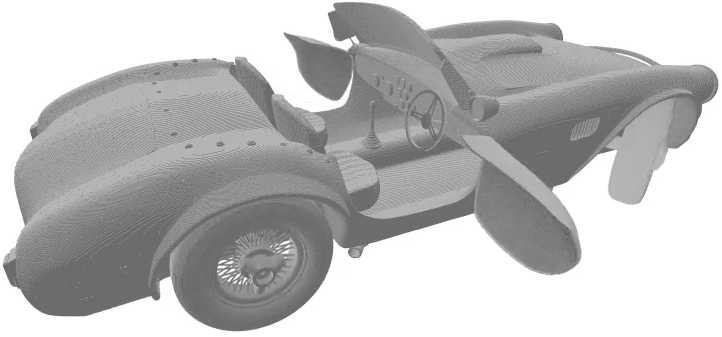
The software implementation was employed to render an animated model of a car, illustrated by snapshots in Fig. 6. The source model was obtained from [24], and further processed in two steps to create the SVO models. First, a raw voxel model was generated by rasterising the .obj polygonal model using the Binvox program [25]. Secondly, a custom program was developed in order to reduce the raw voxel model to an SVO model on the format introduced by [17]. The result was an SVO data structure with an hierarchical depth of 11, and a total of data points. In order to establish a comparative basis, both static and animated versions of the scene were rendered. In the animated scene, the car body, the wheels, the doors, and the steering wheel are each realised as separate SVO models.
5.1 Performance
Shown in Fig. 7 are the average render times and frame rates for three different scenes rendered with the different GPUs of the test setup. Running at a resolution of , the implementation gathered data over 60 seconds for each test case. The first scene featured a static model of a car realised as a single SVO model analogous to the first snapshot shown in Fig. 6a. Since animation was not enabled for the model, the situation illustrates the performance of a pure implementation of the SVO traversal algorithm, without any of the overhead associated with animation. The second scene contained an animated car with each part of the body realised as separate SVOs. It represents an implementation of the solution proposed in this article without any of the optimisation techniques introduced in Section 4. The third scene is the animated scene rendered with the bounding sphere optimisation techniques and the hit buffer mechanism enabled.
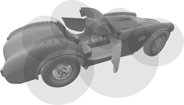
The last two scenes were visually identical and resulted in the animation sequence shown in Fig. 6. All three scenes were traced with a static camera to ensure that the circumstances of the tests were equal and that the performance could be compared. In addition, if a dynamic camera were to be used the hit buffer algorithm enabled for the last scene would be rendered ineffective. The bounding spheres used as part of the optimisation techniques are shown highlighted in Fig. 8 for illustrative purposes.
At which point application performance can be classified as real-time is not well-defined. Nonetheless, it can be argued in good faith that the performance of the P5000 must clearly be classified as real-time computer graphics, as a frame rate of is higher the refresh rate of most common computer monitors. It is therefore shown that the animation method can deliver real-time performance on current generation GPUs. For the T1000 GPU, the difference in raw performance between the static model and the animated model with optimisations enabled is quite small—the decrease in frame rate is . However, in the case of the GTX 680 and P5000 GPUs, the frame rate increases by and , respectively. These numbers indicate that most of the execution time is spent in the traversal section of the software, not as a part of the animation process itself. In addition, it seems that the optimisations may be more effective at higher frame rates, and will in some situations improve upon the performance of the underlying SVO traversal algorithm. The results lend credence to the claim that the method is suitable for real-time animation of SVO data. Moreover, since the animation technique does not introduce a noticeable overhead, it is expected that further improvements in performance may be achievable with even more optimisation in the traversal algorithm itself.
It should be noted that the results presented are gathered from a single animated model. It is therefore not completely certain that the data fully represent the general case. As part of future work, it would be advantageous to run the implementation across a wide spectrum of different models and situations in order to gather more data. This could be used to further investigate the claim that the animation does not tax the performance noticeably, and help gain understanding of how the method and optimisations responds to the rendering of different data sets.
5.2 Memory Requirements
In terms of memory, the proposed solution does not represent a significant increase in space, as only a few more bytes are required per SVO in order to enable animation. Whereas a typical SVO model may be several megabytes in size (the SVO for the car body shown in Fig. 6 has a size of ), a homogeneous transform matrix only requires when using 32-bit floating-point numbers. As for memory bandwidth, the proposed solution should perform very well. This is because the only data that need to be updated between frames are the transform matrices, and in some cases the bounding spheres and scales.
Even though each octree in theory only needs a single transform matrix to specify its translation, rotation, and scale, it might be beneficial to store the bounding sphere and scale separately in order to speed up execution.
5.3 Suitability for Hardware Implementation
The animation method itself is agnostic with regard to the underlying traversal algorithm and the SVO data structure. Nonetheless, the algorithms chosen for the software implementation have already been demonstrated to work in hardware [16, 20]. The animation logic itself is iterative and consists almost exclusively of matrix multiplication which can readily be pipelined and accelerated by dedicated circuits. The optimisations should also be relatively straightforward to translate into hardware. The hit buffer algorithm will require memory and simple Boolean logic, whereas the most complex part of the ray-sphere intersection test will be a square root hardware module, as shown in Eq. 4. Since a hardware implementation will be relatively simple, a consequence is that the computations may be kept on-chip, allowing shorter critical paths, and a higher core frequency.
In the discussion of memory requirements, the conclusion was drawn that the proposed solution should not be limited by memory bandwidth since a very small amount of data has to be updated in memory between frames. This also translates well into direct improvements in a hardware setting. By limiting the memory bandwidth, a hardware implementation may avoid performing accesses to external memory altogether, further increasing performance. In addition, since the sparse voxel octree data remain unchanged when animated, one or more levels of caching may be employed in order to reduce the latency associated with memory accesses. Lastly, the amount of data that describes the animation of an octree is very small, which means that these transformation matrices may be stored directly in very fast registers close to the core, further reducing memory access latency.
5.4 Limitations
The main limitation of the animation method is that it only supports rigid-body animation, which will limit its applications. Effects such as deformation, bending, and other features which are often needed to enable complex and life-like animations are not supported. Consequently, the animation functionality provided by the solution is mostly suited for stiff, mechanical objects.
There may also be issues with the method’s scalability, since each part of the scene that is to be animated is required to be stored as a separate SVO with an associated transform. A complex object with hundreds of moving parts would have to be formulated as hundreds of independent SVOs, and every ray would have to be intersection-tested with the bounding sphere of each SVO in the scene. Future work may include exploring measures that can be taken to mitigate problems stemming from these predicted scalability issues. An idea to this end is to sort the entire scene into a larger octree so that only relevant SVOs would have to be considered by the ray tracing algorithm.
5.4.1 Limitations of the Optimisation Techniques
There is a limit to the region of applicability for most optimisation techniques. The hit buffer optimisation is limited in that becomes ineffective once the camera moves. This is a consequence of the fact that once the camera is altered in some fashion, virtually all rays have also necessarily changed since the last frame. As such, the previous results stored in the hit buffer are no longer applicable, and the entire scene must be retraced.
The bounding sphere optimisation techniques are still effective regardless of camera movement, as they are optimisations in world space, not in screen space. In other words, these optimisations are amendments to the ray tracing algorithm itself, and not dependent on the camera, and thus should provide a performance gain regardless of camera movement.
6 Conclusion
In this article, a method for animation of SVO models was introduced. The method circumvents the need to rebuild the octree structure for each frame of an animation sequence, and is therefore suited for real-time computer animation. Being relatively simple to implement in software, the method is agnostic in regards to the underlying octree traversal algorithm. It facilitates rigid-body animation, meaning that rotation and translation of SVO models are supported. Anisotropic scaling is in many cases also possible, depending on the choice of traversal algorithm.
Using a set of optimisation techniques, it was shown that the general performance of the animation method may be enhanced. Initially, bounding spheres were introduced as a means to determine whether SVO models could be preemptively excluded from the rendering process. It was also demonstrated that these bounding spheres may be utilised for depth sorting, so that the object in the scene can be traversed in the most efficient order possible. Lastly, a buffering mechanism termed the hit buffer algorithm was presented, which takes advantage of certain situations where parts of the scene are unchanged to reduce the required processing load.
A software implementation of the animation method was introduced to permit a direct performance comparison between the rendering of static and animated SVO models. The software implementation was tested using three available GPUs on consumer hardware, with results testifying that the rendering of an animated model with optimisations enabled generally outperforms its static counterpart. The software implementation demonstrates real-time performance while rendering animated SVO models on a desktop computer, with the strongest GPU reporting an average frame rate of about —a frame rate higher the refresh rate of most common computer monitors.
The method is well-suited for implementation in hardware; since the method is relatively simple, it should not pose serious implementation challenges beyond those associated with a hardware implementation of the traversal algorithm itself. On account of real-time performance already being demonstrated when running the method in software, it is expected that an implementation in application-specific hardware would be able to deliver real-time performance of more complex models and scenes, and at larger resolutions. It will be interesting to follow any further developments, as it has been predicted that ray tracing may very well play a central role in the future of real-time computer graphics [1]. A hardware implementation of the method is certainly something that could be explored as part of future work, perhaps building on related works such as [16] or [20].
References
- [1] B. Caulfield. (2018, Mar.) What’s the Difference Between Ray Tracing and Rasterization? [Online]. Available: https://blogs.nvidia.com/blog/2018/03/19/whats-difference-between-ray-tracing-rasterization/
- [2] NVIDIA Corporation. (2018) GeForce RTX - Graphics Reinvented. [Online]. Available: https://www.nvidia.com/en-us/geforce/20-series/
- [3] D. Bautembach, “Animated Sparse Voxel Octrees,” Bachelor’s thesis, Dept. of Inform., Univ. of Hamburg, Hamburg, Germany, 2011.
- [4] A. Glassner, “Space subdivision for Fast Ray Tracing,” IEEE Comput. Graph. Appl., vol. 4, no. 10, pp. 15–24, Oct. 1984.
- [5] M. Levoy, “Efficient Ray Tracing of Volume Data,” ACM Trans. on Graph., vol. 9, no. 3, pp. 245–261, Jul. 1990.
- [6] J. Revelles, C. Ureña, and M. Lastra, “An Efficient Parametric Algorithm for Octree Traversal,” J. of WSCG, vol. 8, no. 1–3, pp. 212–219, May 2000.
- [7] H. Samet, “Implementing Ray Tracing with Octrees and Neighbor Finding,” Comput. & Graph., vol. 13, no. 4, pp. 445–460, Jan. 1989.
- [8] ——, Applications of Spatial Data Structures: Computer Graphics, Image Processing, and GIS. Boston, MA, USA: Addison-Wesley, 1990, pp. 85–97.
- [9] M. Agate, R. L. Grimsdale, and P. F. Lister, “The HERO Algorithm for Ray-Tracing Octrees,” in Proc. of the 4th Eurographics Conf. on Advances in Comput. Graph. Hardware (EGGH’89), Hamburg, Germany, 1989, pp. 61–73.
- [10] F. W. Jansen, “Data Structures for Ray Tracing,” in Proc. of Data Struct. for Raster Graph., Steensel, The Netherlands, 1985, pp. 57–73.
- [11] D. Cohen and A. Shaked, “Photo-Realistic Imaging of Digital Terrains,” Comput. Graph. Forum, vol. 12, no. 3, pp. 363–373, Aug. 1993.
- [12] I. Gargantini and H. H. Atkinson, “Ray Tracing an Octree: Numerical Evaluation of the First Intersection,” Comput. Graph. Forum, vol. 12, no. 4, pp. 199–210, Oct. 1993.
- [13] R. Endl and M. Sommer, “Classification of Ray-Generators in Uniform Subdivisions and Octrees for Ray Tracing,” Comput. Graph. Forum, vol. 13, no. 1, pp. 3–19, Feb. 1994.
- [14] A. Knoll, I. Wald, S. Parker, and C. Hansen, “Interactive Isosurface Ray Tracing of Large Octree Volumes,” in IEEE Symp. on Interactive Ray Tracing, Salt Lake City, UT, USA, 2006, pp. 115–124.
- [15] A. Knoll, I. Wald, and C. Hansen, “Coherent Multiresolution Isosurface Ray Tracing,” The Vis. Comput., vol. 25, no. 3, pp. 209–225, Mar. 2009.
- [16] A. Wilhelmsen, “Efficient Ray Tracing of Sparse Voxel Octrees on an FPGA,” Master’s thesis, Dept. of Electron. and Telecommun., Norwegian Univ. of Sci. and Technol., Trondheim, Norway, 2012.
- [17] S. Laine and T. Karras, “Efficient Sparse Voxel Octrees,” IEEE Trans. Vis. Comput. Graphics, vol. 17, no. 8, pp. 1048–1059, Aug. 2011.
- [18] C. Crassin, F. Neyret, S. Lefebvre, and E. Eisemann, “Gigavoxels: Ray-Guided Streaming for Efficient and Detailed Voxel Rendering,” in Proc. of the 2009 Symp. on Interactive 3D Graph. and Games (I3D’09), Boston, MA, USA, 2009, pp. 15–22.
- [19] E. Gobbetti and F. Marton, “Far Voxels – A Multiresolution Framework for Interactive Rendering of Huge Complex 3D Models on Commodity Graphics Platforms,” ACM Trans. on Graph., vol. 24, no. 3, pp. 878–885, Jul. 2005.
- [20] A. E. Espe, “Real-Time Ray Tracing of Animated Sparse Voxel Octrees on FPGA,” Master’s thesis, Dept. of Eng. Cybern., Norwegian Univ. of Sci. and Technol., Trondheim, Norway, 2019.
- [21] NVIDIA Corporation. (2019) Quadro for Mobile Workstations. [Online]. Available: https://www.nvidia.com/content/dam/en-zz/Solutions/design-visualization/documents/quadro-rtx-mobile-line-card-us-nvidia-r7-web.pdf
- [22] ——. (2012) GeForce GTX 680. [Online]. Available: https://www.geforce.com/hardware/desktop-gpus/geforce-gtx-680
- [23] ——. (2016) Data Sheet: Quadro P5000. [Online]. Available: https://images.nvidia.com/content/pdf/quadro/data-sheets/192195-DS-NV-Quadro-P5000-US-12Sept-NV-FNL-WEB.pdf
- [24] alex38. (2016) AC Cobra 269 3D model. Free3D. [Online]. Available: https://free3d.com/3d-model/ac-cobra-269-83668.html
- [25] P. Min, “Binvox 3D Mesh Voxelizer.” [Online]. Available: https://www.patrickmin.com/binvox/
![[Uncaptioned image]](/html/1911.06001/assets/x1.png) |
Asbjørn Engmark Espe is a PhD candidate at the Department of Engineering Cybernetics, Norwegian University of Science and Technology (NTNU). His research interests include low-power and low-maintenance embedded systems, ray tracing, and wireless sensor networks. Espe received his MS degree in cybernetics and robotics from NTNU in 2019. He is a Student Member of the IEEE. Contact him at asbjorn.e.espe@ntnu.no. |
![[Uncaptioned image]](/html/1911.06001/assets/ogjermundnes_bw.png) |
Øystein Gjermundnes is an associate professor at the Department of Electronic Systems, Norwegian University of Science and Technology (NTNU). His research interests include hardware design and verification. Gjermundnes received his MS degree in microelectronics from NTNU in 2002, and his PhD degree from NTNU in 2006. Contact him at oystein.gjermundnes@ntnu.no. |
![[Uncaptioned image]](/html/1911.06001/assets/shendseth_bw.png) |
Sverre Hendseth is an associate professor at the Department of Engineering Cybernetics, Norwegian University of Science and Technology (NTNU). His research interests include real-time systems, programming languages, and software engineering. Hendseth received his MS degree in engineering cybernetics from the Norwegian Institute of Technology (NTH) in 1987, and his Dr.Ing. degree from NTH in 1994. He is a Member of the IEEE. Contact him at sverre.hendseth@ntnu.no. |