The Interaction of Galling and Oxidation in 316L Stainless Steel
Abstract
The galling behaviour of 316L stainless steel was investigated in both the unoxidised and oxidised states, after exposure in simulated PWR water for . Galling testing was performed according to ASTM G196 in ambient conditions. 316L was found to gall by the wedge growth and flow mechanism in both conditions. This resulted in folds ahead of the prow and adhesive junction, forming a heavily sheared multilayered prow. The galling trough was seen to have failed through successive shear failure during wedge flow. Immediately beneath the surface a highly sheared nanocrystalline layer was seen, termed the tribologically affected zone (TAZ). It was observed that strain-induced martensite formed within the TAZ. Galling damage was quantified using Rt (maximum height - maximum depth) and galling area (the proportion of the sample which is considered galled), and it was shown that both damage measures decreased significantly on the oxidised samples. At an applied normal stress of the galled area was vs. and the Rt was vs. for the unoxidised and oxidised sample respectively. This trend was present at higher applied normal stresses, although less prominent. This difference in galling behaviour is likely to be a result of a reduction in adhesion in the case of the oxidised surface.
1 Introduction
Cobalt-based hardfacing alloys are used in nuclear applications on account of their high wear and galling resistance. Under the ALARA (as low as reasonably achievable) principle [1], cobalt must be removed from nuclear applications. Cobalt is not used in the reactor pressure vessel (RPV) and so components do not undergo direct irradiation. However, after extended use, components wear, with wear debris travelling into the RPV, becoming irradiated and transmutating from 59Co to 60Co, which is a gamma radiation source. Since the wear debris will continue to travel around the primary circuit, it may cause additional doses to personnel working on and around the primary circuit, including during shutdowns. As such, alternative Co-free materials are desired for tribologically sensitive components such as valve seats.
Austenitic stainless steels containing hard particles have been suggested for some time as replacement materials for the StelliteTM family of alloys (Co-Cr-W with W- and Cr-carbides), which are currently the most widely used cobalt alloys used in nuclear applications. In both cases, the alloy matrix is fcc austenite, with the ability to form strain-induced martensite (hcp -martensite in StelliteTM and bct -martensite in austenitic stainless steels). A number of galling resistant stainless steel alloys have been developed over the past four decades which incorporate martensite formation during wear [2, 3, 4, 5, 6, 7]. However, none have been considered suitable for wide-scale use in reactors, owing to their reduced galling resistance at elevated temperature, such as those seen in light water reactors. Further work is therefore necessary to develop a stainless steel which is galling resistant at elevated temperatures.
Galling is an adhesive wear mechanism, active at slow sliding speeds and relatively high compressive stresses. It is reported to cause gross plastic deformation of mated surfaces, particularly when their movement is bound [8].
A number of works have investigated the mechanisms of galling and their relation to surface deformation. Some concluded that adhesion and galling occurs primarily through the agglomeration of wear particles and that these heavily work-hardened particles adhere to one surface and gouge the opposing surface [9, 10, 11, 12]. Other works have concluded that galling appears to occur through the adhesion of opposing asperities which shear to failure, and may also result in the formation of peaks and troughs [13, 14]. Through this mechanism, layering of material has been observed to occur, resulting in the formation of the peaks and the formation of ‘lips’ in subsequently formed troughs [15, 16, 17].
Although work has predominantly been focussed upon the mechanism of surface deformation and failure, some work has also been carried out on the sub-surface changes observed after adhesive wear and galling. A number of authors have reported the formation of a heavily sheared sub-surface region [18, 8] which, for austenitic stainless steels has been found to contain strain-induced -martensite (SIM) [18, 19]. As such, martensite is widely considered to be a source of galling resistance in stainless steels since the reduction in galling resistance correlates with the reduction in SIM formation at elevated temperatures [19]. This heavily sheared region is similar in appearance to the sub-surface microstructural changes observed after fretting, termed the white layer [20, 21].
Much of the work on galling in the literature has been concerned with the qualification of galling, with little work being produced on the quantification of galling. Examples of this include the ASTM G98 and G196 galling tests which state whether a sample has or has not galled at a given load, in order to find a threshold galling load, ASTM G98 [22], or the proportion of samples which gall at a given load (galling frequency), ASTM G196 [23]. Budinski and Budinski sought to improve the recording of results for these tests by introducing a scoring system, corresponding to the type of damage seen e.g. burnishing, adhesive transfer and incipient galling, however, these results are not strictly speaking quantitative [24]. Ives et al. significantly developed the quantification of galling, using the average maximum peak-to-valley height, root-mean-square of Rt, displaced volume and damage aspect ratio to quantify a single galled sample [25].
An area of research which has not been widely explored is the galling behaviour of an oxidised metal substrate, despite observations which suggest significant improvement of galling resistance in simulated light water reactor conditions [19]. This knowledge gap is addressed in this work.
Many galling resistant stainless steels were developed from a base composition of 316 or 304 stainless steel, with the addition of large volume fractions of hard phases (carbides, nitrides or silicides). Here, 316L stainless steel is used to investigate the galling behaviour of a stainless steel matrix material in both the bare-metal and oxidised states, without the complication of ceramic hard phase additions.
2 Method
316L bar, supplied by Goodfellow, was manufactured into ASTM G196 specimens with Rt = (maximum height - maximum depth), and machined with the surface lay circumferential.
An autoclave was used to produce a representative PWR environment, enabling a representative oxide to be formed on galling specimens before testing. 316L stainless steels were oxidised at for in a static autoclave, with a water pressure of . The water chemistry was controlled to contain 2 ppm Li, which was added as LiOH,10.5 pH, 4 ppm dissolved and less than 5 ppb of .
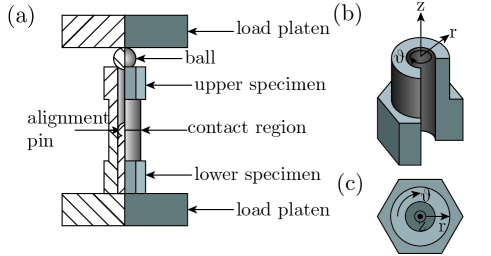
An ASTM G196 rig, Figure 1, was used to perform the galling tests. All tests were self-mated, in either the oxidised or unoxidised state, and performed at ambient temperature and pressure. A torque of was applied using a torque wrench, taking approximately to complete a single revolution. The normal stress was applied using a hydraulic loading cylinder, controlled to – (the lower limit of the equipment, and a representative contact stress for gate valves in nuclear power plant, respectively [26]). If a test pair seized, the test was finished when seizure occurred. If seizing occurred, the adhesive junction was broken before the mating surfaces could be observed.
Before testing, the mating surfaces were cleaned using propanol. After testing, surfaces were left undisturbed.
A Veeco white light interferometer and an Olympus OLS5000 LEXT confocal microscope were used to detect surface topography and generate sample surface reconstructions.
Post-processing was employed to remove surface artefacts, sample edges and to generate data which was missing due to a lack of light detection. Linear interpolation of nearest neighbours was used to remove sample artefacts and reconstruct the full sample surface. In addition, surfaces were translated such that the minimally worn and ungalled regions were considered flat and at the zero plane ( in height).
A number of galling measures developed and used by Ives et al. will be used in this work; the maximum height, depth and Rt. In addition to these, the galled area was calculated, where the galled area is the proportion of the sample which is either above or below a threshold height value, corresponding to the initial surface Rt.
Samples were prepared for metallographic examination by grinding through to 4000 grit SiC paper, using a diamond suspension as a first polishing stage, and a final polishing stage using an OPU suspension. Imaging was then produced using Zeiss Sigma 300 and Auriga SEM’s in both secondary (SE) and backscattered electron (BSE) modes. XFlash 6160 and Oxford Instruments X-Max detectors in the Sigma and Auriga SEM’s were also used for imaging and X-ray microanalysis.
In addition, a FEI Helios Ga FIB/SEM was used to perform site-specific in-situ lift outs for observation in a JEOL 2100Plus TEM. The TEM also contained STEM and STEM-EDX capabilities, which were used in conjunction with a Panalytical X’pert Pro diffraction (XRD) system in order to investigate oxide chemistries and structures and the fine sub-surface microstructural features seen as a result of galling.
Phase identification was performed using the JEOL 2100 Plus TEM in diffraction mode and a Panalytical X’pert Pro diffraction (XRD) system.
3 Results & Discussion
3.1 Oxide Characterisation
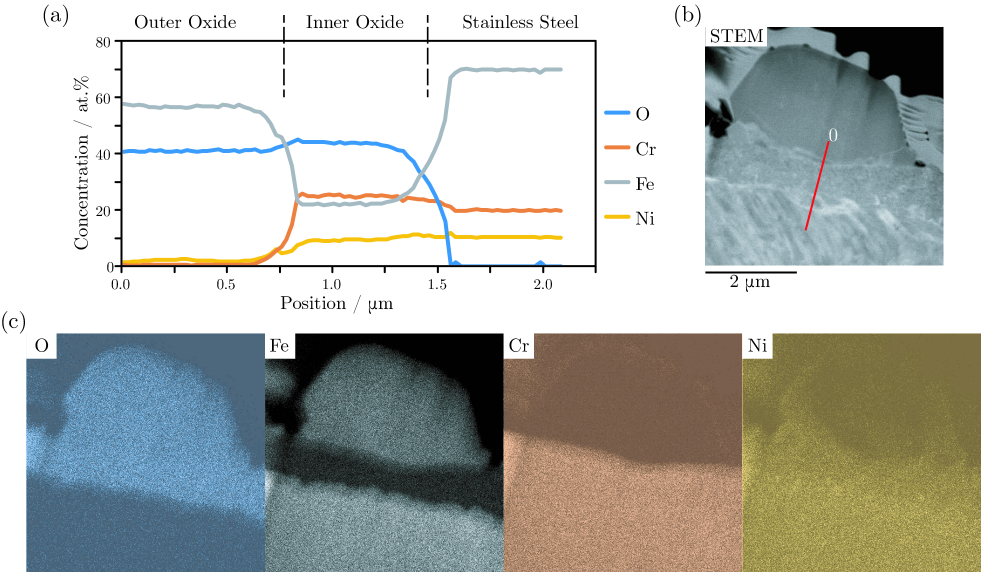
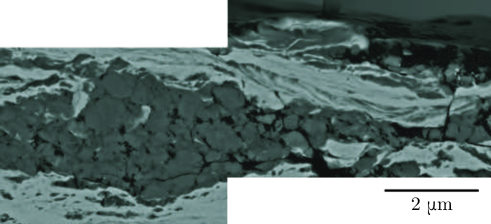
An in-situ lift-out was taken from an oxidised surface and shows that two oxide layers are formed on the surface of 316L after autoclaving in simulated PWR conditions for , Figure 2. The outer oxide layer can be seen to be made up of discrete crystallites, whilst the inner oxide was nanocrystalline and free of pores and voids at the metal-oxide interface.
Compositional information, found using STEM-EDX, showed that the outer oxide is Fe-rich and depleted of both Cr and Ni. In contrast, the inner oxide is Cr-rich as well as containing both Fe and Ni, Figure 2.
Structural information was found using XRD, showing that a single oxide structure was present, M3O4 (where M is a metal ion), often known as magnetite. The oxide peaks appeared as doublets, suggesting that both the inner and outer oxides have the same structure, but with differing lattice parameters, likely as a result of their different chemistries. The outer oxide was therefore found to be Fe-rich magnetite of composition Fe3O4, whilst the inner oxide is a Cr-rich magnetite of approximate composition Cr1.3Fe1.2Ni0.5O4, in agreement with Terachi et al. [27] and Kim [28].
3.2 Macroscopic Observations
| Sample | Galled Area / % | Sample Height / | ||
| Max | Min | Rt | ||
| (a) | 14 | 460 | -320 | 780 |
| (b) | 1 | 21 | -5 | 26 |
| (c) | 59 | 350 | -280 | 630 |
| (d) | 28 | 120 | -100 | 220 |
In the unoxidised condition, 316L stainless steel was seen to gall at the lowest applied stresses of . As a result, it was felt that the ASTM G98 standard concept of a threshold galling stress was not a suitable measure of galling, since it is a purely qualitative measure and would not differentiate between the extent of galling damage seen across different samples. As a result, quantitative measures developed by Ives et al. have been used in this work.
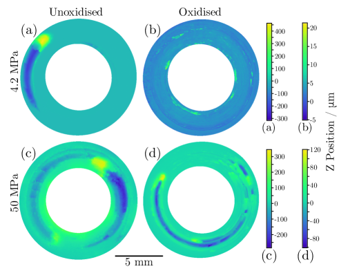
In the unoxidised condition at an applied normal stress of it was observed that 316L formed a single galling peak and trough with a sample Rt of and a galling area of , Figure 3. It was seen that when the applied normal stress was increased to the galled area was seen to increase, as expected, however, the sample Rt decreased to when compared with the sample tested at . Since two samples are required for the galling tests, by observing the damage on the other sample within the test pair, it was seen that the average Rt for the test pair galled at was in fact larger than that of the test pair galled at . There was, however, large variability in the Rt in unoxidised samples tested across the applied normal stress range making a conclusion regarding the effect of applied normal stress on Rt difficult.
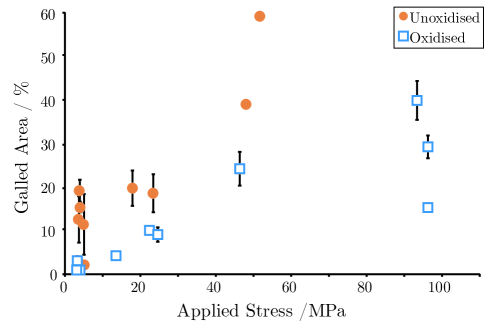
In contrast, the oxidised 316L stainless steel samples were seen to behave as expected, since both the Rt and galled area were seen to increase with increased applied normal stress across the full range of applied normal stresses, Figures 3 & 4.
For a given applied normal stress, the extent of galling seen by the unoxidised samples was considerably greater than that of the oxidised samples, Figure 3. For the samples tested at a low applied stress, the Rt was also on a different order of magnitude when comparing 316L in the unoxidised and oxidised conditions; vs. . Although a less pronounced difference was observed with regard to Rt, at high applied stresses, there was again a significant difference in the galled area, with the galled area being considerably larger when tested in the unoxidised condition; vs. , Figure 4. This is unsurprising, since it is well known that adsorbed oxygen in ambient conditions gives rise to adhesion resistance when compared with adhesion under vacuum, and an oxide layer is a surface film which is more wear resistant than adsorbed oxygen [29, 30].
The most crucial finding was that for one of the unoxidised tests at , seizure occurred before the end of the test, with the opposing surfaces needing to be pulled apart for observation.
It was also be noted that the number of galling prows on a surface appears to be larger on the oxidised samples than the unoxidised samples, where typically there are only one or two galling peaks, Figure 3. This suggests that either multiple galling instances take place simultaneously, or that prow growth is interrupted by oxide, and so abrasion recommences until metal-metal adhesion and subsequent galling can re-occur. The morphology of the galling scars was consistent throughout the tests, despite the change in damage magnitude. This behaviour suggests that the same mechanism was active for both the oxidised and unoxidised samples.
3.3 Galling Mechanisms
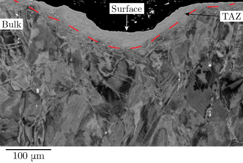
By sectioning galled samples radially, the subsurface deformation can be easily seen, Figure 5. The most apparent change in microstructure from the as-received material is the creation of a layer of material immediately beneath the gall scar. This layer is often referred to as the ‘white layer’, ‘tribologically transformed zone’ or ‘tribologically transformed structure’ [8]. Since a transformation in phase or atomic structure may not necessarily occur, in this paper, this region is termed the ‘tribologically affected zone’ (TAZ), analogous with the heat affected zone (HAZ) in welding, and will be discussed at length later in this paper. When viewed in a radial cross-section using an SEM, the structure of the TAZ is difficult to interpret from BSE images. The size of the trough depth and the TAZ depth beneath, can however be observed and noted as being and respectively, Figure 5, demonstrating that a significant damage layer is observed in galled samples.
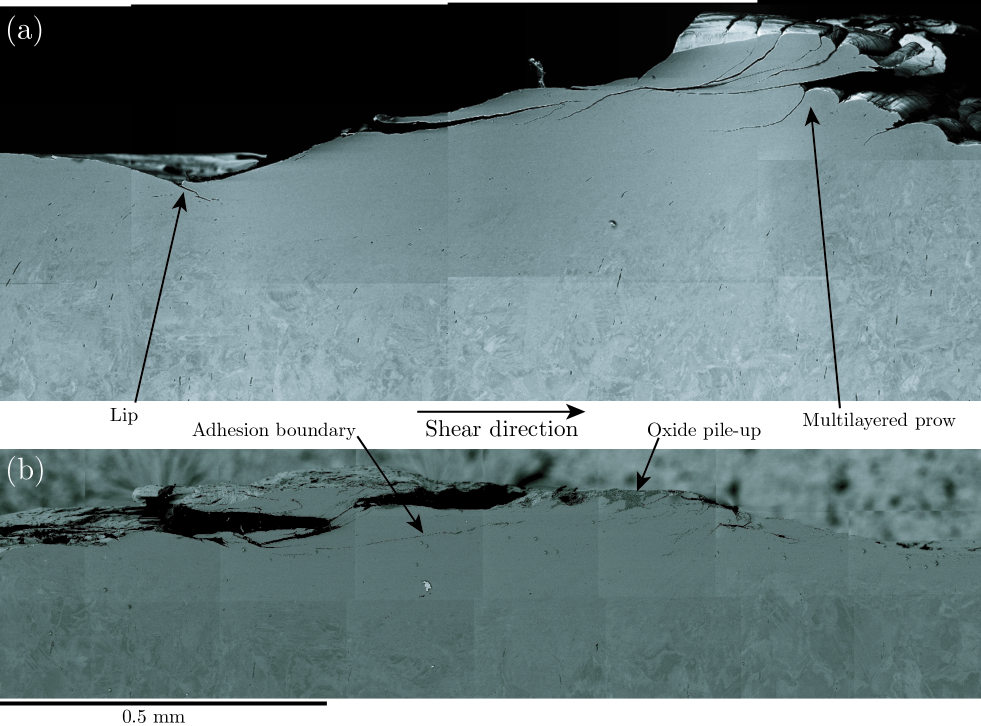
When viewed in the circumferential plane the mechanism is easier to rationalise, Figure 6. Although more obvious in the unoxidised sample, lips are seen to have formed within the galling trough, Figure 6. These lips are observed to be free of oxide. Similarly, in both the unoxidised and oxidised states a large multilayered prow is seen. In the oxidised state, these prows are not made of discrete layers, separated by a partially worn oxide surface, instead, having regions of mechanical mixing between the oxide layers and stainless steel substrate. This was particularly seen in radial cross-sections, where fine-scale mechanical mixing within peaks was observed, Figures 7 & 8. The prows are therefore unlikely to have formed through the accumulation of plucked material, instead, forming through shear. This is consistent with the formation of the lips, which are known to be formed through shear failure [31]. It is likely that as the prow grew it folded, and gave the appearance of a layered prow. This is particularly evident in the unoxidised sample at the front of the prow, where the surface is observed to have buckled, Figure 6(a). This can also be evidenced in the oxidised sample through the adhesion boundaries which are seen to contain a relatively large proportion of oxide, which appear not to be in intimate contact, Figure 6(b).
In order for the initial adhesion in the oxidised sample to take place, a metal-metal contact must first be achieved. This is due to oxide-oxide and oxide-metal adhesion bonds being very weak [32, 33]. This therefore means that abrasion and removal of the oxide layers on both mating surfaces must occur before adhesion and galling may take place. The removal of the oxide layers therefore occurs through abrasion, with the abraded oxide being deposited in valleys within the surface, or within sample folds, Figure 6(b).
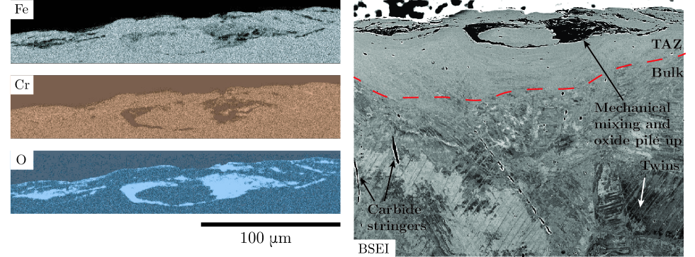
Figure 8 shows a radial cross-section of a galling peak on an oxidised sample. The BSE image shows that within the bulk material there is extensive twinning, however, these were present in the as-received material. Twins were identified and distinguished from deformation-induced -martensite by EBSD analysis. Immediately beneath the sample surface, oxide pile up as well as mechanical mixing of the surface, including oxides, can be seen, Figure 8. By performing EDX analysis it can be observed that both oxides have been both mechanically mixed and piled up, Figure 8. Between the region of mechanical mixing and the bulk, the TAZ is observed, however, it is difficult to interpret the microstructure of the TAZ using BSE in radial cross-sections. However, when observing the TAZ in a circumferential cross section, flow lines can be seen. In addition, although when viewed in radial cross-sections, carbide stringers appear unchanged from the as-received material, in circumferential cross-sections the carbide stringers are observed to follow flow lines, Figure 6(a). Since the carbide stringers are arranged perpendicular to the sample surface before-testing, by observing their post-test positions, it can be seen that extensive sub-surface shear has taken place, most notably by the shear lip, Figure 6(a).
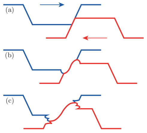
A number of galling mechanisms have been reported in the literature, however, only one of these was observed in the galling of 316L stainless steel; wedge formation and flow, Figure 9 [11, 14]. The wedge formation and flow mechanism is consistent with the observations of galled 316L stainless steel in the unoxidised condition by Peterson et al. [34].
Initially, adhesion of opposing surfaces takes place, either as two flat sections, in which case shear subsequently takes place to form a wedge [11, 14], or two asperities come into contact, essentially being pre-made wedges, Figure 9(a). Shear then continues to take place, causing material flow and wedge growth, Figure 9(b). As the prow continues to grow and is pushed from behind, the leading face of the prow will eventually fold over [35], causing an additional interface within the prow, which, due to the compressive stresses it is under, will likely form an adhesion junction. Simultaneously, the trailing face of the prow continues to move, shearing the sub-surface material, and resulting in the formation of ‘lips’ from shear failure, within the galling trough, 9(d) [31]. This then continues such that multiple folds are formed as the wedge grows, whilst additional ‘lips’ are seen, Figure 9.
3.4 Tribologically Affected Zone
Something which has been studied very little in the literature is the sub-surface structure which results from galling. It is known that immediately beneath the galling scar, the hardness of the material is increased [19], particularly in the tribologically affected zone (TAZ).
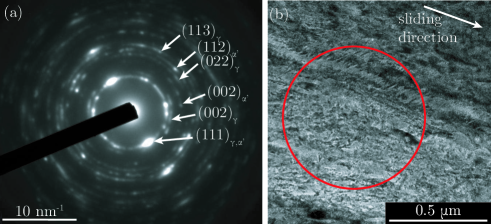
TEM imaging was used to discern the microstructure of the TAZ by removing a section of the TAZ from a radial cross-section with a FIB. The TAZ was observed to be a nanocrystalline region where grains are elongated in the shear direction, Figure 10. Since the sample was nanocrystalline, diffraction rings were formed, and the distance of these from the straight-through beam were measured and their crystal planes indexed. The indexing of these rings showed the presence of bcc-ferrite. This is surmised to be low-carbon (and hence low tetragonality) deformation-induced bct martensite formed without diffusion and compositional change. This conclusion was verified using X-ray diffraction (XRD) and STEM-EDX.
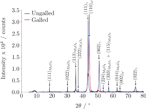
Figure 11 shows the XRD patterns obtained for oxidised 316L both pre- and post-galling and additional peaks are seen, which are in positions corresponding to a bcc-phase. STEM-EDX found that the concentration of Mn (an austenite stabiliser), was constant across the sample, verifying the fact that a low-tetragonality bct-martensite phase has formed as a result of the extensive shear experienced immediately below the galling surface.
4 Conclusion
In this work, 316L stainless steel was oxidised in simulated PWR conditions, forming a multilayer oxide. Both oxide layers were found, using XRD, to be magnetite, M3O4. Using STEM and STEM-EDX, the outer oxide was found to have a composition of Fe3O4, and was seen to have formed discrete single crystals across the sample surface. The inner oxide was found to be a continuous nanocrystalline layer which was Cr-rich, being of approximate composition Cr1.3Fe1.2Ni0.5O4.
When galled in both the unoxidised and oxidised. conditions, 316L stainless steel is seen to gall via the wedge formation & flow mechanism. In order for this mechanism to occur, however, sufficient oxide must be removed to enable an adhesion bond stronger than a cohesion bond local to the adhesion surface. This therefore means that abrasion or mechanical mixing must first occur before gall can take place when 316L is in the oxidised state, since oxide-oxide & metal-oxide adhesion bonds are significantly weaker than metal-metal adhesion bonds. For this reason, the galling performance of 316L stainless steel can be improved by around 30x ( vs. under a normal load of ) by forming an oxide scale.
A multilayered peak and a trough, with ‘lips’, indicative of shear fracture are formed during the galling and have been recorded as giving a sample Rt of up to . It has been observed that in both the oxidised and unoxidised states, an increase in normal load correspond to an increase in galling damage, as recorded using Rt and galling area.
Since shear failure occurs during the wedge formation & flow mechanism, it is unsurprising that immediately beneath the sample surface, a region of extensive shear is observed, named the tribologically affected zone, TAZ. The TAZ has been found to be nanocrystalline, being a mixture of parent austenite and martensite, formed during the shear deformation.
Acknowledgements
We gratefully acknowledge support from Rolls-Royce plc, from EPSRC (EP/N509486/1, EP/N025954/1 and EP/R000956/1) and from the Royal Society (D Dye Industry Fellowship).
References
References
- [1] M. Vannerem. Chemistry of operating civil nuclear reactors. ONR Guide NS-TAST-GD-088 Revision 2, Office for Nuclear Regulation, January 2019.
- [2] H. Ocken. The galling wear resistance of new iron-base hardfacing alloys: a comparison with established cobalt- and nickel-base alloys. Surface and Coatings Technology, 76-77:456–461, 1995.
- [3] D.H.E. Persson, S. Jacobson and S. Hogmark. Effect of temperature on friction and galling of laser processed norem 02 and stellite 21. Wear, 255(1):498–503, 2003.
- [4] D. Bowden. Assessment of cobalt-free hardfacing stainless steel alloys for nuclear applications. PhD thesis, University of Manchester, 2016.
- [5] J.H. Magee. Two galling resistant stainless steels used for bridge hinge pins. Technical report, Carpenter Technology Corporation, 2018.
- [6] Committee of Stainless Steel Producers. Review of the wear and galling characteristics of stainless steels. Handbook.
- [7] I. Inglis, E.V. Murphy and H. Ocken. Performance of wear-resistant iron base hardfacing alloys in valves operating under prototypical pressurized water reactor conditions. Surface and Coatings Technology, 53:101–106, 1992.
- [8] I. Hutchings and P. Shipway. Tribology: Friction and Wear of Engineering Materials. Butterworth-Heinemann, second edition edition, 2017.
- [9] M. Cocks. Wear debris in the contact between sliding metals. Journal of Applied Physics, 29:1609–1610, 1958.
- [10] M. Antler. Wear, friction, and electrical noise phenomena in sever sliding systems. ASLE Transactions, 5:297–307, 1962.
- [11] M. Antler. Processes of metal transfer and wear. Wear, 7(2):181–203, 1964.
- [12] T. Sasada and S. Norose. The formation and growth of wear particles through mutual material transfer. In Proceedings of the JSLE-ASLE International Lubrication Conference, p 82–91, 1976.
- [13] M. Cocks. Interaction of sliding metal surfaces. Journal of Applied Physics, 33(7):2152–2161, 1962.
- [14] M. Cocks. Role of displaced metal in the sliding of flat metal surfaces. Journal of Applied Physics, 35(6):1807–1814, June 1964.
- [15] W.A. Glaeser. Wear experiments in the scanning electron microscope. Wear, 73(2):371–386, 1981.
- [16] T. Kayaba, K. Kato and Y. Nagasawa. Abrasive wear in stick-slip motion. In Wear of Materials: International Conference on Wear of Materials, 1981, p 439–446, 1981.
- [17] T. Kayaba and K. Kato. The analysis of adhesive wear mechanism by successive observation of the wear process in sem. In Wear of Materials, p 45–56, April 1979.
- [18] R.T. Smith. Development of a Nitrogen-Modified Stainless-Steel Hardfacing Alloy. PhD thesis, The Ohio State University, 2015.
- [19] J.-K. Kim and S.-J. Kim. The temperature dependence of the wear resistance of iron-base NOREM 02 hardfacing alloy. Wear, 237(2):217–222, February 2000.
- [20] E. Sauger, L. Ponsonnet, J.M. Martin and L. Vincent. Study of the tribologically transformed structure created during fretting tests. Tribology International, 33(11):743–750, 2000.
- [21] V. Nurmi, J. Hintikka, J. Juoksukangas, M. Honkanen, M. Vippola, A. Lehtovaara, A. Mantyla, J. Vaara and T. Frondelius. The formation and characterization of fretting-induced degradation layers using quenched and tempered steel. Tribology International, 131:258–267, March 2019.
- [22] ASTM International. ASTM G98-17 standard test method for galling resistance of materials. Technical report, ASTM International, 2017.
- [23] ASTM International. ASTM G196-08(2016) standard test method for galling resistance of material couples. Technical report, ASTM International, 2016.
- [24] K.G. Budinski and S.T. Budinski. Interpretation of galling tests. Wear, 332(C):1185–1192, 2015.
- [25] L.K. Ives, M.B. Peterson and E.P. Whitenton. The mechanism, measurement, and influence of properties on the galling of metals. Technical Report NISTIR 89-4064, National Institute of Standards and Technology (NIST), December 1989.
- [26] H. Ocken. Reducing the cobalt inventory in light water reactors. Nuclear Technology, 68:18–28, January 1985.
- [27] T. Terachi, T. Yamada, T. Miyamoto, K. Arioka and K. Fukuya. Corrosion behavior of stainless steels in simulated pwr primary water—effect of chromium content in alloys and dissolved hydrogen. Journal of Nuclear Science and Technology, 45(10):975–984, 2008.
- [28] Y.-J. Kim. Characterization of the oxide film formed on type 316 stainless steel in 288C water in cyclic normal and hydrogen water chemistries. Corrosion, 51(11):849–860, 1995.
- [29] D.H. Buckley and R.L. Johnson. Friction and wear of hexagonal metals and alloys as related to crystal structure and lattice parameters in vacuum. ASLE Transactions, 9(2):121–135, 1966.
- [30] D.H. Buckley. Surface films and metallurgy related to lubrication and wear. Progress in Surface Science, 12(1):1–154, 1982.
- [31] O. Vingsbo. Wear and wear mechanisms. In Wear of Materials, p 620–635. ASME, 1979.
- [32] O.L. Anderson. Adhesion of solids: Principles and applications. Bell Laboratories Record, 35(11):441–445, 1957.
- [33] S.B. Ainbinder and A.S. Frančs. On the mechanism of the formation and destruction of adhesion junctions between bodies in frictional contact. Wear, 9(3):209–227, 1966.
- [34] M. Peterson, K.J. Bhansali, E.P. Whitenton and L.K. Ives. Galling wear of materials. In American Society of Mechanical Engineers Wear of Materials: International Conference: Papers, p 293–301, 1985.
- [35] H. Yeung, K. Viswanathan, A. Mahato and S. Chandrasekar. Surface phenomena revealed by in situ imaging: studies from adhesion, wear and cutting. Surface Topography: Metrology and Properties, 5(1):014002, 2017.