Nonreciprocal transport based on cavity Floquet modes in optomechanics
Abstract
Directional transport is obtained in various multimode systems by driving multiple, non-reciprocally-interfering interactions between individual bosonic modes. However, systems sustaining the required number of modes become physically complex. In our microwave-optomechanical experiment, we show how to configure nonreciprocal transport between frequency components of a single superconducting cavity coupled to two drumhead oscillators. The frequency components are promoted to Floquet modes and generate the missing dimension to realize an isolator and a directional amplifier. A second cavity left free by this arrangement is used to cool the mechanical oscillators and bring the transduction noise close to the quantum limit. We furthermore uncover a new type of instability specific to nonreciprocal coupling. Our approach is generic and can greatly simplify quantum signal processing and the design of topological lattices from low-dimensional systems.
Introduction.– While lattices with a high level of complexity exist in nature, building these in a bottom-up fashion while aiming on specific functionalities remains challenging. Doing so, however, would be highly desirable in order to utilize topological phenomena in applications. The construction of artificial lattices has therefore been investigated in cold atoms Goldman et al. (2016), photonics Lu et al. (2014), superconducting circuits Koch et al. (2010); Tsomokos et al. (2010); Kollár et al. (2019), and cavity optomechanics Peano et al. (2015); Schmidt et al. (2015). An intriguing possibility that has received attention recently to demonstrate complex functionalities in a physically low-dimensional system is to complement it with synthetic dimensions Ozawa and Price (2019). Initially, atoms’ internal degrees of freedom were identified as lattice sites Celi et al. (2014) aligned along a non-spatial, synthetic dimension supplementing existing spatial dimensions. Floquet quasienergy levels that emerge in a periodically driven nonlinear system Rechtsman et al. (2013); Martin et al. (2017); Lin et al. (2018); Baum and Refael (2018); Crowley et al. (2019); Peterson et al. (2019); Dutt et al. (2019), as well as multiple or degenerate resonant modes Andrijauskas et al. (2018); Lin et al. (2018); Chen et al. (2019) have also been considered as lattice sites in additional dimensions. Interestingly, nontrivial topology can be designed in these synthetic dimensions just as in spatial dimensions, which, among many other phenomena, can lead to nonreciprocal transport Wanjura et al. (2019).
We focus on microwave cavity optomechanics Regal et al. (2008); Teufel et al. (2011) where microwave resonators interact with mechanical vibrations. Microwave-optomechanical signal processing either reciprocal Massel et al. (2011); Ockeloen-Korppi et al. (2016, 2017); Tóth et al. (2017) or nonreciprocal Malz et al. (2018); Peterson et al. (2017); Bernier et al. (2017); Barzanjeh et al. (2017); Mercier de Lépinay et al. (2019) shows some advantages over Josephson-junctions-based processing Movshovich et al. (1990); Castellanos-Beltran et al. (2008); Abdo et al. (2013); Zhong et al. (2013); Abdo et al. (2014); Eichler et al. (2014); Sliwa et al. (2015); Lecocq et al. (2017); Westig and Klapwijk (2018): saturation powers are orders of magnitude higher and superconductivity is not fundamentally necessary. Multimode optomechanical nonreciprocal devices have recently been suggested Hafezi and Rabl (2012); Metelmann and Clerk (2015); Xu and Li (2015); Xu et al. (2016); Li et al. (2017); Jiang et al. (2018a); Malz et al. (2018); Jiang et al. (2018b) and demonstrated Hua et al. (2016); Shen et al. (2016); Ruesink et al. (2016); Fang et al. (2017); Shen et al. (2018); Ruesink et al. (2018). Progress in this direction has nonetheless been hindered by the difficulty of fabricating devices with multiple mechanical modes coupled equivalently and strongly enough to multiple electromagnetic modes. The use of a single cavity mode for several simultaneous operations has been considered for passive detection of stronger processes Lecocq et al. (2015); Wollman et al. (2015); Ockeloen-Korppi et al. (2018). Kerr-type nonlinearities have also been shown to promote coupling between Floquet modes Qiu et al. (2019). However, exciting a single cavity mode so that driven Floquet components actively participate in the dynamics has received little attention, with the notable exception of Ref. Xu et al. (2019) where the phase difference of two components of a single cavity field is used to realize nonreciprocal mechanical noise transport.
In this work, we show that configurable and directional electromagnetic-signal transmission can be obtained in an optomechanical system by designing a loop of interactions in the synthetic plane generated by driven Floquet modes on one hand and multiple mechanical modes on the other hand to realize a microwave isolator and a directional amplifier. The use of Floquet modes thus demonstrated provides a way to simplify these nonreciprocal devices and alleviate practical requirements.

Principle.– Let us first consider a multimode cavity optomechanical system as shown on Fig. 1(a) similar to the ones used in a number of directional transduction demonstrations Bernier et al. (2017); Barzanjeh et al. (2017); Peterson et al. (2017); Mercier de Lépinay et al. (2019). It has two mechanical oscillators that are both coupled to two cavity modes. Both cavities are excited with several coherent pumping tones. Each set of tones enhances one mechanically-mediated coupling mechanism between the cavities, and the relative phase of pump tones controls the interference between these two coupling processes.
We demonstrate that this physical system can be recast into the one on Fig. 1(b) where different frequency components of one of the cavity fields belonging to a driven Floquet system play the role of the two cavity modes. The second cavity is left available for auxiliary optomechanical manipulations. The mediating mechanical modes still participate at their respective resonance frequencies [see Fig. 1(c)] and their narrow bandwidths play an essential role by restricting the number of Floquet manifolds coupled together.
Let us first consider the configuration of the Floquet directional amplifier. The pertaining pump angular frequencies are as schematized in Fig. 1(d): . We define the frequency of the cavity, of the mechanical oscillator , the linewidths of the oscillators and the detuning of the pumps much larger than the mechanical linewidth but smaller than the cavity linewidth . The mechanical damping rates are here assumed to already include auxiliary optical damping. The detunings are comparable to and allow to drive mechanical susceptibilities out of resonance.
To realize instead a Floquet-mode isolator, all four pump tones are placed close to the red sidebands and the pumps angular frequencies become [see Fig. 1(e)] . In both devices, the pumps drive components of the cavity field away from resonance. The frequency ranges around these detunings play the roles of the two ports of either device instead of cavity modes [see Fig. 1(d)]. The equations of evolution for electromagnetic and mechanical operators, linearized and with fast rotating terms ignored, display time-dependencies that cannot be eliminated by moving to a rotating frame. For example, for the isolator in the frame rotating with where are photonic creation and annihilation operators, and analogous phononic operators for oscillator , the Langevin equation read:
| (1) |
is the enhanced optomechanical coupling for the pump detuned by associated to mechanical mode , where is the single-photon optomechanical coupling of mode to the cavity and the cavity field amplitude at the frequency of the corresponding pump. The terms and model respectively the fluctuating and coherent probe drives of the cavity and the fluctuating drive of mechanical oscillator . The total cavity linewidth is the sum of the external and internal loss rates . We introduce cooperativities for each pump and the only relevant phase degree of freedom Malz et al. (2018) between pumps, such that , and for . The phase is a crucial parameter as it determines the nonreciprocal nature of the coupling and therefore the directionality of the transduction. Since is by far the smallest frequency scale of the system, narrow mechanical susceptibilities restrict the number of relevant harmonics to two only at detunings and from the cavity resonance frequency sup . These Floquet components define the two ports of the device, thereafter named respectively port 1 and 2.
Eliminating phononic operators from Fourier transformed Eqs. (1), it follows that a 2-vector of cavity operators is invariant under the evolution equations: in the case of the isolator and in the case of the amplifier. Defining a global cavity susceptibility matrix sup , the vector is related to similarly-defined drive vectors and by: . Using an analogous definition for the cavity output rate , the input-output relation reads . Therefore, the scattering matrix defined by (temporarily omitting noise terms) is . The elements of this matrix define the scattering parameters between ports and .
Experiment.– An on-chip microwave circuit lithographied in aluminum sustains two electromagnetic cavity modes. We coin these “primary” and “auxiliary” modes. The former is used to establish nonreciprocal transfer and the latter to sideband-cool the mechanical modes Schliesser et al. (2008) in order to reduce noise and broaden the bandwidth. The cavity modes have respective frequencies and , and internal and external decay rates , and , . The circuit includes two vacuum-gap capacitors [see Fig. 1(f)] whose top plate is allowed to move freely, materializing two mechanical oscillators of frequencies and and intrinsic decay rates and . The chip is mounted in a dilution cryostat to be operated at a temperature of .
Isolator.– We now discuss the configuration shown in Fig. 1(e) that employs only red-sideband tones. The global susceptibility matrix in the basis defined by is modified by a coupling matrix :
| (2) |
Diagonal coupling terms () account for standard backaction of mechanical modes on Floquet cavity modes from the two pumps detuned by (. Off-diagonal terms () also involve one contribution from each mechanically-mediated coupling path between Floquet cavity modes:
| (3) |
where is the susceptibility of mechanical mode , centered on : . Off-diagonal elements of the scattering matrix and are proportional to and respectively sup . Therefore, to obtain e.g. isolation of port 1 (), it suffices to cancel out . In order to maintain simultaneous transfer in the other direction, one must ensure that , and therefore , is concurrently as high as possible. This asymmetry is made possible thanks to the phase-shift of each coupling path provided by the off-resonance participation of either mechanical oscillator sup .
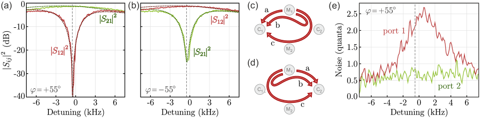
The experiment is prepared by sideband-cooling mechanical oscillators through the auxiliary cavity down to and quanta. Corresponding effective mechanical linewidths are and . The primary cavity is pumped with detuning , much larger than the effective mechanical damping rates. With cooperativities and additional detunings , we show on Fig. 2(a) an optimal isolation for of with insertion loss. We also demonstrate for the opposite phase a device working in the reversed direction on Fig. 2(b) with isolation and insertion loss. The bandwidth around is comparable to the effective mechanical linewidths. Due to relatively small mechanical frequency separation, pumps also excite the mechanical mode they are not intended to drive, leading to dynamical backaction taken into account in the theoretical fits presented throughout the paper.
The noise in the device arises mainly from mechanical thermal noise Malz et al. (2018) which propagates through 3 paths as indicated on Fig. 2(c): path “a” is the direct conversion of phonons into the same amount of cavity photons. The two others (“b” and “c”) follow the same route as signals across the device and interfere destructively at the isolated port. Therefore, only path “a” contributes to the backward-propagating noise which is thus simply half of the mechanical oscillators’ total occupation: in the limit of high cooperativities and ideal cavity. Here we maintain this noise around quanta [see Fig. 2(e)]. By comparison, without sideband-cooling, the expected input-port noise is photons in the ideal case. At the other port [see Fig. 2(d)], direct path “a” interferes somewhat destructively with the sum of the indirect paths “b” and “c” and mitigates total fluctuations, which results in very small output noise of thermal origin, and thus quanta [see Fig. 2(e)].
Directional amplifier.– Owing to blue-sideband driving, the S-parameters of the amplifier relate to : they exchange quadratures between input and output ports. This translates the phase-preserving but phase-conjugating nature of the device Caves (1982) and entails that signals sent at a frequency are converted at Mercier de Lépinay et al. (2019), that is, the output frequency is mirrored around the port’s central frequency. As long as the detunings are small compared to , the gain in the limit of ideal cavities and large cooperativities remains the same as for separate-cavity amplifiers Malz et al. (2018); Mercier de Lépinay et al. (2019); sup :
| (4) |
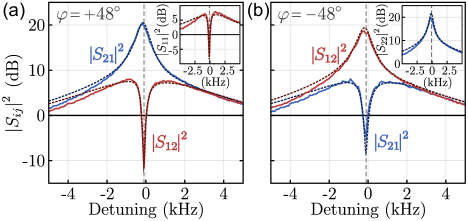
With similar pre-cooling of mechanical modes () and same detuning as for the isolator, we use cooperativities to demonstrate in Fig. 3(a) for a maximum amplification gain of and a simultaneous isolation of . The amplification and the isolation bandwidths and respectively are again comparable to the mechanical linewidths, but lower than those of the isolator since they are not enhanced by parasitic coupling sup . Fig. 3(b) also shows a gain of and a simultaneous isolation of with the opposite phase . However, contrary to the case of the isolator, only one port can be impedance-matched to the transmission line due to the asymmetric pumping of red sidebands of one Floquet mode and blue sidebands of the other sup . As a result of this asymmetry, regardless of the phase, port 1 displays low reflectivity and port 2 a large one [see insets to Fig. 3(a) and (b)]. The optimal configuration is therefore which suppresses power reflected on the input port by .
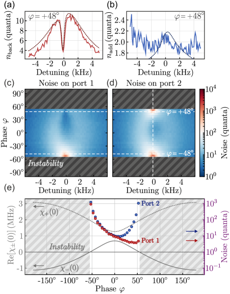
In contrast to the isolator, fluctuations propagating across the amplifier are amplified, which results in a generally high noise. However, we measure in this configuration only quanta at port 1 when it is isolated at [see Fig. 4(c)]. Indeed, amplified paths “b” and “c” again interfere destructively and only the non-amplified noise from direct path “a” contributes to the backwards noise which is again, in the high cooperativities limit, half of the total mechanical occupancy and is reduced thanks to active cooling. Output noise results from the same three-path interference as in the isolator and at phase the added noise is photons [see Fig. 4(b)], close to the quantum limit of 0.5 photons. On the other hand, for , port 2 which displays high reflective gain outputs a backward-propagating noise reaching quanta even with aggressive auxiliary cooling. This asymmetry between noise at phases is visible on Fig. 4(c) and (d). This represents a second reason, together with asymmetric impedance-matching, for which the behavior of the device is not inverted by simply changing the sign of the phase.
Phase-dependent instability.– Nonreciprocal amplification furthermore reveals a type of instability for a range of phases. Contrary to optomechanical instability, it does not arise directly from a strong blue-sideband driving but is related to the emergence of an unstable eigenmode of the coupling matrix . Figures 4(c) and (d) show the amplifier noise for a limited range of phase parameters because the device is unstable for the rest of the range. As shown in Fig. 4(e), the onset of the instability coincides with the phase at which one of the eigenvalues of the electromagnetic susceptibility matrix acquires a negative real-part, which is tantamount to a negative damping rate. Figure 4(e) furthermore shows that the noise diverges at these phases. In the isolator case, on the other hand, the eigenvalue with lower real-part is stabilized by dynamical backaction and never crosses zero. The observed instability is therefore specific to nonreciprocally coupled, non-stabilized multimode devices. As such, it relates to the instability observed in other phase-preserving nonreciprocal coupling cases Gloppe et al. (2014).
Conclusion.– We have theoretically and experimentally demonstrated a new archetype of nonreciprocal optomechanical devices based on the interference of Floquet modes in a single cavity. This physical simplification allows to accommodate auxiliary optomechanical manipulations of mechanical oscillators to closely approach the quantum limit of the transduction. We foresee that this approach can greatly simplify signal processing in other physical platforms involving resonators. Finally, we uncovered a class of instability arising in nonreciprocally-coupled systems provided they are not stabilized by dynamical backaction.
Acknowledgements.
We thank Andreas Nunnenkamp, Clara Wanjura and Matteo Brunelli for useful discussions. This work was supported by the Academy of Finland (contracts 308290, 307757), by the European Research Council (615755-CAVITYQPD), and by the Aalto Centre for Quantum Engineering. The work was performed as part of the Academy of Finland Centre of Excellence program (project 312057). We acknowledge funding from the European Union’s Horizon 2020 research and innovation program under grant agreement No. 732894 (FETPRO HOT). D.M. acknowledges funding from ERC Advanced Grant QENOCOBA under the EU Horizon 2020 program (Grant Agreement No. 742102). We acknowledge the facilities and technical support of Otaniemi research infrastructure for Micro and Nanotechnologies (OtaNano) that is part of the European Microkelvin Platform.References
- Goldman et al. (2016) N. Goldman, J. C. Budich, and P. Zoller, “Topological quantum matter with ultracold gases in optical lattices,” Nat. Phys. 12, 639 (2016).
- Lu et al. (2014) L. Lu, J. D. Joannopoulos, and M. Soljačić, “Topological photonics,” Nat. Photonics 8, 821 (2014).
- Koch et al. (2010) J. Koch, A. A. Houck, K. Le Hur, and S. M. Girvin, “Time-reversal-symmetry breaking in circuit-QED-based photon lattices,” Phys. Rev. A 82, 043811 (2010).
- Tsomokos et al. (2010) D. I. Tsomokos, S. Ashhab, and F. Nori, “Using superconducting qubit circuits to engineer exotic lattice systems,” Phys. Rev. A 82, 052311 (2010).
- Kollár et al. (2019) A. J. Kollár, M. Fitzpatrick, and A. A. Houck, “Hyperbolic lattices in circuit quantum electrodynamics,” Nature 571, 45 (2019).
- Peano et al. (2015) V. Peano, C. Brendel, M. Schmidt, and F. Marquardt, “Topological phases of sound and light,” Phys. Rev. X 5, 031011 (2015).
- Schmidt et al. (2015) M. Schmidt, S. Kessler, V. Peano, O. Painter, and F. Marquardt, “Optomechanical creation of magnetic fields for photons on a lattice,” Optica 2, 635 (2015).
- Ozawa and Price (2019) T. Ozawa and H. M. Price, “Topological quantum matter in synthetic dimensions,” Nat. Rev. Phys. 1, 349 (2019).
- Celi et al. (2014) A. Celi, P. Massignan, J. Ruseckas, N. Goldman, I. B. Spielman, G. Juzeliūnas, and M. Lewenstein, “Synthetic gauge fields in synthetic dimensions,” Phys. Rev. Lett. 112, 043001 (2014).
- Rechtsman et al. (2013) M. C. Rechtsman, J. M. Zeuner, Y. Plotnik, Y. Lumer, D. Podolsky, F. Dreisow, S. Nolte, M. Segev, and A. Szameit, “Photonic Floquet topological insulators,” Nature 496, 196 (2013).
- Martin et al. (2017) I. Martin, G. Refael, and B. Halperin, “Topological frequency conversion in strongly driven quantum systems,” Phys. Rev. X 7, 041008 (2017).
- Lin et al. (2018) Q. Lin, X.-Q. Sun, M. Xiao, Sh.-Ch. Zhang, and Sh. Fan, “A three-dimensional photonic topological insulator using a two-dimensional ring resonator lattice with a synthetic frequency dimension,” Sci. Adv. 4 (2018).
- Baum and Refael (2018) Y. Baum and G. Refael, “Setting Boundaries with Memory: Generation of Topological Boundary States in Floquet-Induced Synthetic Crystals,” Phys. Rev. Lett. 120, 106402 (2018).
- Crowley et al. (2019) P. J. D. Crowley, I. Martin, and A. Chandran, “Topological classification of quasiperiodically driven quantum systems,” Phys. Rev. B 99, 064306 (2019).
- Peterson et al. (2019) C. W. Peterson, W. A. Benalcazar, M. Lin, T. L. Hughes, and G. Bahl, “Strong Nonreciprocity in Modulated Resonator Chains through Synthetic Electric and Magnetic Fields,” Phys. Rev. Lett. 123, 063901 (2019).
- Dutt et al. (2019) A. Dutt, M. Minkov, Q. Lin, L. Yuan, D. A. B. Miller, and S. Fan, “Experimental band structure spectroscopy along a synthetic dimension,” Nat. Commun. 10, 3122 (2019).
- Andrijauskas et al. (2018) T. Andrijauskas, I. B. Spielman, and G. Juzeliūnas, “Topological lattice using multi-frequency radiation,” New J. Phys. 20, 055001 (2018).
- Chen et al. (2019) Y. Chen, Y.-L. Zhang, Zh. Shen, Zou Ch.-L., G.-C. Guo, and Ch.-H. Dong, “Synthetic gauge field in a single optomechanical resonator,” arXiv:1908.04456 (2019).
- Wanjura et al. (2019) C. C. Wanjura, M. Brunelli, and A. Nunnenkamp, “Topological framework for directional amplification in driven-dissipative cavity arrays,” arXiv:1909.11647 (2019).
- Regal et al. (2008) C. A. Regal, J. D. Teufel, and K. W. Lehnert, “Measuring nanomechanical motion with a microwave cavity interferometer,” Nat. Phys. 4, 555 (2008).
- Teufel et al. (2011) J. D. Teufel, T. Donner, D. Li, J. W. Harlow, M. S. Allman, K. Cicak, A. J. Sirois, J. D. Whittaker, K. W. Lehnert, and R. W. Simmonds, “Sideband cooling of micromechanical motion to the quantum ground state,” Nature 475, 359 (2011).
- Massel et al. (2011) F. Massel, T. T. Heikkilä, J.-M. Pirkkalainen, S. U. Cho, H. Saloniemi, P. J. Hakonen, and M. A. Sillanpää, “Microwave amplification with nanomechanical resonators,” Nature 480, 351 (2011).
- Ockeloen-Korppi et al. (2016) C. F. Ockeloen-Korppi, E. Damskägg, J.-M. Pirkkalainen, T. T. Heikkilä, F. Massel, and M. A. Sillanpää, “Low-noise amplification and frequency conversion with a multiport microwave optomechanical device,” Phys. Rev. X 6, 041024 (2016).
- Ockeloen-Korppi et al. (2017) C. F. Ockeloen-Korppi, E. Damskägg, J.-M. Pirkkalainen, T. T. Heikkilä, F. Massel, and M. A. Sillanpää, “Noiseless quantum measurement and squeezing of microwave fields utilizing mechanical vibrations,” Phys. Rev. Lett. 118, 103601 (2017).
- Tóth et al. (2017) L. D. Tóth, N. R. Bernier, A. Nunnenkamp, A. K. Feofanov, and T. J. Kippenberg, “A dissipative quantum reservoir for microwave light using a mechanical oscillator,” Nat. Phys. 13, 787 (2017).
- Malz et al. (2018) D. Malz, L. D. Tóth, N. R. Bernier, A. K. Feofanov, T. J. Kippenberg, and A. Nunnenkamp, “Quantum-Limited Directional Amplifiers with Optomechanics,” Phys. Rev. Lett. 120, 023601 (2018).
- Peterson et al. (2017) G. A. Peterson, F. Lecocq, K. Cicak, R. W. Simmonds, J. Aumentado, and J. D. Teufel, “Demonstration of efficient nonreciprocity in a microwave optomechanical circuit,” Phys. Rev. X 7, 031001 (2017).
- Bernier et al. (2017) N. R. Bernier, L. D. Tóth, A. Koottandavida, M. A. Ioannou, D. Malz, A. Nunnenkamp, A. K. Feofanov, and T. J. Kippenberg, “Nonreciprocal reconfigurable microwave optomechanical circuit,” Nat. Commun. 8, 604 (2017).
- Barzanjeh et al. (2017) S. Barzanjeh, M. Wulf, M. Peruzzo, M. Kalaee, P. B. Dieterle, O. Painter, and J. M. Fink, “Mechanical on-chip microwave circulator,” Nat. Commun. 8, 953 (2017).
- Mercier de Lépinay et al. (2019) L. Mercier de Lépinay, E. Damskägg, C. F. Ockeloen-Korppi, and M. A. Sillanpää, “Realization of Directional Amplification in a Microwave Optomechanical Device,” Phys. Rev. Applied 11, 034027 (2019).
- Movshovich et al. (1990) R. Movshovich, B. Yurke, P. G. Kaminsky, A. D. Smith, A. H. Silver, R. W. Simon, and M. V. Schneider, “Observation of zero-point noise squeezing via a Josephson-parametric amplifier,” Phys. Rev. Lett. 65, 1419 (1990).
- Castellanos-Beltran et al. (2008) M. A. Castellanos-Beltran, K. D. Irwin, G. C. Hilton, L. R. Vale, and K. W. Lehnert, “Amplification and squeezing of quantum noise with a tunable Josephson metamaterial,” Nat. Phys. 4, 929 (2008).
- Abdo et al. (2013) B. Abdo, K. Sliwa, L. Frunzio, and M. Devoret, “Directional Amplification with a Josephson Circuit,” Phys. Rev. X 3, 031001 (2013).
- Zhong et al. (2013) L. Zhong, E. P. Menzel, R. Di Candia, P. Eder, M. Ihmig, A. Baust, M. Haeberlein, E. Hoffmann, K. Inomata, T. Yamamoto, Y. Nakamura, E. Solano, F. Deppe, A. Marx, and R. Gross, “Squeezing with a flux-driven Josephson parametric amplifier,” New J. Phys. 15, 125013 (2013).
- Abdo et al. (2014) B. Abdo, K. Sliwa, S. Shankar, M. Hatridge, L. Frunzio, R. Schoelkopf, and M. Devoret, “Josephson Directional Amplifier for Quantum Measurement of Superconducting Circuits,” Phys. Rev. Lett. 112, 167701 (2014).
- Eichler et al. (2014) C. Eichler, Y. Salathe, J. Mlynek, S. Schmidt, and A. Wallraff, “Quantum-limited amplification and entanglement in coupled nonlinear resonators,” Phys. Rev. Lett. 113, 110502 (2014).
- Sliwa et al. (2015) K. M. Sliwa, M. Hatridge, A. Narla, S. Shankar, L. Frunzio, R. J. Schoelkopf, and M. H. Devoret, “Reconfigurable Josephson Circulator/Directional Amplifier,” Phys. Rev. X 5, 041020 (2015).
- Lecocq et al. (2017) F. Lecocq, L. Ranzani, G. A. Peterson, K. Cicak, R. W. Simmonds, J. D. Teufel, and J. Aumentado, “Nonreciprocal Microwave Signal Processing with a Field-Programmable Josephson Amplifier,” Phys. Rev. Applied 7, 024028 (2017).
- Westig and Klapwijk (2018) M. P. Westig and T. M. Klapwijk, “Josephson Parametric Reflection Amplifier with Integrated Directionality,” Phys. Rev. Applied 9, 064010 (2018).
- Hafezi and Rabl (2012) M. Hafezi and P. Rabl, “Optomechanically induced non-reciprocity in microring resonators,” Opt. Express 20, 7672 (2012).
- Metelmann and Clerk (2015) A. Metelmann and A. A. Clerk, “Nonreciprocal Photon Transmission and Amplification via Reservoir Engineering,” Phys. Rev. X 5, 021025 (2015).
- Xu and Li (2015) X.-W. Xu and Y. Li, “Optical nonreciprocity and optomechanical circulator in three-mode optomechanical systems,” Phys. Rev. A 91, 053854 (2015).
- Xu et al. (2016) X.-W. Xu, Y. Li, A.-X. Chen, and Y.-X. Liu, “Nonreciprocal conversion between microwave and optical photons in electro-optomechanical systems,” Phys. Rev. A 93, 023827 (2016).
- Li et al. (2017) Y. Li, Y. Y. Huang, X. Z. Zhang, and L. Tian, “Optical directional amplification in a three-mode optomechanical system,” Opt. Express 25, 18907 (2017).
- Jiang et al. (2018a) C. Jiang, L. N. Song, and Y. Li, “Directional amplifier in an optomechanical system with optical gain,” Phys. Rev. A 97, 053812 (2018a).
- Jiang et al. (2018b) Y. Jiang, S. Maayani, T. Carmon, F. Nori, and H. Jing, “Nonreciprocal phonon laser,” Phys. Rev. Applied 10, 064037 (2018b).
- Hua et al. (2016) S. Hua, J. Wen, X. Jiang, Q. Hua, L. Jiang, and M. Xiao, “Demonstration of a chip-based optical isolator with parametric amplification,” Nat. Commun. 7, 13657 (2016).
- Shen et al. (2016) Z. Shen, Y.-L. Zhang, Y. Chen, C.-L. Zou, Y.-F. Xiao, X.-B. Zou, F.-W. Sun, G.-C. Guo, and C.-H. Dong, “Experimental realization of optomechanically induced non-reciprocity,” Nat. Photonics 10, 657 (2016).
- Ruesink et al. (2016) F. Ruesink, M.-A. Miri, A. Alù, and E. Verhagen, “Nonreciprocity and magnetic-free isolation based on optomechanical interactions,” Nat. Commun. 7, 13662 (2016).
- Fang et al. (2017) K. Fang, J. Luo, A. Metelmann, M. H. Matheny, F. Marquardt, A. A. Clerk, and O. Painter, “Generalized non-reciprocity in an optomechanical circuit via synthetic magnetism and reservoir engineering,” Nat. Phys. 13, 465 (2017).
- Shen et al. (2018) Z. Shen, Y.-L. Zhang, Y. Chen, F.-W. Sun, X.-B. Zou, G.-C. Guo, C.-L. Zou, and C.-H. Dong, “Reconfigurable optomechanical circulator and directional amplifier,” Nat. Commun. 9, 1797 (2018).
- Ruesink et al. (2018) F. Ruesink, J. P. Mathew, M.-A. Miri, A. Alù, and E. Verhagen, “Optical circulation in a multimode optomechanical resonator,” Nat. Commun. 9, 1798 (2018).
- Lecocq et al. (2015) F. Lecocq, J. B. Clark, R. W. Simmonds, J. Aumentado, and J. D. Teufel, “Quantum Nondemolition Measurement of a Nonclassical State of a Massive Object,” Phys. Rev. X 5, 041037 (2015).
- Wollman et al. (2015) E. E. Wollman, C. U. Lei, A. J. Weinstein, J. Suh, A. Kronwald, F. Marquardt, A. A. Clerk, and K. C. Schwab, “Quantum squeezing of motion in a mechanical resonator,” Science 349, 952 (2015).
- Ockeloen-Korppi et al. (2018) C. F. Ockeloen-Korppi, E. Damskägg, J. M. Pirkkalainen, M. Asjad, A. A. Clerk, F. Massel, M. J. Woolley, and M. A. Sillanpää, “Stabilized entanglement of massive mechanical oscillators,” Nature 556, 478 (2018).
- Qiu et al. (2019) L. Qiu, I. Shomroni, M. A. Ioannou, N. Piro, D. Malz, A. Nunnenkamp, and T. J. Kippenberg, “Floquet dynamics in the quantum measurement of mechanical motion,” Phys. Rev. A 100, 053852 (2019).
- Xu et al. (2019) H. Xu, L. Jiang, A. A. Clerk, and J. G. E. Harris, “Nonreciprocal control and cooling of phonon modes in an optomechanical system,” Nature 568, 65 (2019).
- (58) See Supplemental Material for experimental and theoretical details.
- Schliesser et al. (2008) A. Schliesser, R. Rivière, G. Anetsberger, O. Arcizet, and T. J. Kippenberg, “Resolved-sideband cooling of a micromechanical oscillator,” Nature Physics 4, 415 (2008).
- Caves (1982) C. M. Caves, “Quantum limits on noise in linear amplifiers,” Phys. Rev. D 26, 1817 (1982).
- Gloppe et al. (2014) A. Gloppe, P. Verlot, E. Dupont-Ferrier, A. G. Kuhn, A. Siria, P. Poncharal, G. Bachelier, P. Vincent, and O. Arcizet, “Bidimensional nano-optomechanics and topological backaction in a non-conservative radiation force field,” Nature Nanotechnol. 9, 920 (2014).