Cryogenic platform for coupling color centers in diamond
membranes to a fiberbased microcavity
Abstract
We operate a fiberbased cavity with an inserted diamond membrane containing ensembles of silicon vacancy centers (SiV-) at cryogenic temperatures K. The setup, sample fabrication and spectroscopic characterization is described, together with a demonstration of the cavity influence by the Purcell effect. This paves the way towards solid state qubits coupled to optical interfaces as long-lived quantum memories.
I Introduction
Color centers in diamond emerged as promising candidates for a broad field of applications, including quantum sensing Fuchs et al. (2018), quantum communication Leifgen et al. (2014); Humphreys et al. (2018); Nguyen et al. (2019a); Bradley et al. (2019) and quantum memories Maurer et al. (2012); Bar-Gill et al. (2013). Such applications require stable solid state emitters with lifetime-limited emission lines, which for several color center species, can be achieved using a high-quality, low strain crystal host at cryogenic temperatures Sukachev et al. (2017); Iwasaki et al. (2015); Trusheim et al. (2020).
Various approaches aim to improve the photon collection from solid state emitters, employing solid immersion lenses Robledo et al. (2011); Hadden et al. (2010), nanopillars Maletinsky et al. (2012) or waveguides Mouradian et al. (2015). Coupling the emitter to a nanophotonic Zhang et al. (2018); Nguyen et al. (2019a); Riedrich-Möller
et al. (2014), nano-fiberbased Romagnoli et al. (2020) or open Albrecht et al. (2013); Riedel et al. (2017); Kaupp et al. (2016); Häußler et al. (2019); Nair et al. (2019) optical cavity can be used to both enhance the emission into the zero-phonon line (ZPL) for emitter species with small Debye-Waller factors, like the NV- center, as well as to funnel the emission into a well-collectable optical mode via the Purcell effect. While photonic crystal cavities are attractive due to strong mode confinement Zhang et al. (2018) and their intrinsic robustness, processing the crystal environment can lead to spectral diffusion and the optical outcoupling of the signal is challenging Nguyen et al. (2019b). Open, fiberbased Fabry-Pérot microcavities have been successfully utilized for various physical systems, like neutral atoms Colombe et al. (2007); Gallego et al. (2018), ions Brandstätter
et al. (2013); Meyer et al. (2015); Pfister et al. (2016) or quantum dots Muller et al. (2009), as they allow for direct coupling between the fiber and the cavity mode, small mode volumes as well as full spectral and spatial tunability. In recent experiments, color centers incorporated in nanodiamonds were coupled to fiberbased microcavities Albrecht et al. (2013); Kaupp et al. (2016); Benedikter et al. (2017). However, the embedded emitters often suffer from spectral diffusion Lindner et al. (2018) and insufficient photostability Benedikter et al. (2017). Recently, micrometer thin diamond membranes Ruf et al. (2019) have shown to be promising hosts for color centers used in microcavity experiments Riedel et al. (2017); Häußler et al. (2019); Nair et al. (2019).
Here, we present an experimental platform to couple color centers incorporated in single crystal diamond (SCD) membranes to a fiberbased microcavity at cryogenic temperatures. We integrate the SCD membranes with a thickness of µm hosting ensembles of silicon vacancy centers (SiV-) into the cavity and investigate their spectral properties down to 4 K. A Purcell enhancement of the excited state decay into the cavity mode is demonstrated.
This paper is organized as follows: We describe the experimental setup of the fiber-cavity and the integration of the diamond SCD membrane. Then we show spectroscopic measurements at temperatures between 300 K and 4 K and demonstrate the Purcell enhanced photon emission.
II Experimental platform
All measurements are performed on a fully tunable fiberbased microcavity (complete setup in Fig. 1). The cavity has a plano-concave Fabry-Pérot design, composed of a plane half inch mirror and a singlemode (SM) fiber with a dimple (45 µm radius of curvature) inside a plateau (25 µm in diameter) at the center of the fiber tip Kaupp et al. (2016). The dimple is produced by CO2 laser ablation, which creates a Gaussian-shape profile with a surface roughness of typically nm Hunger et al. (2012). The plane mirror and the fiber ends facet are coated with a dielectric stack that reflects 99.85% and transmits 1480 ppm111parts per million of the incident light at 736 nm. The cavity SM fiber is glued into a stainless steel cannula and mounted on a shear piezo for fine length control and stabilization. The fiber is spliced to a polarization-maintaining (PM) transfer fiber. Light transmitted by the plane mirror is collected by an aspheric lens and coupled into a multimode (MM) fiber after passing a longpass filter cutting at 650 nm to suppress fiber background emission (Fig. 1c).
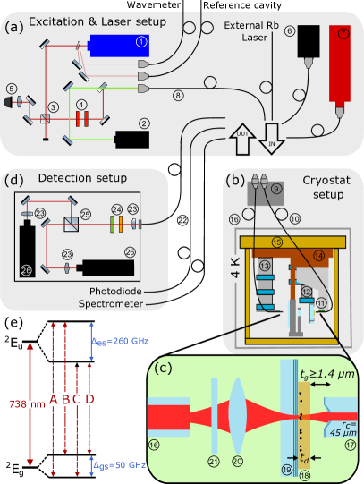
In general, the SM side is used as input and the MM side as output port until stated otherwise. The MM is mounted to a 3D nanopositioner stack222Attocube ANPx101, attocube ANPz102 with position readout for reproducible placement of the fiber into the focus of the lens (Fig. 1d). For coarse microcavity length adjustment and lateral control, the macroscopic mirror is mounted on a second 3D nanopositioner stack333Attocube ANPx311, attocube ANPz51 Casabone et al. (2018). In that way, the plane mirror can be moved several mm away from the cavity fiber tip to avoid crashing the fiber into the mirror during cool down. The base plate of the experimental insert, carrying the microcavity and the nanopositioners is screwed to the base plate of the cryostat insert.
The setup including the cavity and positioning devices is incorporated into a wet - dilution refrigerator444Oxford Kelvinox 100, allowing base temperatures of down to 23 mK. However, we only operate the system as bath cryostat with liquid He since it was not necessary to go to lower temperatures due the spectroscopic properties at 4 K (see Sec. IV). All compressors needed for the operation of the cryostat are external, greatly reducing the vibrational noise in the system. Both sides of the cavity are accessed from outside the cryostat via optical fibers. The PM and MM fiber are guided to the four intermediate temperature stages of the cryostat and are glued with cryogenic varnish for thermal and mechanical anchoring. At the top, the fibers are fed through a press seal to the outside of the cryostat into a home-built fiber breakout box. It provides optical in/out coupling to both sides of the cavity via standard APC connectors for the excitation and SiV- fluorescence light.
The microcavity is probed with a grating-stabilized diode laser555Toptica DL pro design at 737 nm for cavity characterization and resonant excitation of the SiV-. Off-resonant excitation is achieved with a solid-state laser at 532 nm, which lies outside the stopband of the dielectric mirror coating, to enable the excitation of SiV- centers without the need of setting the cavity to be resonant to the laser frequency. To measure the microcavity length and dispersion relation for the incorporated membrane, we employ a compact broadband light source666Thorlabs SLS201L coupled into the cavity. The excitation light is fiber coupled and connected to the breakout box at top of the cryostat. For detection, the output of the microcavity is either fiber-coupled to a photodiode, a grating spectrometer or an avalanche photodiode (APD) (Fig. 1d). Spectral filters in front of the APD detector result in a spectral detection window from 720 nm to 738 nm.
II.1 Characterization of the empty cavity
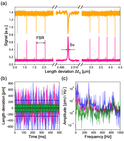
The microcavity shows stable operation in the length range from the radius of curvature of the concave fiber end, µm, determined from interferometric measurements of the fiber profile, down to a minimum length of µm, limited by the depth of the concave profile of the fiber ends facet and the penetration of the light into the mirror stack. This corresponds to a fundamental mode order of with a mode waist of µm, resulting in a mode volume of at 736 nm. We determine the cavity finesse with laser light at 737 nm and scanning the microcavity length. A typical length scan with nine resonances in reflection and transmission can be seen in Fig. 2a. For µm, the finesse settles at , expected from the mirror coating. At longer cavity lengths, diffraction losses lead to a reduced finesse Benedikter et al. (2015). For =10 µm, this finesse corresponds to a quality factor of for the empty cavity.
In order to actively stabilize the cavity length, we employ laser light at 780 nm, as this allows for spectral separation and simultaneous observation the SiV- fluorescence signal. A grating-stabilized diode laser locked on a Rb vapor cell resonance generates a side-of-fringe error signal from the cavity transmission. At 780 nm, the finesse is reduced to about 1000.
With the setup operated at 300 K and µm, a reduction of the temporal length fluctuations from () pm (150% cavity linewidth) to () pm (30% cavity linewidth) is achieved (Fig. 2b). Fig. 2c shows the Fourier spectrum of the cavity length deviation for the unlocked and locked case. The lock shows efficient suppression of noise up to frequencies of about 800 Hz. However, locking the cavity proves itself to be substantially harder at liquid He temperature (from () pm for the unlocked case down to () pm in the locked case at µm), mainly because of a ()-fold increase of vibrational noise at () Hz at 4 K compared to () Hz at 300 K. We conjecture eigenfrequencies of the nanopositioners, ranging at these lower frequencies, to be the reason for large vibration amplitudes.
III Diamond membrane
In this chapter, we present a method to fabricate thin diamond membrane windows with high crystal quality and low surface roughness. This is required to introduce SiV- centers with favorable optical properties, like lifetime limited emission linewidths and long coherence times, into the microcavity, while maintaining a high cavity finesse. Furthermore, the position of the SiV- centers in the diamond needs to match the standing wave field of the cavity mode. This is achieved by the implantation of Si+ atoms with well-defined energy into the crystal.
III.1 Preparation and application
Fabricating the diamond membrane samples involves multiple steps. First, commercial high pressure, high temperature (HPHT) samples777Element Six, Type 1b,
(3.0 3.0 0.3) mm are used as seed substrates to begin the fabrication of the SCD membrane samples.
The substrates are implanted with high energy He ions (1 MeV, 5 1016 ions/cm2) to create an amorphous layer 1.7 µm below the top diamond surface. The implanted samples are subsequently annealed at 1150C for 1 h in vacuum ( 5.0 10-6 torr) to convert the amorphous layer into a graphitic-like etchable layer. A single crystal homo-epitaxial growth was performed on the implanted samples to obtain a high-quality diamond overgrowth of 6 µm.
We then conduct a laser micromachining of a polycrystalline diamond to create supporting scaffolds with micro-channels for membranes, minimizing the risk of breakage and for easier handling. Then, we perform another growth process to fuse the scaffold into the over-grown sample along the contact and an electrochemical etching to lift-off the membrane from the substrate Piracha
et al. (2016a, b). Prior to ICP-RIE888inductively coupled plasma - reactive ion etching processes, the membrane sample is mounted on a glass or Si substrate, such that the lifted-off side faces up. We first use an ArCl2 based plasma to obtain the desired membrane thickness. We subsequently use an O2 based plasma for a short duration ( 3 min) to remove any possible Ar and Cl contaminations Appel et al. (2016).
Si+ implantation is carried out on the membrane windows using a microbeam at an energy of 110 keV with fluences from 4.3 108 to 1.0 1014 ions/cm2, containing 14 circular implantation regions in each window with a diameter of 45 µm. The implantation energy is chosen such that the target depth of the Si+ ions matches the first antinode of the intracavity light field (75 nm, simulated with SRIM999stopping and range of ions in matter Ziegler and Biersack (1985)). The implanted membrane sample is annealed at 1000C for 3 h in vacuum to promote the formation and activation of silicon vacancies Becker et al. (2018). The sample is subsequently acid-cleaned and annealed at 500C in O2 to remove any graphitic layers Tetienne et al. (2018); Fu et al. (2010).
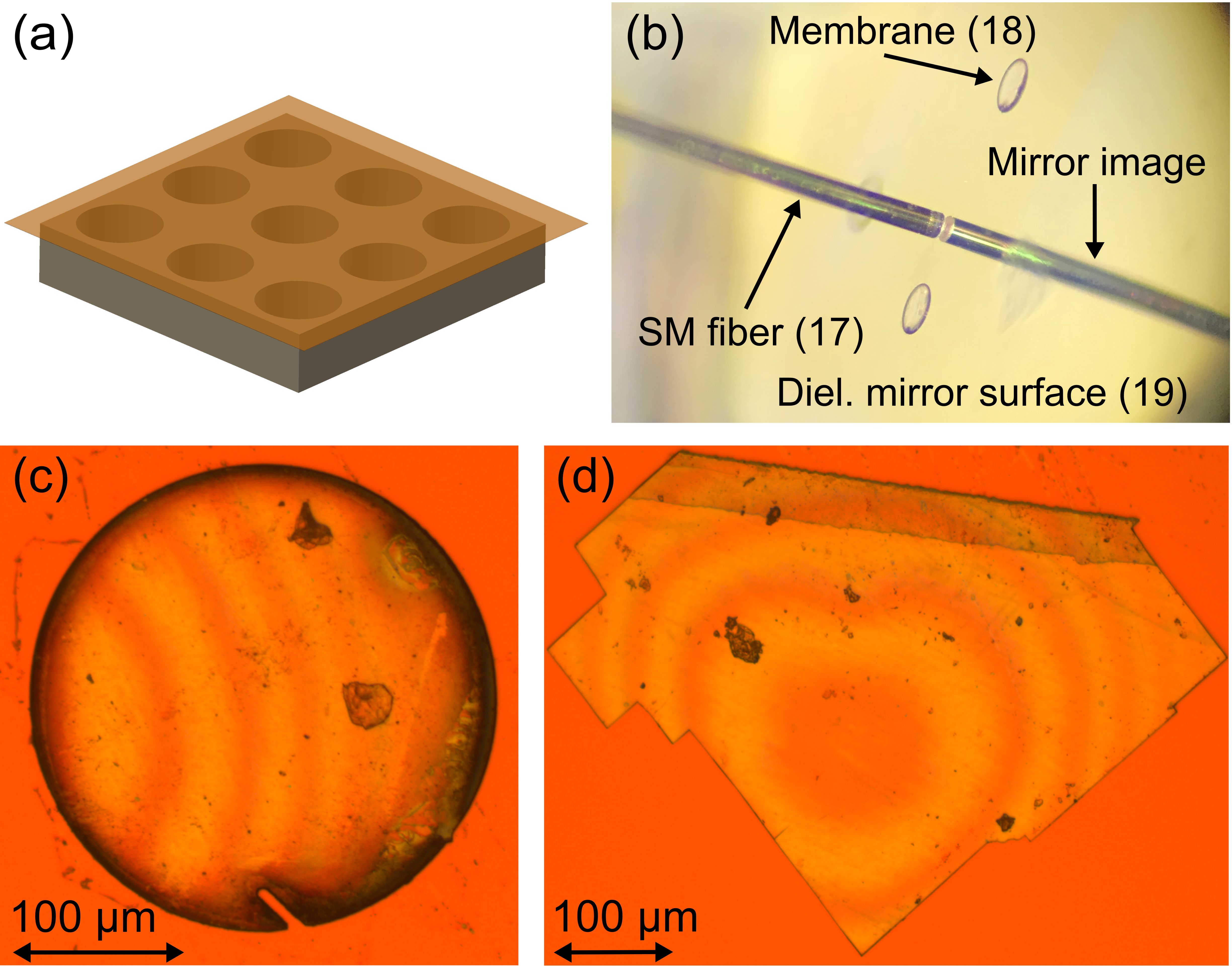
The SiV--implanted membrane windows (Fig. 3a) are laser cut and placed onto a clean Si substrate. The dielectric mirror was cleaned using acetone, methanol, and IPA, followed by an additional 10 min O2 plasma cleaning process, prior to apply membrane windows. Using a water drop on a thin wire attached to a needle, the membrane windows are drawn from Si substrate and transferred to the dielectric mirror (Fig. 3b). However, some carbon debris at the edge of the diamond membrane windows can be seen (Fig. 3c). This debris leads in photoluminescence (PL) measurements (see Sec. IV.1) to a large, broadband background signal due to total internal reflection inside the membrane, even at positions without debris. Hence we investigate in the following only SiV- ensembles present in a broken membrane piece (Fig. 3d). For this sample, an unintended air gap between the membrane and the mirror is found which shifts the coupled modes of the microcavity (see Sec. III.2).
III.2 Integrated membrane-cavity system
Introducing a thin layer of diamond into an optical resonator alters the cavity properties. First, both the surface roughness of the diamond membrane as well as dirt on this surface can lead to additional loss channels of the cavity, potentially reducing the finesse depending on the thickness of the membrane layer van Dam et al. (2018). The transmission of the mirror with the diamond layer attached can be significantly enlarged depending on the thickness of the diamond layer, as it can have a similar effect as an anti-reflective coating layer Janitz et al. (2015). This can drastically reduce the finesse as well as shift the probability of a photon which was emitted into the cavity mode leaving the cavity through the mentioned mirror. Additionally, the resonance conditions of the cavity are shifted.
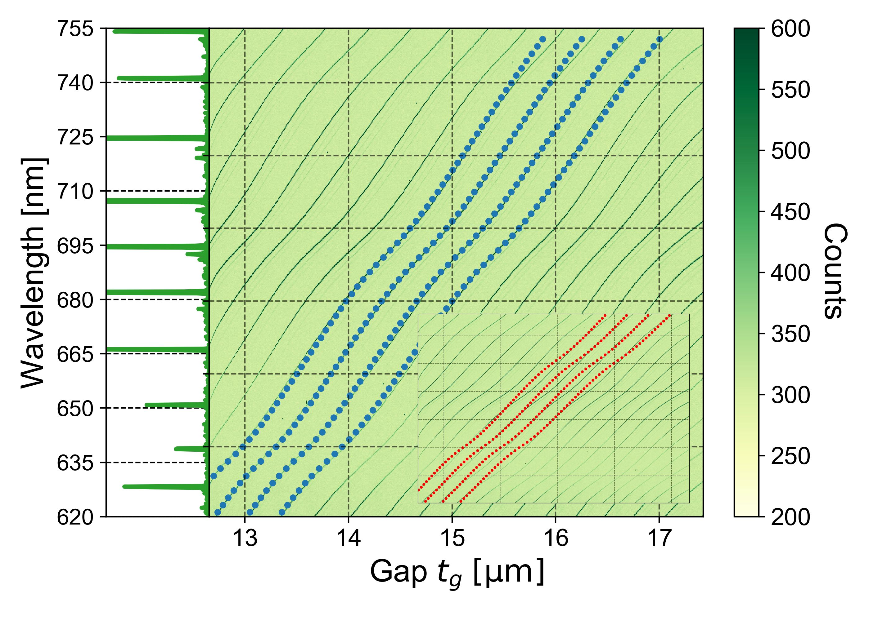
Using an analytic 1D model Janitz et al. (2015), one finds that the cavity resonance frequencies are no longer linearly dependent on the cavity length but a complex dependency in the case of coupled air- and diamond-like modes. We use this model to calculate the diamond thickness and the gap between the diamond membrane and fiber mirror by fitting it to the measured resonance peaks. If we model only the independently determined diamond membrane thickness of (µm, we find bad agreement with the measured data (see inset of Fig. 4). However, if we use a transfer matrix model Janitz et al. (2015), describing both dielectric mirror stacks, sandwiched by a gap, the diamond membrane and a second gap of nm between the plane mirror and the diamond membrane, we find excellent agreement of the calculated resonances with our measured data (Fig. 4). The existence of a parasitic second gap is further confirmed from optical microscopy where we observe interference fringes and a non-perfect van der Waals bonding of the membranes. This is evidenced by a sudden shift of the membrane position when the cavity fiber was approached closely, presumably due to forces from electrostatic charging.
For the fiberbased cavity including the diamond membrane, the measured finesse depends on the exact position of the cavity mode on the diamond membrane.
For the best case, a drop of the finesse down to 70% of the bare cavity finesse is measured. The additional losses of ppm per round trip can be attributed to the diamond membrane. We conjecture the surface roughness of nm as main reason, which would explain additional scattering losses of up to 11700 ppm depending on the diamond thickness and hence the position of the diamond boundary with respect to the cavity mode standing wave field, estimated using an extended transfer matrix model with partially reflective rough interfaces van Dam et al. (2018).
We measure a maximum quality factor of for µm for the cavity including the diamond membrane.
IV Coupling SiV- ensembles to the microcavity
IV.1 Properties of SiV- ensembles in the diamond membrane
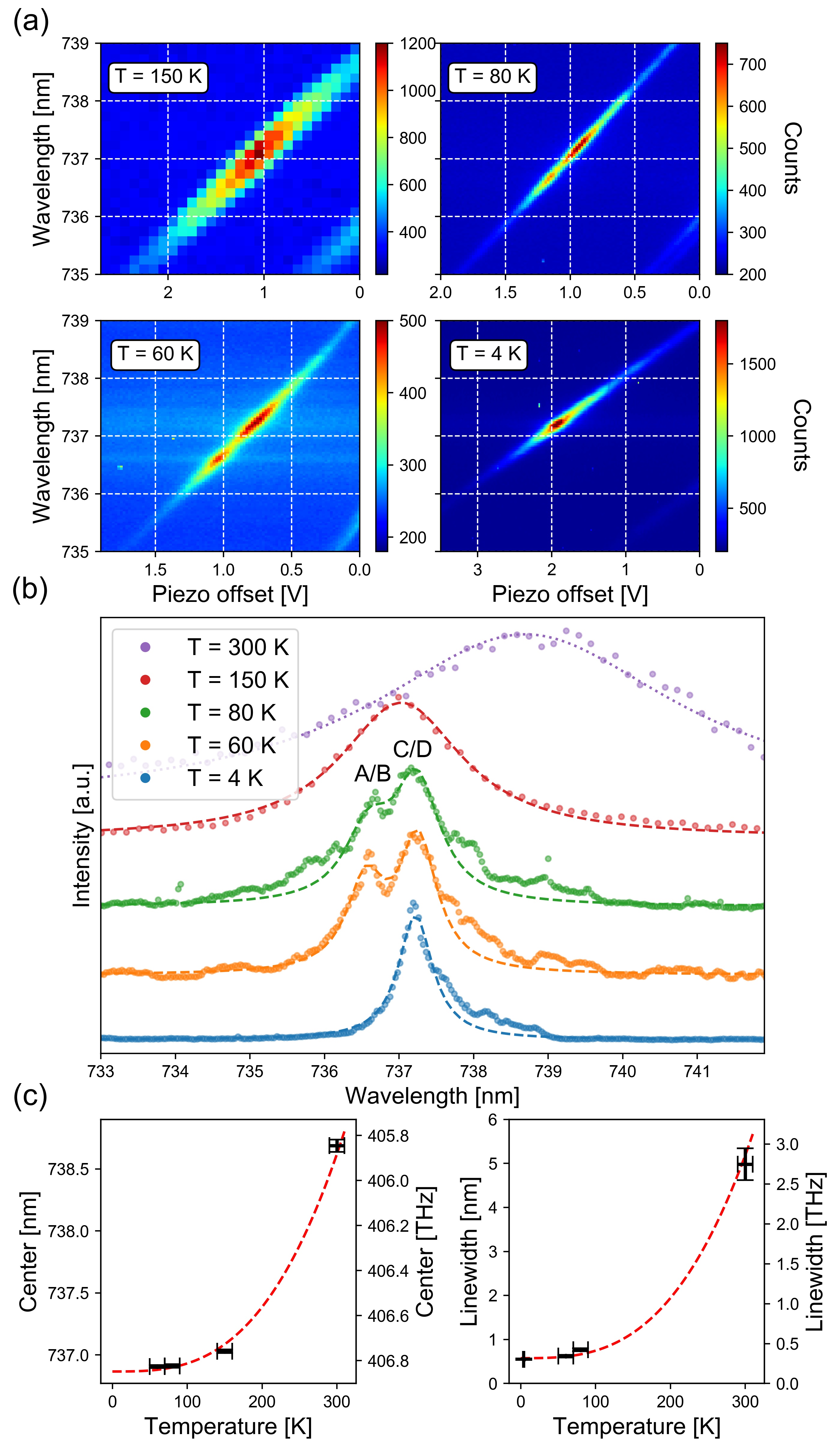
We perform PL spectroscopy on a SiV- ensemble with 532 nm light sent into the cavity via the SM fiber while scanning the cavity resonance frequency over the zero-phonon line (ZPL) and observing the light emitted from the cavity and collected by the MM fiber. This light is spectrally analyzed (see Fig. 5a). In order to study the emission spectrum at different temperatures, we cool the sample down to 4 K with several intermediate steps. Note, that when the cavity is at resonance with the SiV- emission, it merely acts as an efficient light collection system, hence not modifying the shape of the spectrum significantly.
To obtain the full ZPL spectrum, we sum over the SiV- signal emitted into the fundamental cavity mode for the whole cavity length range. The result is shown in Fig. 5b for each temperature. At room temperature, we observe a broad emission peak around 738.7 nm with a linewidth of about 5 nm. At liquid He temperature, the A/B peak vanishes, indicating a strong phononic relaxation into the lower branch of the excited state, possibly due to strain in the diamond crystal Sternschulte et al. (1994); Meesala et al. (2018); Clark et al. (1995). The remaining C/D peak features a linewidth of GHz. We attribute the broader linewidth with respect to earlier findings in bulk diamond Rogers et al. (2014a) to inhomogeneous broadening of the SiV- ensemble due to local strain from Si implantation Evans et al. (2016) as well as mechanical stress induced from improper bonding.
At 60 K and 80 K, the doublet structure is fitted by a double Lorentzian peak function with equal linewidth, resulting in center positions at nm and nm (Fig. 5b). The observed splitting is GHz, neglecting a small dependency of the temperature Jahnke et al. (2015). We interpret the peaks as the A/B and C/D transition in the electronic SiV- level (see Fig. 1e). The ground state splitting into two doublets with an expected value of GHz, respectively, is lower than the inhomogeneous broadening of the ensemble and hence not resolvable. The measured splitting between the two peaks is larger than the combined value for both splittings GHz Hepp et al. (2014).
A possible reason could be strain in the diamond membrane Meesala et al. (2018), due to imperfect bonding caused by the polycrystalline layer between parts of the membrane and the plane mirror (see Fig. 3d) or due to different temperature expansion coefficients of diamond and the mirror substrate.
The mean ZPL center position and linewidth of the SiV- ensemble follow the cubic dependence with decreasing temperature (Fig. 5c) Jahnke et al. (2015). The center fit approaches nm for low temperatures, in good agreement with other findings Jahnke et al. (2015); Meesala et al. (2018), but contradicting the claim of strain present in the diamond crystal.
IV.2 Cavity-induced enhancement of the spontaneous emission rate
Purcell pioneered the enhanced emission of emitters into a cavity mode and the reduction of the excited state lifetime Purcell (1946). For a solid state emitter coupled to an optical microcavity, only the radiative decay into the ZPL, , is enhanced by the cavity, with being the Debye-Waller factor. The total decay rate consists of three contributions , with the non-radiative decay , the radiation into free space , which is approximated by the radiative decay at an absent cavity, and the radiation into the cavity mode , which is modified by the Purcell factor . This results in a reduction of the lifetime by Benedikter et al. (2017)
| (1) |
with the quantum efficiency . The Purcell factor is given by
| (2) |
with being the spatial and directional overlap of the dipole moment with the cavity light field mode, the refractive index of the host material, the effective quality factor, derived by the quality factor of the emitter ensemble and the cavity Meldrum et al. (2010). The cavity mode volume is given by , with the waist of the cavity mode and the effective cavity length , which factors in the diamond membrane and the penetration of the light field into the dielectric mirror stacks, weighted by the local energy density of the light field mode van Dam et al. (2018).
We perform time-correlated single-photon counting after pulsed excitation of the SiV- ensemble to investigate the influence of the cavity on the excited state lifetime of the emitters. The ensemble is excited by a pulsed laser source101010PicoQuant LDH-P-FA-530B at 532 nm via the SM fiber, and the emission is detected via the MM fiber by an avalanche photodiode111111Perkin Elmer SPCM-AQR, after passing several spectral filters. The signal is fed to a time-correlated single photon counting module to record the time trace of the decay of the excited state. All measurements were performed at 77 K temperature in order to grant a homogeneous overlap of the ensemble with the cavity mode. Note that due to the large free spectral range of the microcavity, no significant emission of the ensemble is supported by another cavity mode.
Fig. 6a shows the time trace of detected events after pulsed excitation for the case of the cavity enhancing the transition A/B at an effective cavity length of µm. The time traces were fit using three different models: a mono-exponential decay, a stretched exponential decay function (Kohlrausch function) to take potential multi-exponential decays into account Berberan-Santos
et al. (2005), and a convolution of a Gaussian function with an exponential decay (EMG function) which includes the instrument response function.
The fit results of the mono-exponential and the stretched exponential decay model agree with each other, indicating that multi-exponential decay only plays a negligible role. Furthermore, the absence of bi-exponential decay implies that no collective emitter dynamics are present Temnov and Woggon (2005). The EMG model results give % larger values for the excited state lifetime. We take the minimum and maximum values of the lifetime from the different fit models as a conservative estimate of the uncertainty of the measured lifetime. Note that off-resonant lifetime measurements were not possible due to parasitic background emission of the fibers leading to a low signal-to-noise ratio, caused by dopants and impurities in the glass material of the fiber cables.
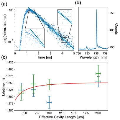
The Purcell factor increases with reduced cavity length (Eq. 2).
To observe this effect in the experiment, we measure the excited state lifetime for varying cavity lengths and set the cavity to be resonant to the A/B and C/D transition, respectively, for each cavity length. The result is shown in Fig. 6c. We fit the data with a model following Eqs. 1 and 2, where is experimentally determined, and are calculated by a coupled Gaussian beams model and the transfer matrix model Janitz et al. (2015); van Dam et al. (2018), is calculated from the electrical field at the implantation depth given by the SRIM simulation, and and are free parameters. The measured data is shown in Fig. 6c, as well as the fit model for the parameters ns, and .
The determined off-resonant lifetime of the ensemble lies in the range of about 1-4 ns of earlier results Rogers et al. (2014a); Jahnke et al. (2015); Neu et al. (2011, 2013); Sternschulte et al. (1994), as well as the quantum efficiency for bulk-like diamond samples Riedrich-Möller
et al. (2014); Zhang et al. (2018). Note, that the fit function can only give a coarse approximation for the quantum efficiency, since it only becomes relevant for small effective cavity lengths. Using the extracted free space lifetime from the fit, we determine a maximum cavity induced lifetime reduction of for the A/B transition and for the C/D transition. We estimate the Purcell factor using the fit parameters together with Eq. 1 to be for the C/D transition at the shortest effective cavity length, only slightly above the threshold of significance, but in agreement with the expected value from Eq. 2: .
V Discussion and Outlook
In this work, we present an experimental apparatus to couple color center ensembles hosted in diamond membranes to a fiberbased microcavity with a small mode volume at temperatures down to 4 K. The setup shows reproducible performance after several thermal cyclings. The design allows for the fast exchange of samples and thus grants flexibility with respect to the color center species Bradac et al. (2019) as well as advances in sample quality. The - dilution refrigerator should enable the cooling of the sample to the mK range, and can further be upgraded to include a vector magnet, allowing both the spectral resolving of the spin qubit and long coherence times for the SiV- qubit Sukachev et al. (2017); Becker et al. (2018), encoded in the Zeeman sublevels of the ground state of the lower branch Rogers et al. (2014b); Pingault et al. (2014).
In future work, we plan to improve the fabrication and treatment of the diamond membrane in order to reduce the residual strain, which is present in the current sample. Off-resonant excitation of the SiV- ensemble with a wavelength closer to the zero-phonon line of the transition and the choice of pure silica core optical fiber cables can be used to decrease background fluorescence of the input and output fibers in order to to detect single emitters. Going to single emitters, the Purcell enhancement can be boosted in multiple ways: The quality factor of an SiV- emitter can be enlarged up to for the lifetime-limited linewidth of 141 MHz by cooling down the sample further. This would make the use of mirror coatings with higher reflectivity useful. Fiberbased optical resonators with finesse values in the range of are feasible with current technology. A more rigid design of the experimental insert Gallego et al. (2016) and advanced locking techniques combined with higher-order low-pass filters in the electronic lock Janitz et al. (2017) circuit should enable the stabilization of cavities with finesse values of about Casabone et al. (2020). This raises the cavity quality factor to for the smallest accessible effective cavity length of about 3.5 µm and therefore boosts the single emitter Purcell factor to about 144 with a near-unit collection efficiency of %, reaching the strong coupling regime.
To measure the properties of color centers without the influence of the microcavity, an additional, non-coated fiber could be implemented into the setup.
Concerning the diamond membrane, a new generation of samples has shown reduced surface roughness values down to nm, which is close to state-of-the-art roughness values reported from 0.3 nm to about 1 nm Janitz et al. (2015); Ruf et al. (2019); Riedel et al. (2020). Using an advanced application technique, based on the controlled transfer of the membrane using a focused ion beam (FIB) device allows for a cleaner and improved bonding, effectively increasing with the incorporated membrane. Lower implantation doses and high temperature annealing can lead to narrow-linewidth homogeneous emitters Evans et al. (2016); Yamamoto et al. (2013); Orwa et al. (2011); Osterkamp et al. (2019).
Acknowledgements: We thank Morgane Gandil, Philipp Fuchs, Elke Neu and Christoph Becher for helpful discussions as well as characterization measurements of the membrane samples. We thank Michael Kieschnick and Jan Meijer for the implantation of Si into the samples. We thank Lachlan J. Rogers and Fedor Jelezko for helpful discussions at the early stages of the experiment. We thank Kumaravelu Ganesan for assistance with membrane samples‘ fabrication. The work was performed in part at the Melbourne Centre for Nanofabrication (MCN) in the Victorian Node of the Australian National Fabrication Facility (ANFF). AN is supported by the Australian Research Council via Linkage Grant LP160101515. Experiments were partly performed using the Qudi software suite Binder et al. (2017). MS, YH, DH and FSK acknowledge financial support by the Bundesministerium für Bildung und Forschung via Q.Link.X. MS, YH and FSK acknowledge financial support by the VolkswagenStiftung.
References
- Fuchs et al. (2018) P. Fuchs, M. Challier, and E. Neu, New Journal of Physics 20, 125001 (2018), doi: 10.1088/1367-2630/aaf0c5.
- Leifgen et al. (2014) M. Leifgen, T. Schröder, F. Gädeke, R. Riemann, V. Métillon, E. Neu, C. Hepp, C. Arend, C. Becher, K. Lauritsen, and O. Benson, New Journal of Physics 16, 023021 (2014), doi: 10.1088/1367-2630/16/2/023021.
- Humphreys et al. (2018) P. C. Humphreys, N. Kalb, J. P. J. Morits, R. N. Schouten, R. F. L. Vermeulen, D. J. Twitchen, M. Markham, and R. Hanson, Nature 558, 268 (2018), doi: 10.1038/s41586-018-0200-5.
- Nguyen et al. (2019a) C. Nguyen, D. Sukachev, M. Bhaskar, B. Machielse, D. Levonian, E. Knall, P. Stroganov, R. Riedinger, H. Park, M. Lončar, and M. Lukin, Physical Review Letters 123 (2019a), doi: 10.1103/physrevlett.123.183602.
- Bradley et al. (2019) C. Bradley, J. Randall, M. Abobeih, R. Berrevoets, M. Degen, M. Bakker, M. Markham, D. Twitchen, and T. Taminiau, Physical Review X 9 (2019), doi: 10.1103/physrevx.9.031045.
- Maurer et al. (2012) P. C. Maurer, G. Kucsko, C. Latta, L. Jiang, N. Y. Yao, S. D. Bennett, F. Pastawski, D. Hunger, N. Chisholm, M. Markham, D. J. Twitchen, J. I. Cirac, and M. D. Lukin, Science 336, 1283 (2012), doi: 10.1126/science.1220513.
- Bar-Gill et al. (2013) N. Bar-Gill, L. Pham, A. Jarmola, D. Budker, and R. Walsworth, Nature Communications 4 (2013), doi: 10.1038/ncomms2771.
- Sukachev et al. (2017) D. Sukachev, A. Sipahigil, C. Nguyen, M. Bhaskar, R. Evans, F. Jelezko, and M. Lukin, Physical Review Letters 119 (2017), doi: 10.1103/physrevlett.119.223602.
- Iwasaki et al. (2015) T. Iwasaki, F. Ishibashi, Y. Miyamoto, Y. Doi, S. Kobayashi, T. Miyazaki, K. Tahara, K. D. Jahnke, L. J. Rogers, B. Naydenov, F. Jelezko, S. Yamasaki, S. Nagamachi, T. Inubushi, N. Mizuochi, and M. Hatano, Scientific Reports 5 (2015), doi: 10.1038/srep12882.
- Trusheim et al. (2020) M. E. Trusheim, B. Pingault, N. H. Wan, M. Gündoğan, L. D. Santis, R. Debroux, D. Gangloff, C. Purser, K. C. Chen, M. Walsh, J. J. Rose, J. N. Becker, B. Lienhard, E. Bersin, I. Paradeisanos, G. Wang, D. Lyzwa, A. R.-P. Montblanch, G. Malladi, H. Bakhru, et al., Physical Review Letters 124 (2020), doi: 10.1103/physrevlett.124.023602.
- Robledo et al. (2011) L. Robledo, L. Childress, H. Bernien, B. Hensen, P. F. A. Alkemade, and R. Hanson, Nature 477, 574 (2011), doi: 10.1038/nature10401.
- Hadden et al. (2010) J. P. Hadden, J. P. Harrison, A. C. Stanley-Clarke, L. Marseglia, Y.-L. D. Ho, B. R. Patton, J. L. O’Brien, and J. G. Rarity, Applied Physics Letters 97, 241901 (2010), doi: 10.1063/1.3519847.
- Maletinsky et al. (2012) P. Maletinsky, S. Hong, M. S. Grinolds, B. Hausmann, M. D. Lukin, R. L. Walsworth, M. Loncar, and A. Yacoby, Nature Nanotechnology 7, 320 (2012), doi: 10.1038/nnano.2012.50.
- Mouradian et al. (2015) S. L. Mouradian, T. Schröder, C. B. Poitras, L. Li, J. Goldstein, E. H. Chen, M. Walsh, J. Cardenas, M. L. Markham, D. J. Twitchen, M. Lipson, and D. Englund, Physical Review X 5 (2015), doi: 10.1103/physrevx.5.031009.
- Zhang et al. (2018) J. L. Zhang, S. Sun, M. J. Burek, C. Dory, Y.-K. Tzeng, K. A. Fischer, Y. Kelaita, K. G. Lagoudakis, M. Radulaski, Z.-X. Shen, N. A. Melosh, S. Chu, M. Lončar, and J. Vučković, Nano Letters 18, 1360 (2018), doi: 10.1021/acs.nanolett.7b05075.
- Riedrich-Möller et al. (2014) J. Riedrich-Möller, C. Arend, C. Pauly, F. Mücklich, M. Fischer, S. Gsell, M. Schreck, and C. Becher, Nano Letters 14, 5281 (2014), doi: 10.1021/nl502327b, pMID: 25111134, eprint http://dx.doi.org/10.1021/nl502327b.
- Romagnoli et al. (2020) P. Romagnoli, M. Maeda, J. M. Ward, V. G. Truong, and S. N. Chormaic, Applied Physics B 126 (2020), doi: 10.1007/s00340-020-07456-x.
- Albrecht et al. (2013) R. Albrecht, A. Bommer, C. Deutsch, J. Reichel, and C. Becher, Physical Review Letters 110 (2013), doi: 10.1103/physrevlett.110.243602.
- Riedel et al. (2017) D. Riedel, I. Söllner, B. J. Shields, S. Starosielec, P. Appel, E. Neu, P. Maletinsky, and R. J. Warburton, Physical Review X 7 (2017), doi: 10.1103/physrevx.7.031040.
- Kaupp et al. (2016) H. Kaupp, T. Hümmer, M. Mader, B. Schlederer, J. Benedikter, P. Haeusser, H.-C. Chang, H. Fedder, T. W. Hänsch, and D. Hunger, Physical Review Applied 6 (2016), doi: 10.1103/physrevapplied.6.054010.
- Häußler et al. (2019) S. Häußler, J. Benedikter, K. Bray, B. Regan, A. Dietrich, J. Twamley, I. Aharonovich, D. Hunger, and A. Kubanek, Physical Review B 99 (2019), doi: 10.1103/physrevb.99.165310.
- Nair et al. (2019) S. R. Nair, L. J. Rogers, X. Vidal, R. P. Roberts, H. Abe, T. Ohshima, T. Yatsui, A. D. Greentree, J. Jeske, and T. Volz, arXiv:1912.05801 (2019), eprint https://arxiv.org/abs/1912.05801.
- Nguyen et al. (2019b) C. T. Nguyen, D. D. Sukachev, M. K. Bhaskar, B. Machielse, D. S. Levonian, E. N. Knall, P. Stroganov, C. Chia, M. J. Burek, R. Riedinger, H. Park, M. Lončar, and M. D. Lukin, Physical Review B 100 (2019b), doi: 10.1103/physrevb.100.165428.
- Colombe et al. (2007) Y. Colombe, T. Steinmetz, G. Dubois, F. Linke, D. Hunger, and J. Reichel, Nature 450, 272 (2007), ISSN 0028-0836.
- Gallego et al. (2018) J. Gallego, W. Alt, T. Macha, M. Martinez-Dorantes, D. Pandey, and D. Meschede, Physical Review Letters 121 (2018), doi: 10.1103/physrevlett.121.173603.
- Brandstätter et al. (2013) B. Brandstätter, A. McClung, K. Schüppert, B. Casabone, K. Friebe, A. Stute, P. O. Schmidt, C. Deutsch, J. Reichel, R. Blatt, and T. E. Northup, Review of Scientific Instruments 84, 123104 (2013), doi: http://dx.doi.org/10.1063/1.4838696.
- Meyer et al. (2015) H. M. Meyer, R. Stockill, M. Steiner, C. Le Gall, C. Matthiesen, E. Clarke, A. Ludwig, J. Reichel, M. Atatüre, and M. Köhl, Phys. Rev. Lett. 114, 123001 (2015), doi: 10.1103/PhysRevLett.114.123001.
- Pfister et al. (2016) A. D. Pfister, M. Salz, M. Hettrich, U. G. Poschinger, and F. Schmidt-Kaler, Applied Physics B 122, 1 (2016), doi: 10.1007/s00340-016-6362-7, ISSN 1432-0649.
- Muller et al. (2009) A. Muller, E. B. Flagg, M. Metcalfe, J. Lawall, and G. S. Solomon, Applied Physics Letters 95, 173101 (2009), doi: 10.1063/1.3245311.
- Benedikter et al. (2017) J. Benedikter, H. Kaupp, T. Hümmer, Y. Liang, A. Bommer, C. Becher, A. Krueger, J. M. Smith, T. W. Hänsch, and D. Hunger, Phys. Rev. Applied 7, 024031 (2017), doi: 10.1103/PhysRevApplied.7.024031.
- Lindner et al. (2018) S. Lindner, A. Bommer, A. Muzha, A. Krueger, L. Gines, S. Mandal, O. Williams, E. Londero, A. Gali, and C. Becher, New Journal of Physics 20, 115002 (2018), doi: 10.1088/1367-2630/aae93f.
- Ruf et al. (2019) M. Ruf, M. IJspeert, S. van Dam, N. de Jong, H. van den Berg, G. Evers, and R. Hanson, Nano Letters 19, 3987 (2019), doi: 10.1021/acs.nanolett.9b01316.
- Hunger et al. (2012) D. Hunger, C. Deutsch, R. J. Barbour, R. J. Warburton, and J. Reichel, AIP Advances 2, 012119 (2012), doi: https://doi.org/10.1063/1.3679721.
- Casabone et al. (2018) B. Casabone, J. Benedikter, T. Hümmer, F. Oehl, K. de Oliveira Lima, T. W. Hänsch, A. Ferrier, P. Goldner, H. de Riedmatten, and D. Hunger, New Journal of Physics 20, 095006 (2018), doi: 10.1088/1367-2630/aadf68.
- Benedikter et al. (2015) J. Benedikter, T. Hümmer, M. Mader, B. Schlederer, J. Reichel, T. W. Hänsch, and D. Hunger, New Journal of Physics 17, 053051 (2015), doi: https://doi.org/10.1088/1367-2630/17/5/053051.
- Piracha et al. (2016a) A. H. Piracha, K. Ganesan, D. W. M. Lau, A. Stacey, L. P. McGuinness, S. Tomljenovic-Hanic, and S. Prawer, Nanoscale 8, 6860 (2016a), doi: https://doi.org/10.1039/c5nr08348f.
- Piracha et al. (2016b) A. H. Piracha, P. Rath, K. Ganesan, S. Kühn, W. H. P. Pernice, and S. Prawer, Nano Letters 16, 3341 (2016b), doi: https://doi.org/10.1021/acs.nanolett.6b00974.
- Appel et al. (2016) P. Appel, E. Neu, M. Ganzhorn, A. Barfuss, M. Batzer, M. Gratz, A. Tschöpe, and P. Maletinsky, Review of Scientific Instruments 87, 063703 (2016), doi: https://doi.org/10.1063/1.4952953.
- Ziegler and Biersack (1985) J. F. Ziegler and J. P. Biersack, in Treatise on Heavy-Ion Science (Springer US, 1985), pp. 93–129.
- Becker et al. (2018) J. N. Becker, B. Pingault, D. Groß, M. Gündoğan, N. Kukharchyk, M. Markham, A. Edmonds, M. Atatüre, P. Bushev, and C. Becher, Physical Review Letters 120 (2018), doi: https://doi.org/10.1103/physrevlett.120.053603.
- Tetienne et al. (2018) J.-P. Tetienne, R. W. de Gille, D. A. Broadway, T. Teraji, S. E. Lillie, J. M. McCoey, N. Dontschuk, L. T. Hall, A. Stacey, D. A. Simpson, and L. C. L. Hollenberg, Physical Review B 97 (2018), doi: 10.1103/physrevb.97.085402.
- Fu et al. (2010) K.-M. C. Fu, C. Santori, P. E. Barclay, and R. G. Beausoleil, Applied Physics Letters 96, 121907 (2010), doi: 10.1063/1.3364135.
- van Dam et al. (2018) S. B. van Dam, M. Ruf, and R. Hanson, New Journal of Physics 20, 115004 (2018), doi: https://doi.org/10.1088/1367-2630/aaec29.
- Janitz et al. (2015) E. Janitz, M. Ruf, M. Dimock, A. Bourassa, J. Sankey, and L. Childress, Physical Review A 92 (2015), doi: https://doi.org/10.1103/physreva.92.043844.
- Sternschulte et al. (1994) H. Sternschulte, K. Thonke, R. Sauer, P. C. Münzinger, and P. Michler, Physical Review B 50, 14554 (1994), doi: 10.1103/physrevb.50.14554.
- Meesala et al. (2018) S. Meesala, Y.-I. Sohn, B. Pingault, L. Shao, H. A. Atikian, J. Holzgrafe, M. Gündoğan, C. Stavrakas, A. Sipahigil, C. Chia, R. Evans, M. J. Burek, M. Zhang, L. Wu, J. L. Pacheco, J. Abraham, E. Bielejec, M. D. Lukin, M. Atatüre, and M. Lončar, Physical Review B 97 (2018), doi: 10.1103/physrevb.97.205444.
- Clark et al. (1995) C. D. Clark, H. Kanda, I. Kiflawi, and G. Sittas, Physical Review B 51, 16681 (1995), doi: 10.1103/physrevb.51.16681.
- Rogers et al. (2014a) L. Rogers, K. Jahnke, T. Teraji, L. Marseglia, C. Müller, B. Naydenov, H. Schauffert, C. Kranz, J. Isoya, L. McGuinness, and F. Jelezko, Nature Communications 5, 4739 (2014a), doi: 10.1038/ncomms5739.
- Evans et al. (2016) R. E. Evans, A. Sipahigil, D. D. Sukachev, A. S. Zibrov, and M. D. Lukin, Physical Review Applied 5 (2016), doi: 10.1103/physrevapplied.5.044010.
- Jahnke et al. (2015) K. D. Jahnke, A. Sipahigil, J. M. Binder, M. W. Doherty, M. Metsch, L. J. Rogers, N. B. Manson, M. D. Lukin, and F. Jelezko, New Journal of Physics 17, 043011 (2015), doi: https://doi.org/10.1088/1367-2630/17/4/043011.
- Hepp et al. (2014) C. Hepp, T. Müller, V. Waselowski, J. N. Becker, B. Pingault, H. Sternschulte, D. Steinmüller-Nethl, A. Gali, J. R. Maze, M. Atatüre, and C. Becher, Physical Review Letters 112 (2014), doi: 10.1103/physrevlett.112.036405.
- Purcell (1946) E. M. Purcell, Phys. Rev. 69, 681 (1946), doi: https://doi.org/10.1103/PhysRev.69.674.2.
- Meldrum et al. (2010) A. Meldrum, P. Bianucci, and F. Marsiglio, Optics Express 18, 10230 (2010), doi: 10.1364/oe.18.010230.
- Berberan-Santos et al. (2005) M. Berberan-Santos, E. Bodunov, and B. Valeur, Chemical Physics 315, 171 (2005), doi: 10.1016/j.chemphys.2005.04.006.
- Temnov and Woggon (2005) V. V. Temnov and U. Woggon, Physical Review Letters 95 (2005), doi: 10.1103/physrevlett.95.243602.
- Neu et al. (2011) E. Neu, D. Steinmetz, J. Riedrich-Möller, S. Gsell, M. Fischer, M. Schreck, and C. Becher, New Journal of Physics 13, 025012 (2011), doi: 10.1088/1367-2630/13/2/025012.
- Neu et al. (2013) E. Neu, C. Hepp, M. Hauschild, S. Gsell, M. Fischer, H. Sternschulte, D. Steinmüller-Nethl, M. Schreck, and C. Becher, New Journal of Physics 15, 043005 (2013), doi: 10.1088/1367-2630/15/4/043005.
- Bradac et al. (2019) C. Bradac, W. Gao, J. Forneris, M. E. Trusheim, and I. Aharonovich, Nature Communications 10 (2019), doi: 10.1038/s41467-019-13332-w.
- Rogers et al. (2014b) L. J. Rogers, K. D. Jahnke, M. H. Metsch, A. Sipahigil, J. M. Binder, T. Teraji, H. Sumiya, J. Isoya, M. D. Lukin, P. Hemmer, and F. Jelezko, Physical Review Letters 113 (2014b), doi: 10.1103/physrevlett.113.263602.
- Pingault et al. (2014) B. Pingault, J. N. Becker, C. H. Schulte, C. Arend, C. Hepp, T. Godde, A. I. Tartakovskii, M. Markham, C. Becher, and M. Atatüre, Physical Review Letters 113 (2014), doi: 10.1103/physrevlett.113.263601.
- Gallego et al. (2016) J. Gallego, S. Ghosh, S. K. Alavi, W. Alt, M. Martinez-Dorantes, D. Meschede, and L. Ratschbacher, Applied Physics B 122 (2016), doi: https://doi.org/10.1007/s00340-015-6281-z.
- Janitz et al. (2017) E. Janitz, M. Ruf, Y. Fontana, J. Sankey, and L. Childress, Optics Express 25, 20932 (2017), doi: 10.1364/oe.25.020932.
- Casabone et al. (2020) B. Casabone, C. Deshmukh, S. Liu, D. Serrano, A. Ferrier, T. Hümmer, P. Goldner, D. Hunger, and H. de Riedmatten, arXiv:2001.08532 (2020), eprint http://arxiv.org/abs/2001.08532v1.
- Riedel et al. (2020) D. Riedel, S. Flågan, P. Maletinsky, and R. J. Warburton, Physical Review Applied 13 (2020), doi: 10.1103/physrevapplied.13.014036.
- Yamamoto et al. (2013) T. Yamamoto, T. Umeda, K. Watanabe, S. Onoda, M. L. Markham, D. J. Twitchen, B. Naydenov, L. P. McGuinness, T. Teraji, S. Koizumi, F. Dolde, H. Fedder, J. Honert, J. Wrachtrup, T. Ohshima, F. Jelezko, and J. Isoya, Physical Review B 88 (2013), doi: 10.1103/physrevb.88.075206.
- Orwa et al. (2011) J. O. Orwa, C. Santori, K. M. C. Fu, B. Gibson, D. Simpson, I. Aharonovich, A. Stacey, A. Cimmino, P. Balog, M. Markham, D. Twitchen, A. D. Greentree, R. G. Beausoleil, and S. Prawer, Journal of Applied Physics 109, 083530 (2011), doi: 10.1063/1.3573768.
- Osterkamp et al. (2019) C. Osterkamp, M. Mangold, J. Lang, P. Balasubramanian, T. Teraji, B. Naydenov, and F. Jelezko, Scientific Reports 9 (2019), doi: 10.1038/s41598-019-42314-7.
- Binder et al. (2017) J. M. Binder, A. Stark, N. Tomek, J. Scheuer, F. Frank, K. D. Jahnke, C. Müller, S. Schmitt, M. H. Metsch, T. Unden, T. Gehring, A. Huck, U. L. Andersen, L. J. Rogers, and F. Jelezko, SoftwareX 6, 85 (2017), doi: 10.1016/j.softx.2017.02.001.