UAV Aided Search and Rescue Operation Using Reinforcement Learning ††thanks: This work is supported by NSF under the awards CNS-1453678 and CNS-1916766.
Abstract
Owing to the enhanced flexibility in deployment and decreasing costs of manufacturing, the demand for unmanned aerial vehicles (UAVs) is expected to soar in the upcoming years. In this paper, we explore a UAV aided search and rescue (SAR) operation in indoor environments, where the GPS signals might not be reliable. We consider a SAR scenario where the UAV tries to locate a victim trapped in an indoor environment by sensing the RF signals emitted from a smart device owned by the victim. To locate the victim as fast as possible, we leverage tools from reinforcement learning (RL). Received signal strength (RSS) at the UAV depends on the distance from the source, indoor shadowing and fading parameters, and antenna radiation pattern of the receiver mounted on the UAV. To make our analysis more realistic, we model two indoor scenarios with different dimensions using a commercial ray tracing software. Then, the corresponding RSS values at each possible discrete UAV location are extracted and used in a Q-learning framework. Unlike the traditional location-based navigation approach that exploits GPS coordinates, our method uses the RSS to define the states and rewards of the RL algorithm. We compare the performance of the proposed method where directional and omnidirectional antennas are used. The results reveal that the use of directional antennas provides faster convergence rates than the omnidirectional antennas.
Index Terms:
Directional antenna, drone, Q-learning, navigation, ray tracing, RSS, unmanned aerial vehicle (UAV).I Introduction
Due to their ease of deployment, high flexibility, and low manufacturing cost, drones or unmanned aerial vehicles (UAVs) can be deployed in various civilian applications, including but not limited to precision agriculture, cleaning up ocean waste, packet delivery, restoring wireless service after natural disasters, and search and rescue (SAR) operations [1, 2, 3, 4, 5]. It is estimated that the market for commercial UAVs will reach a multi billion U.S. dollars by the year 2025 [6]. Hence, a huge amount of efforts in both academia and industry have been devoted to different aspects of UAV applications.
SAR operations occur during or after natural disasters, finding missing persons, accidents, evacuation process to provide immediate help. These operations are time-critical and proven to be effective when the operation is completed in the shortest possible time. These operations can take place where human access may not be possible. Thanks to their flexibility in deploying, UAVs are suitable for such scenarios and hence, can aid interaction to inaccessible or unapproachable environments for humans [7]. However, due to the lack of a reliable communication link between the UAV and the controller or technical requirements beyond human capabilities, human control over the UAVs may not always be possible [8]. Hence, it is critically important to develop effective yet accurate algorithms to enable the UAVs to perform complicated tasks without human interaction. Note that in the case of SAR operations, most of the time, the prior knowledge pertinent to the environment is limited, if not completely unavailable. Furthermore, the environment in interest can change abruptly or the models defining the victim’s locations may not be accurate. Hence, the autonomous UAV deployed in the SAR operation can interact with the environment for taking decisions by itself. In such a case, a subclass of machine learning called reinforcement learning (RL), which does not require any prior knowledge of the environment, may help to overcome these issues.
In a typical RL algorithm, the agent learns how to act properly in an unknown environment by repetitive interaction with that particular environment [9]. The environment is usually modeled as a Markov decision process (MDP), and a dynamic programming (DP) technique is used to find the optimum set of sequential actions or the optimum policy [10]. However, to utilize the DP technique, the complete knowledge of the environment is required to be known beforehand. On the contrary, a branch of RL, known as Q-learning, does not require such explicit knowledge of the environment. Q-learning is an off-policy RL algorithm which aims to find the best policy for maximizing total discounted future reward in an unknown environment given the current state [9].
RL-based algorithms have already been studied in UAV-related researches such as robotics, wireless communication, etc [11, 12]. The authors in [11] explore both traditional table-based and neural network-based Q-learning to provide better connectivity in a downlink cellular network. In [12], a model-based RL algorithm is used for the autonomous navigation of UAVs, which learns faster than the traditional table-based Q-learning due to its parallel architecture. In [2], a function approximation-based RL approach is exploited for a large number of states. The use of function approximation reduces the convergence time of the algorithm needed for a SAR operation. This approach also considers the obstacle avoidance needed by an agent to avoid a collision in the environment. The results were proved using simulation as well as real-time implementation. In [13], the authors implement a SAR operation for a fully autonomous robotic solution in unstructured indoor environments. The target recognition uses a supervised learning approach for target background classification. The study in [14] uses deep deterministic policy gradients to provide results in continuous time and action. It also uses a framework that makes sure that the UAV uses a collision-free path to reach the target. The UAV not only focuses on rewards, but also considers the punishment irrespective of the action taken. The use of neural networks and deep learning was briefly performed in [15]. This is an embedded system-based approach that guarantees safe take-off, navigation, and landing of the UAV on a fixed target. .
In a recent study, the authors propose a SAR method by exploiting the RF signal emitted from the devices owned by a victim [4]. They also provide a comparison between the location-based and received signal strength (RSS)-based approach using an omnidirectional antenna for an indoor scenario. In this approach, the target’s location, as well as the environment, are unknown to the agent, whereas for the location-based approach, the target position and the UAV’s instantaneous location are known based on which the agent rescues the target. The comparison also proves that the learning phase of the RSS-based approach has lesser fluctuations in training the agent than that in the location-based technique. Since the directional antenna has greater gain in a concentrated direction, it can be more effective to find targets in areas with weak signal power. The directional antenna also provides a larger coverage area, better isolation, and lesser feedback loops. The direction in which the UAV receives the most powerful signal helps understand the probable location of the target. Note that the GPS signals in an indoor environment might not be reliable and hence, the RSS-based indoor navigation is a competitive candidate for SAR missions in indoor scenarios as shown by the authors in [4].
Motivated by the above references, we propose a Q-learning based SAR operation method with the presence of directional antennas both at the UAV and the victim’s device by sensing the RSS emitted from the victim’s device. In case of emergencies, UAV can also force the smart-device to transmit wireless signals [16, 17]. It is also of critical importance to ensure that the UAV reaches the target as soon as possible without colliding with any of the obstacles present in the environment. The UAV in interest senses the RF signals which are emitted intermittently from the victim to navigate through the indoor environment. Prior knowledge of the environment and the location of the victim are not known, and no training set is available for the UAV to map a particular action set to the reward or punishment. The RSS values at different indoor locations can be used by the UAV to take actions to reach the target device without having prior knowledge of the environment. Initially, there is no presence of past experiences or rewards and punishments based on which the UAV can take actions. The Q-learning algorithm uses a Q-table and includes flags for punishment and reward. These flags were updated on every move, which, in turn, generate a Q-table for the UAV from its own actions. As the Q-table gets updated at each iteration, the probability of taking a good action will improve, leading to a faster approach to the target device.

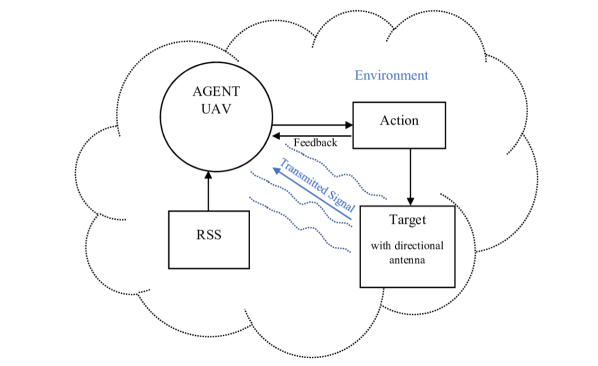
A high-level view of our proposed SAR operation is depicted in Fig. 1. The agent or the UAV takes actions in an indoor environment depending on the RSS, which is obtained from the RF signals transmitted by the victim. A unique state label is assigned to the RSS value at the current UAV position as done in [4]. Based on its current state, the UAV chooses an action in different directions separated by to reach the next location, and this process goes on until the UAV finds the victim. The result of the action taken by the agent is given in the form of feedback. This feedback is either a reward or punishment. A ray tracing software is used to create two different indoor environments that involve obstacles in the form of doorways, windows, and indoor walls. After simulating in the ray tracing software, the obtained RSS values are used as an input to generate a heat map in MATLAB, which is used to define both the states and the rewards. The proposed method was compared to the results obtained using an omnidirectional antenna in terms of the convergence time and the number of steps taken to reach the victim.
The remainder of this paper is organized as follows. Section II provides a brief background on Q-learning while Section III discusses the antenna radiation patterns associated with both directional and omnidirectional antennas. Section IV introduces the simulation setup. Section V gives a brief description of the navigation of the UAV in the indoor environments used. The simulation results of the proposed SAR operation are presented in Section VI, and finally, the paper is concluded in Section VII.
II Background on Q-Learning
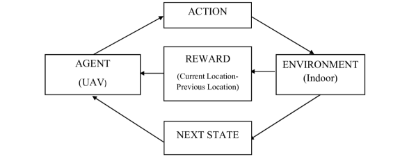
As stated earlier, RL involves interaction between an active decision-making agent and its environment, within which the agent seeks to maximize the future reward despite the uncertainty associated with the environment. An RL agent interacts with the environment in the form of discrete time steps. At each time step, the actions taken by the agent determine the future states, thereby affecting the options and opportunities available to the agent at later times. Correct choice requires considering indirect, delayed consequences of actions, and thus may require foresight or planning. The training phase allows the agent to gain this foresight that helps the agent attain its final goal efficiently with high accuracy. Through repeated action selections, the agent can maximize winnings by concentrating the actions on the best value which is obtained from the options available at a particular time step. If the agent maintains the estimates of the action values, then at any time step there is at least one action whose estimated value is the greatest. Fig. 2 illustrates an example of the interaction between the agent and the environment.
If a greedy action is selected, it is said that the agent is exploiting current knowledge of the values of the actions. If instead the agent selects one of the non greedy actions, then we say it is exploring, because this enables the agent to improve the estimate of the non greedy action’s value. On one hand, exploitation is the right thing to do to maximize the expected reward, while on the other hand, exploration may produce greater total reward in the long run. Thus, using the greedy policy will not allow the agent to explore at all. In order to still allow some exploration, an -greedy policy is used. This involves selection of an action (or one of the actions) with highest estimated action value, that is, to select one of the greedy actions at some time step . Value at the current state in the Q-table is calculated as reward plus the value at the next state. This value is updated in the Q-table. Q-learning is a temporal difference method in which we measure all outcomes at the next state to get an estimate of the value at the current state. It learns by interacting with the environment and approximates a value function of each state-action pair through a number of iterations. The goal is to select the action which has the maximum -value using the following update rule at each iteration:
| (1) |
where is the action taken at time , represents the state reached from state after action is taken, is the learning rate, is the reward attained at current state and is the discount factor. After the iterative process, the agent will eventually learn the optimal Q-values for each state-action pair, over time. The actions with the highest Q-values for each state represent the optimal policy. In other words, the optimal policy can be obtained by acting greedily in every state by
| (2) |

III Background on Antenna Radiation
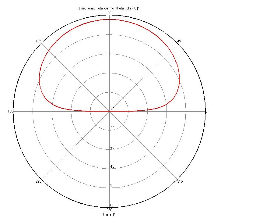
In this section, we discuss the antenna radiation patterns for omnidirectional and directional antennas which are used by the UAV to find the RSS at each receiver grid. The radiation pattern is defined as the mathematical function of the radiation properties of an antenna as a function of space coordinates. The radiation pattern also provides insight into characteristics like flux density, field strength, directivity, and polarization. A graph of variation of power density amplitude along a constant radius is a power pattern and a trace of the received electric field, magnitude at a constant radius is the field pattern.
A radiation lobe is a portion of the radiation pattern within a given area [18]. From Fig. 3, we can see that the omnidirectional antenna has two main lobes and transmits the power in all directions. On the other hand, for the directional antenna, we see only one main lobe, and the transmitted power is concentrated in a specific direction. Directivity is defined as a ratio of radiation intensity in a given direction to the radiation intensity averaged over all directions [18]. In weak signal environments, received signal power is concentrated in specific directions, making directional antenna a better choice for our RSS-based SAR scenario.
IV Simulation Setup
In this section, we discuss the simulation environment modeling for testing our proposed method. The simulation environments used in this study are modeled by using the Wireless InSite ray tracing tool. This software can provide RSS values at each point in an indoor scenario. We have generated two arbitrary indoor floor plans with diverse obstacles. Table I provides a brief summary of all the floor plans used along with the presence of obstacles.
| Floor plan 1 | Floor plan 2 | |
| Dimensions | () | () |
| Doors | 1 | 1 |
| Windows | 2 | 0 |
| Walls | 7 | 10 |
| Victim position | (45 m, 90 m) | (38 m, 27 m) |
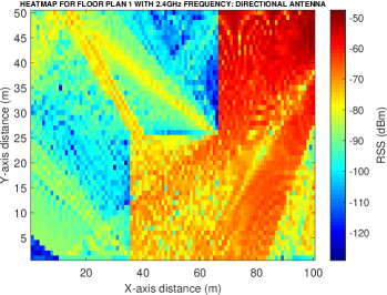
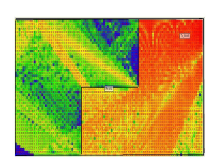
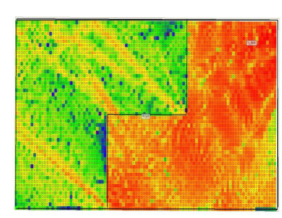
In these floor plans, we have considered walls with a height of 3 m. After generating the floor plans, we run the ray tracing simulations to obtain the RSS at each receiver (RX) grid with the source being stable at a specified position. The RX grid points are set 1 m apart from each other using the XY grid option in the software. It was assumed that the victim transmitted RF signals using 25 dBm transmit power at 2.4 GHz. Directional antenna was used at the transmitter. The maximum antenna gain was considered as 0 dB for both the receiver grid and transmitter[19]. We created the same floor plans in MATLAB and transferred the resulting RSS maps from the ray tracing software to MATLAB for using in the navigation simulations. For simulation purposes, the floor areas were partitioned into grids, and hence the UAV was forced to move from the center of one grid to that of the other. Fig. 4 shows the floor plan and the corresponding heat map.
In order for the UAV to traverse in the indoor environment, eight actions are predefined which are separated by from one another in the plane. These actions are north, south, east, west, northeast, northwest, southeast, southwest respectively.
For the simulation purpose, the floor plan is partitioned into RX grids which are spaced 1 m apart from each other, and the UAV moves from the center of one RX grid to that of the other. The velocity of the UAV is considered to be m/s. Therefore, as the actions are separated by an angle of , when the UAV makes a movement in a diagonal direction, its velocity will be m/s. For simplicity, while presenting the results in Section VI, we will refer to the UAV speed as m/s independent of the movement direction. We also assume that the UAV senses the RSS in every 1 s. In other words, the UAV will detect the RSS values only when it reaches a new location from the previous location after performing an action. The overall Q-learning process is presented in Algorithm 1.
V Indoor UAV Navigation
For the UAV to traverse the indoor environment, its initial position is predefined. Out of the eight possible actions, the UAV will try to select the best actions which will lead it to the victim as soon as possible. To find the balance between the inherent exploration-exploitation dilemma associated with RL, UAV will use the -greedy approach with an aim to find the optimum policy .
V-A State Definition
As stated above, the UAV will start from an initial position and sense the RSS value associated with that position. A state label will be allocated to that particular RSS value. Since any two RX grids separated by 1 m will have different RSS value, each location in the RX grid will be represented by a unique state. Afterward, the UAV will take action based on the -greedy approach and move on to the next state. It is worth noting that, each episode or iteration will be ended when the Euclidean distance between the UAV and the victim is less than 2 m. Since the UAV is functioning in a GPS-denied indoor environment, we translate this distance threshold to an RSS value of -21 dBm. In other words, if the RSS value at a position is less than this threshold, we assume that the Euclidean distance between the UAV and the victim is less than 2 m. We calculate this threshold using the free-space path loss model [20].
V-B Reward Definition
In our proposed method, the reward function is defined as the difference between the RSS values associated with the two subsequent UAV positions, i.e., , so that higher rewards are obtained when there is an increase in the RSS. Since the victim is transmitting the RF signal in the environment, such a reward function will encourage the UAV to traverse through the locations with higher RSS values and subsequently locate the victim.
VI Simulation Results
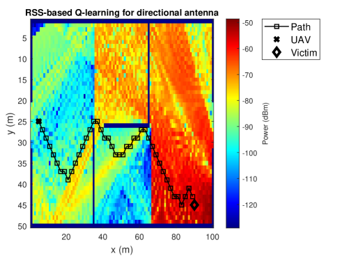
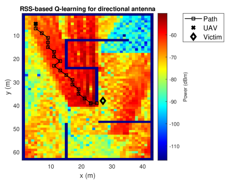
After realization of the proposed algorithm, we implemented the SAR operation for 30000 iterations on different floor plans using a directional antenna. The details of the floor plans used are mentioned in Table I. The results of the algorithm implemented on the floor plans are discussed further. Fig. 5 shows the trajectory followed by the UAV to reach the target which is implemented on floor plan 1. Similarly, it can be seen in Fig. 6 the trajectory followed by UAV on floor plan 2. Both these floor plans have different features and proved to be effective to analyse the performance of the SAR operation.
| Parameter | Value |
|---|---|
| UAV start position | (25 m, 5 m) |
| Target location | (45 m, 90 m) |
| Number of Iterations | 30000 |
| Total time | 74.7 s |
| Trajectory length | 111.34 m |
| Total steps taken | 43 |
| Parameter | Value |
|---|---|
| UAV start position | (5 m, 5 m) |
| Target location | (38 m, 27 m) |
| Number of iterations | 30000 |
| Total time | 20.84 s |
| Trajectory length | 45.11 m |
| Total steps taken | 19 |
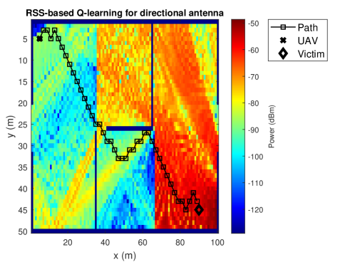
The SAR operation can be determined as successful only when the UAV is able to locate and reach the target. In order to ensure that the UAV completed the SAR operation without collision, we had predefined multiple start positions for the UAV in existing indoor obstacles and obtained the following results.
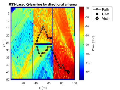
From Fig. 7, if the SAR operation was independent of obstacles, then the UAV would have followed a trajectory having the highest signal power which is a straight path. We have also assumed that the width of the indoor walls is greater than 2 m so that if there is a wall in between the UAV and the victim, the distance between them will always be greater than 2 m. From Fig. 7, we can arrive at the conclusion that even when the UAV had a probable straight path, it followed a different trajectory due to the presence of obstacles. Next, we have compared the elapsed time, total path length and total number of steps taken by UAV for 1000 and 30000 iterations. The number of iterations indicates the degree of freedom given to the UAV to explore the indoor environment. At every iteration, the UAV updates the Q-table and learns more about the environment. The increase in the number of iterations improves the familiarity of the UAV with the environment as well as the probable actions it can take to reach the target.As the number of iterations increase, the UAV takes some time to train itself from its own experiences however it is done at the cost of more accurate results. Table IV and Table V indicate the results obtained on floor plan 1 after altering the number of iterations. As the number of iterations increase, the UAV has more experiences with itself and aids it to reach the target with higher accuracy.

| Parameter | Value |
|---|---|
| UAV start position | (5 m,5 m) |
| Target location | (45 m,90 m) |
| Number of iterations | 1000 |
| Total time | 12.56 s |
| Trajectory length | 111.34 m |
| Total steps taken | 43 |
| Parameter | Value |
|---|---|
| UAV start position | (5 m,5 m) |
| Target location | (45 m,90 m) |
| Number of iterations | 30000 |
| Total time | 45.10 s |
| Trajectory length | 111.34 m |
| Total steps taken | 43 |
It can be observed that the trajectory followed by the UAV remains the same. As the number of iterations increase, the time elapsed also increases. However, this is done at the cost of precise and accurate results.
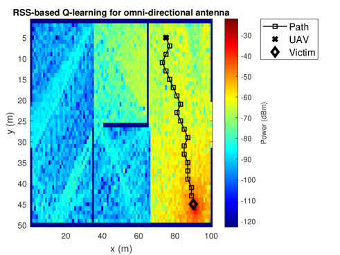
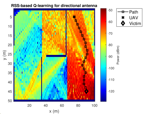
The other parameter which we have taken into consideration for comparison was antenna type. The results of the SAR operation using a directional antenna were compared to that of an omnidirectional antenna. The following are the results obtained on using an omnidirectional antenna for 30000 iterations on floor plan 1.
| Parameters | Directional | Omnidirectional |
|---|---|---|
| UAV start position | (45 m, 90 m) | (45 m, 90 m) |
| Target location | (5 m, 7 m) | (5 m, 7 m) |
| Number of iterations | 30000 | 30000 |
| Total Time | 16.56 s | 17.10 s |
| Trajectory length | 50.43 m | 50.43 m |
| Total steps taken | 20 | 20 |
From Table VI, and Figs. 10-13, it can be inferred that if the UAV’s start location and the victim’s position was static, then the time to converge for a directional antenna is lower than that for the omnidirectional antenna. From this, we can infer that a directional antenna proves to be more efficient for the case of time dependent SAR operation. The realization of an omnidirectional antenna is possible only for simulation purpose while, in real time a directional antenna with low feedback loops, isolation and higher directivity is difficult to design. From Fig. 10 and Fig. 11, we observed that the received signal strength for an omnidirectional and directional antenna is different for the same obstacles and indoor environment. We can thus deduce that a directional antenna is efficient even in environments having weak signals.
We have also compared the performance of the SAR operation in different frequency bands. Radio frequency waves at lower frequencies propagate further than radio frequency waves at higher frequencies. Thus, from Fig. 12 and Fig. 13, we observe that the RSS of 2.4 GHz band is better in comparison to 5 GHz band. Additionally, we can infer that the longer wavelength of 2.4 GHz RF versus 5 GHz RF means that the 2.4 GHz signal will propagate through typical construction walls to a greater degree than the 5 GHz signal [21]. From the results mentioned above, we can broadly infer that as the area of the indoor environment increases, the UAV takes greater time to reach the target. We cannot make this claim concrete as the time taken by the UAV is also dependent on factors like the obstacles in the indoor environment, received signal strength and the net distance between the UAV and the victim.
VII Conclusion
In this paper, we studied a SAR operation by sensing the RSS of the RF signals emitted by the victim’s smart-device in a GPS-denied indoor environment. We considered that the UAV and the victim’s smart device are equipped with directional antennas. We modeled two different indoor scenarios in commercial ray-tracing software and extracted the RSS values which were used to define the states and the rewards for our envisioned Q-learning model. We also carried out simulations for two different frequencies, 2.4 GHz and 5 GHz. Our results show that the change in frequency band resulted in different propagation patterns which affected the convergence time of the UAV. The convergence time required by the directional antenna was turned out to be lesser than that of the omnidirectional antenna. The change in convergence time was due to the concentration of transmitted signals in a specific direction in the case of the directional antenna. Therefore, the use of directional antenna as opposed to an omnidirectional antenna used in [4] proves to be a better choice in weak signal environments.
Probable improvements can be done by considering real-time instances that need SAR operations. One of the possible alterations can be done by allowing the UAV to transmit RF signals in collaboration with a transmitting victim device. This will lead to the generation of RSS at each UAV location dynamically. This will overcome the limitation of the static victim position. Implementation of a multi-agent, multi victim scenario is another modification. The addition of multiple agents and victims in the environment will replicate a real-time scenario adding faster rescue of victims. For implementing this, the interference caused due to the transmission of the RF signals from multiple victims at the same time needs to be considered. Aspects of UAV battery-life, speed, and 3D navigation can also be further explored for more realistic analysis.
References
- [1] M. Mozaffari, W. Saad, M. Bennis, Y. Nam, and M. Debbah, “A tutorial on UAVs for wireless networks: Applications, challenges, and open problems,” IEEE Commun. Surveys Tuts., vol. 21, no. 3, pp. 2334–2360, thirdquarter 2019.
- [2] H. X. Pham, H. M. La, D. Feil-Seifer, and L. Van Nguyen, “Reinforcement learning for autonomous UAV navigation using function approximation,” in Proc. IEEE Int. Symp. Safety Secur. Rescue Rob. (SSRR), Aug. 2018, pp. 1–6.
- [3] M. M. U. Chowdhury, E. Bulut, and I. Guvenc, “Trajectory optimization in UAV-assisted cellular networks under mission duration constraint,” in Proc. IEEE Radio Wireless Symp. (RWS), Jan. 2019, pp. 1–4.
- [4] M. M. U. Chowdhury, F. Erden, and I. Guvenc, “RSS-based Q-Learning for indoor UAV navigation,” in Proc. IEEE Military Commun. Conf. (MILCOM), Norfolk, VA, Nov. 2019, pp. 1–6.
- [5] M. Ezuma, F. Erden, C. K. Anjinappa, O. Ozdemir, and I. Guvenc, “Detection and classification of UAVs using RF fingerprints in the presence of Wi-Fi and Bluetooth interference,” IEEE Open J. Commun. Soc., vol. 1, pp. 60–76, Dec. 2019.
- [6] Statista, “Drones: global market size outlook by application 2020,” https://www.statista.com/statistics/431717/global-uav-market-size-by-application.
- [7] V. Becerra, “Autonomous Control of Unmanned Aerial Vehicles,” https://www.mdpi.com/books/pdfview/book/1377.
- [8] V. M. Becerra, “Autonomous control of unmanned aerial vehicles,” Electronics, vol. 8, no. 4, 2019.
- [9] R. S. Sutton and A. G. Barto, Reinforcement Learning: An Introduction, 2nd ed. The MIT Press, 2018. [Online]. Available: http://incompleteideas.net/book/the-book-2nd.html
- [10] D. P. Bertsekas, Dynamic Programming and Optimal Control, 3rd ed. Belmont, MA, USA: Athena Scientific, 2005, vol. I.
- [11] H. Bayerlein, P. D. Kerret, and D. Gesbert, “Trajectory optimization for autonomous flying base station via reinforcement learning,” in Proc. IEEE Int. Workshop Signal Process. Advances in Wireless Commun. (SPAWC), Kalamata, Greece, June 2018, pp. 1–5.
- [12] N. Imanberdiyev, C. Fu, E. Kayacan, and I. Chen, “Autonomous navigation of UAV by using real-time model-based reinforcement learning,” in Proc. Int. Conf. Control Autom. Robot Vision (ICARCV), Phuket, Thailand, Nov. 2016, pp. 1–6.
- [13] C. Sampedro, A. Rodriguez-Ramos, H. Bavle, A. Carrio, P. de la Puente, and P. Campoy, “A fully-autonomous aerial robot for search and rescue applications in indoor environments using learning-based techniques,” J. Intell. Rob. Syst., vol. 95, no. 2, pp. 601–627, Aug. 2019. [Online]. Available: https://doi.org/10.1007/s10846-018-0898-1
- [14] D. Gandhi, L. Pinto, and A. Gupta, “Learning to fly by crashing,” in Proc. IEEE/RSJ Int. Conf. Intell. Robots Syst. (IROS), 2017, pp. 3948–3955.
- [15] E. Lygouras, N. Santavas, A. Taitzoglou, K. Tarchanidis, A. Mitropoulos, and A. Gasteratos, “Unsupervised human detection with an embedded vision system on a fully autonomous UAVi for search and rescue operations,” Sensors, vol. 19, no. 16, p. 3542, Aug. 2019.
- [16] C. Pu and X. Zhou, “RescueMe: Smartphone-based self rescue system for disaster rescue,” in Proc. IEEE Ann. Comput. Commun. Workshop Conf. (CCWC), Las Vegas, NV, Jan. 2019, pp. 832–837.
- [17] W. Wang, R. Joshi, A. Kulkarni, W. K. Leong, and B. Leong, “Feasibility study of mobile phone WiFi detection in aerial search and rescue operations,” in Proc. Asia-Pacific Workshop Syst., ser. APSys ’13. New York, NY, USA: ACM, 2013, pp. 7:1–7:6.
- [18] C. A. Balanis, Antenna theory: analysis and design. Wiley-Interscience, 2005.
- [19] Remcom: Electromagnetic Simulation Software & EM Modeling. [Online]. Available: https://www.remcom.com/examples/
- [20] A. Al-Hourani, S. Kandeepan, and A. Jamalipour, “Modeling air-to-ground path loss for low altitude platforms in urban environments,” in Proc. IEEE Global Conf. Signal Inf. Process. (GlobalSIP), Austin, TX, Dec. 2014, pp. 2898–2904.
- [21] Laird website, “3 factors that limit range in RF applications,” Laird Wireless Connectivity Blog. [Online]. Available: http://www.summitdata.com/blog/3-factors-limit-range-rf-applications/