Doubly resonant second-harmonic generation of a vortex beam from a bound state in the continuum
Abstract
Second harmonic generation in nonlinear materials can be greatly enhanced by realizing doubly-resonant cavities with high quality factors. However, fulfilling such doubly resonant condition in photonic crystal (PhC) cavities is a long-standing challenge, because of the difficulty in engineering photonic bandgaps around both frequencies. Here, by implementing a second-harmonic bound state in the continuum (BIC) and confining it with a heterostructure design, we show the first doubly-resonant PhC slab cavity with W-1 conversion efficiency under continuous wave excitation. We also report the confirmation of highly normal-direction concentrated far-field emission pattern with radial polarization at the second harmonic frequency. These results represent a solid verification of previous theoretical predictions and a cornerstone achievement, not only for nonlinear frequency conversion but also for vortex beam generation and prospective nonclassical sources of radiation.
I Introduction
The interaction of electromagnetic radiation with an optical medium may lead to a multitude of nonlinear processes due to the intrinsic material susceptibilities, such as the tensor. The latter is responsible, e.g., for frequency down (spontaneous parametric down conversion, SPDC) or up (second-harmonic generation, SHG) conversion, among other frequency mixing processes. Enhancing such processes is desirable for a number of applications including nonlinear spectroscopy [1], frequency doubling of infrared laser sources to the visible or near-infrared, biosensing [2, 3], quantum frequency conversion [4, 5, 6], and generation of non-classical radiation [7, 8, 9, 10].
In SHG and SPDC, in particular, the conversion efficiency can be strongly enhanced in doubly resonant cavities, i.e., simultaneously supporting resonant modes at either first- (FH) or second-harmonic (SH) frequencies, respectively [11, 12, 13, 14]. In such cavities, nonlinear processes are enhanced by the quality () factors of the two modes (i.e., increased temporal confinement), as well as by the spatial field confinement. The latter condition additionally requires that a large spatial overlap between the two fields is fulfilled, which generalizes the phase matching condition in propagating geometries [15]. Doubly-resonant cavities have been proposed and experimentally demonstrated in dual period Bragg mirrors [16, 17, 18], birefringently phase-matched waveguides [19], and geometric dispersion-tuned micro-ring resonators [20, 21]. Photonic crystal (PhC) defect cavities patterned in two-dimensional (2D) slabs, which allow for very tight field confinement in purely dielectric resonators, have been shown to produce significant SHG enhancement in a singly-resonant regime at FH [22, 23, 24, 25, 26, 27, 28, 29, 30]. However, implementing a doubly-resonant condition in PhC slab cavities is a longstanding challenge, because the SH frequency range generally lies entirely inside the light cone of the cladding materials, such that efficient confinement in the out-of-plane direction is prevented, not to mention the difficulty of engineering photonic bandgaps around both frequencies to favor the in-plane confinement.
Recently, a theoretical design strategy based on engineering a bound state in the continuum (BIC) and then employing heterostructure photonic confinement opened up a new path for doubly-resonant cavities on PhC slabs [31]. The BIC is a resonance of an infinitely in-plane extended PhC that lies inside the light cone but is nevertheless non-radiative, either because of symmetry protection or because of destructive interference between different radiation channels [32, 33, 34]. In addition, the in-plane light confinement at SH frequency is ensured by a heterostructure design, which provides a confined mode even in the absence of a photonic bandgap [35]. While the in-plane confinement introduces losses into the light cone for the BIC, this SH confined mode still keeps a reasonably high Q-factor [31]. The confinement at FH frequency is the same as in a conventional PhC approach, i.e. exploiting total internal reflection in the out-of-plane direction and photonic bandgap confinement in the slab plane [28].
The BIC effect in the heterostructure cavity is highly interesting beyond simply being a means to achieve a long-lived mode at SH. In fact, BICs in PhC slabs are associated with a topological charge and are robust to structural modifications [34]. Strikingly, this topological charge manifests itself in the far-field radiation in the vicinity of a BIC in momentum space. Specifically, it was shown that the far-field must be linearly polarized and that, since the emission goes to zero at the BIC, the polarization angle must have a nontrivial winding around it [34]. This has also been demonstrated experimentally [36]. In Ref. [34] it was also proposed that this effect could be used to create vortex beam lasing [37], which can find applications in, e.g., optical trapping [38], light focusing and imaging [37, 39], and communications [40].
Here we make use of such doubly-resonant PhC cavity design strategy and experimentally demonstrate highly efficient SHG in a small-footprint device fabricated in epitaxially grown highly nonlinear wide bandgap GaN material. We also confirm that the SHG signal is a radially polarized vortex beam, a consequence of the BIC, and is highly concentrated around the normal direction. This allows for an extremely high collection efficiency even with a small numerical aperture of the collecting lens, which is different from previous SHG realizations in singly-resonant PhC cavities [23, 24, 26, 28].
II Experiment
II.1 Cavity design
The basic structure of the cavity is a 2D PhC made from a hexagonal lattice of air holes in a slab, where the lattice constant is , the air hole radius is , the slab thickness is and the refractive index is (Fig. 1 a) [31]. A heterostructure design is introduced to the PhC slab by increasing the hole radii (, , ) in three concentric hexagonal regions (core, transition and outer) whose sizes are defined by the side-lengths in units of lattice constant (, , ) (Fig. 1 b). Theoretical simulations have been performed by three-dimensional finite-difference time domain (3D-FDTD). At FH frequency, the in-plane light confinement is ensured by the photonic band bap of the outer region (Fig. 1 d-e), while at SH frequency, the confinement is given by the heterostructure design without a photonic bandgap (Fig. 1 f). Far-field emission pattern at FH frequency is engineered with band-folding, which slightly increases the hole radii, with lattice period , by and in the core and transition regions, respectively. This technique folds the k-vector components at the Brillouin zone edge to the -point in the reciprocal space, which concentrates the emission to the normal direction of the PhC slab and thus increases the in-coupling efficiency at FH frequency [41, 42]. The holes with increased radii are referred to as injectors (or extractors) and their radii are and , respectively.
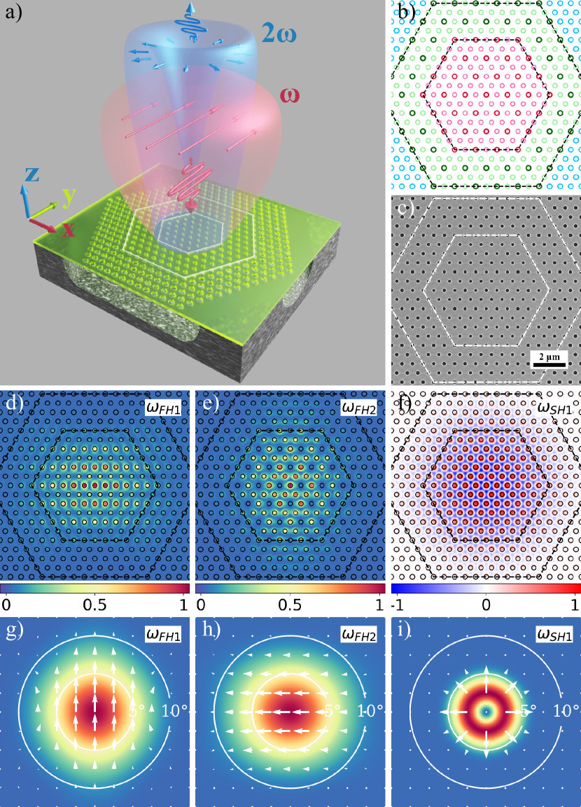
The resonant modes at FH and SH were designed at wavelengths around 1550 nm and 775 nm, respectively, for which the design parameters are: nm, , , , nm, nm, nm, nm, nm, nm (Fig. 1 b). To account for material dispersion, in simulations we assume refractive indices at FH and at SH, respectively. The FH mode is predominantly TE-polarized while the SH mode is predominantly TM-polarized (with respect to the slab plane), and the two are coupled through the and components of the GaN second-order susceptibility tensor. And since the dependencies of FH and SH resonant frequencies on the PhC parameters, such as the lattice constant , the hole radius and the slab thickness , are different, lithographic tuning of these parameters will help to achieve the doubly-resonant condition [31]. In practice, the lattice constant , the hole radii and the slab thickness are scanned around the target values to verify the predicted dependencies, and also to compensate for fabrication imperfections and uncertainty of the refractive index in the experiment compared with the values used in the simulation.
II.2 Fabrication
GaN was chosen to be the slab material because of the perfect combination of a large nonlinear susceptibility and a wide bandgap that accommodates the optical transmission for both pumping wavelengths at the telecom band and SHG wavelength at visible. The fabrication process is similar to that in previous works [43, 28]. The GaN film (around 200 nm) was grown hetero-epitaxially on Si(111) substrate along the c-axis (z-direction) by Metal-Organic Chemical Vapor Deposition (MOCVD) at typically . The Si(111) substrate is placed such that one of the cleavage planes is along the y-direction. An Aluminum Nitride (AlN) buffer layer (around 40 nm) was grown prior to GaN with the same condition to mitigate the lattice mismatch.
The PhC was fabricated through a 2-step ZEP-SiO2 electron beam lithography (Fig. 1 c). First, a layer of 100 nm SiO2 was grown on the GaN surface by Plasma Enhanced Chemical Vapor Deposition (PECVD). Then a layer of around 50 nm positive resist (ZEP520A) was spin-coated on top of SiO2 and was patterned by electron beam (Vistec EBPG5000+). After development, the pattern in the resist was transferred to SiO2 layer to form a hard mask by Inductively Coupled Plasma Reactive Ion Etching (ICP-RIE). After removal of ZEP residue (by remover-1165), another step of ICP-RIE dedicated to III-nitride was applied to transfer the pattern from SiO2 hard mask to GaN/AlN layer. Finally, after removal of residual SiO2 by Hydrogen Fluoride (HF), isotropic Xenon Difluoride (XeF2) gas etching was applied to under-etch the Si substrate through holes in the GaN/AlN layer and an air gap around was created.
II.3 Characterization
II.3.1 Resonances and detuning
Resonant scattering (RS) technique [44] was employed to characterize the cavity resonances at both FH and SH wavelengths. At FH range (around 1550 nm wavelength), the cavity was excited by a linearly polarized beam at normal incidence with E-field at 45 from the x-axis of the cavity, knowing from simulations [31] that the resonant modes are linearly polarized along x or y axis (Fig. 1 g-h). Typically 5 peaks are visible within 5 nm range (Fig. 2 a). The peaks from long wavelength to short are indexed as FH1, FH2 and so on. Q-factor of can be measured for FH1, which is comparable with those measured in GaN-based L3 and H0 singly resonant cavities [28]. The theoretical quality factor of the cavity without the extractors is , while the value with nm is . This suggests that the measured quality factor is limited by the extractor size. Smaller extractors could thus lead to higher and conversion efficiency, since even the nominal cavity without extractors was found to have sizable far field components in the vertical direction [31].
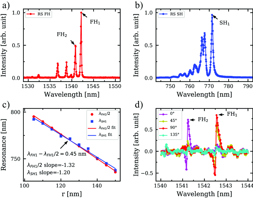
At SH range (around 775 nm wavelength), the mode was excited with the same configuration as for FH. The quasi-TM mode at SH could be excited because of non-zero overlap with the incident E-field (Fig. 1 i). A sharp and intense peak can be observed, together with some higher order peaks at smaller wavelengths (Fig. 2 b). Q-factor of around 800 can be measured while the theoretical value is around 2000. Three-dimensional FDTD simulations suggest that the SH mode Q-factor is not sensitive to the extractor size.
An important characteristic of doubly-resonant cavities is how the two resonances match simultaneously the FH and SH wavelengths. The detuning of doubly resonance can be defined as:
| (1) |
where and are the resonant wavelengths at FH and SH, respectively. The SHG conversion efficiency follows [16]:
| (2) |
where is the excitation wavelength, is the Q-factor of FH resonance, is the Q-factor of SH resonance, is the Lorentzian function of FH resonance, is the Lorentzian function of SH resonance. When exciting the cavity at FH resonance, i.e., , the detuning determines the conversion efficiency via , and the smaller the detuning, the higher the conversion efficiency.
As mentioned before, the PhC parameters, such as lattice constant , hole radius and slab thickness , are lithographically scanned to match the doubly-resonant condition. The dependencies of on PhC hole radius is observed to be more sensitive than that of , and a crossing at around the target hole radius shows up at around the target wavelength, which is in agreement with theoretical predictions [31] (Fig. 2 c). Similar crossings on lattice constant and slab thickness are also achieved (see supplement 1).
II.3.2 FH Cavity mode polarization
The polarization of the first two modes was investigated by exciting the cavity with incident beams at different polarization (Fig. 2 d). The experimental setup was modified from the resonant scattering one [44] such that the polarization of the incident beam could be rotated with a waveplate and the analyzer was removed. The results show that the peak FH1 is excited at around 90 (from x-axis of the cavity) polarization while the peak FH2 at around 0, in agreement with the theoretical predictions (Fig. 1 g-h).
II.3.3 Second harmonic generation
The second harmonic generation was investigated by exciting the cavity with a linearly polarized laser beam, at normal incidence and with the electric field at 45 with respect to the x-axis of the cavity. The collimated beam from a tunable continuous-wave laser source was focused on the cavity by a microscope objective (20, NA=0.4) and the coupling to cavity was optimized by fine translation of the sample in x, y and z directions using a piezoelectric stage. The SHG signal was collected through the same objective, redirected by a dichroic mirror, and detected with a Si photodetector in free space.
| (nm) | () | () | (%) | (mW) | (nW) | (W-1) | ||
| 1 | 0.9 | 1.49 | 804 | 0.2 | 19.6 | 0.541 | 1.120 | 3.810-3 |
| 2 | 0.3 | 1.95 | 724 | 0.8 | 6.9 | 0.125 | 0.372 | 2.410-2 |
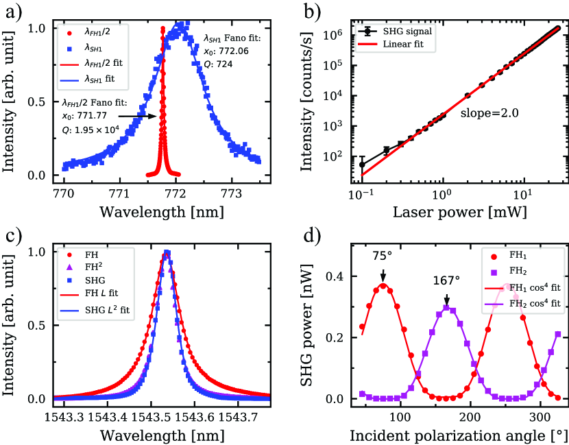
Two cavities are shown as examples (Table 1): one with large detuning (0.9 nm) and the other with small detuning (0.3 nm) (Fig. 3 a) (see supplement 1 for the calibration of conversion efficiency). The ratio of the two conversion efficiencies is very close to the value predicted by Equation 2. Moreover, the record conversion efficiency in the cavity with small detuning, W-1, is 10 times larger than that of singly resonant L3 and H0 cavities [28] ( W-1, ), even with smaller Q-factor at FH, which confirms the great potential of this doubly-resonant PhC cavity scheme for efficient nonlinear frequency conversion.
The SHG process is ascertained by power dependent measurement: by fixing the excitation wavelength at FH1, the SHG intensity scaled quadratically with the excitation power (Fig. 3 b). Alternatively, by fixing the excitation power and scanning the pumping wavelength, the SHG intensity exhibited Lorentzian-squared dependence and matched perfectly with the square of FH resonant scattering intensity, which also confirmed the quadratic nature of the SHG process (Fig. 3 c).
Fine polarization scan shows that the SHG intensity is proportional to , where is the incident polarization angle, and the curve for FH2 is dephased from FH1 by about 90 (Fig. 3 d). Together with the previous resonant scattering experiment, this confirms that the polarization of mode FH1 is around 90 (along with y axis of the cavity) while the polarization of mode FH2 is around 0 (along with x axis of the cavity). The 180 period of both modes and dependence are consistent with the assumption of linear polarization of cavity modes at FH.
II.3.4 SH Far-field emission pattern
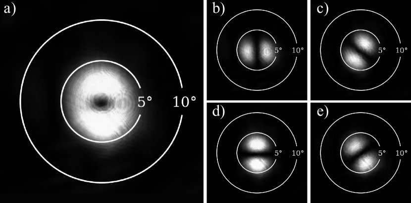
Theoretical analysis and 3D-FDTD simulation predict that the far-field emission at SH frequency is a linearly polarized vector beam with a donut-shaped intensity pattern and radial polarization (Fig. 1 i). This is consistent with the topological nature of BICs in momentum space [34]. To verify this, the SHG far-field emission pattern was investigated by Fourier imaging. After passing through the microscope objective and being redirected by a dichroic mirror, the SHG beam was focused by a lens to form an image of the back focal plane of the objective on a CCD array, and a donut-shaped pattern was directly captured (Fig. 4 a). The donut-shaped far-field pattern is concentrated within a 5 angle, which is in perfect agreement with the simulation.
Moreover, when placing a polarizer film in front of the CCD array, a pattern of two lobes always remains, and its axis, which crosses the centers of the lobes, is always aligned with the polarizer, which confirms the radially polarized nature of the beam (Fig. 4 b-e).
III Discussion
The 3D-FDTD simulation predicts two degenerate modes at FH wavelength with linear polarization of the far-field emission along the x- and y-axis, respectively [31], while the resonant scattering experiment and the fine polarization rotation in SHG experiment show two separated peaks with orthogonal polarization. This suggests that the two orthogonal modes are split in wavelength because of symmetry breaking, commonly observed in optical microcavities affected by disorder [45]. Further 3D-FDTD simulations show that material birefringence and geometrical symmetry breaking (e.g., elliptical holes) can split the degeneracy of the FH mode.
The BIC resonant mode at SH produces a linearly polarized vortex beam with radially winding polarization, which confirms the topological charge description [34]. The donut-shaped far-field emission pattern is highly concentrated around the normal direction, which makes the out-coupling very efficient. Simulations suggest that the symmetry of the far-field emission pattern could be broken by material birefringence and geometry deformation. In practice, the small anisotropy with a higher intensity of the far-field emission pattern in y direction suggests systematic symmetry breaking both at material and geometrical levels, which is consistent with the split peaks at FH.
Although the optimization of material quality and Q-factors were not the main targets during the fabrication process, the Q-factors are comparable with the predicted values, and the SHG conversion efficiencies are significantly higher than that in singly-resonant cavities made of comparable materials and through similar fabrication processes. This shows the robustness of the present design and suggests great potential for improvement in the Q-factors and conversion efficiency. Alternative doubly-resonant cavity designs have been proposed, based on topology optimization of micropost and microrings [15, 46]. However, these designs contain very fine structural features that make them less robust to fabrication imperfections in practice. Further design based on cylindrical dielectric structures has also been demonstrated [47], characterized by a high degree of compactness and sustain quite high excitation powers. However, the measured Q-factors and conversion efficiencies are much lower than the ones shown in the present work, and the BIC mode is in an FH range that requires a vortex beam for efficient pumping, which is less convenient than pumping with linearly polarized beams as in the present case.
IV Conclusion
We have experimentally demonstrated the first doubly-resonant PhC slab cavity, whose Q-factors at FH (around 1550 nm) and SH (around 775 nm) are around and 800, respectively. An experimental SHG conversion efficiency of W-1 is achieved, which is 10 times larger than the previously shown result for a singly-resonant cavity with similar material (i.e., GaN by MOCVD on Si) and processing technique. We also confirmed that the SHG emission pattern is tightly concentrated (5) around the normal direction with donut shape and radial polarization, which originate from the BIC mode at SH.
In this work, the implementation of BIC and heterostructure cavity put forward a practical realization to the long-standing challenge of designing PhC slab cavities fulfilling the doubly-resonant conditions. We notice that significant room for improvement is left for further developments, both at the level of nonlinear overlap factor design and experimental Q-factors, and thus SHG conversion efficiency could ultimately be increased by orders of magnitude in the future. Specific features such as tight light confinement, controllable wavelength detuning, and highly normal direction concentration of both FH and SH beams make this design an ideal platform for on-chip nonlinear light manipulation. In addition, the BIC confinement mechanism provides a natural way to generate a radially polarized vortex beam through the SHG process.
V Acknowledgments
JW and RH would like to acknowledge financial support from the Swiss National Science Foundation, through projects number 2000020-169560 and 200020-188649. DG, AB, MC, MG ackowledge the Horizon 2020 Framework Programme (H2020) through the QuantERA ERA-NET Cofund in Quantum Technologies, project CUSPIDOR, confunded from Ministero dell’Istruzione, dell’Università e della Ricerca (MIUR), and MIUR through the “Dipartimenti di Eccellenza Program (2018-2022)”, Department of Physics, University of Pavia. MM and SF acknowledge the support of a U. S. Air Force Office of Scientific Research MURI project (Grant No. FA9550-17-1-0002).
References
- Heinz et al. [1982] T. F. Heinz, C. K. Chen, D. Ricard, and Y. R. Shen, Spectroscopy of molecular monolayers by resonant second-harmonic generation, Phys. Rev. Lett. 48, 478 (1982).
- Campagnola and Loew [2003] P. J. Campagnola and L. M. Loew, Second-harmonic imaging microscopy for visualizing biomolecular arrays in cells, tissues and organisms, Nat. Biotechnol. 21, 1356 (2003).
- Estephan et al. [2010] E. Estephan, D. Bajoni, M.-b. Saab, T. Cloitre, R. Aulombard, C. Larroque, L. C. Andreani, M. Liscidini, A. M. Malvezzi, and C. Gergely, Sensing by means of nonlinear optics with functionalized GaAs/AlGaAs photonic crystals, Langmuir 26, 10373 (2010).
- Tanzilli et al. [2005] S. Tanzilli, W. Tittel, M. Halder, O. Alibart, P. Baldi, N. Gisin, and H. Zbinden, A photonic quantum information interface, Nature 437, 116 (2005).
- Rakher et al. [2010] M. T. Rakher, L. Ma, O. Slattery, X. Tang, and K. Srinivasan, Quantum transduction of telecommunications-band single photons from a quantum dot by frequency upconversion, Nature Photonics 4, 786 (2010).
- Zaske et al. [2012] S. Zaske, A. Lenhard, C. A. Keßler, J. Kettler, C. Hepp, C. Arend, R. Albrecht, W.-M. Schulz, M. Jetter, P. Michler, and C. Becher, Visible-to-telecom quantum frequency conversion of light from a single quantum emitter, Phys. Rev. Lett. 109, 147404 (2012).
- Majumdar and Gerace [2013] A. Majumdar and D. Gerace, Single-photon blockade in doubly resonant nanocavities with second-order nonlinearity, Phys. Rev. B 87, 235319 (2013).
- Gerace and Savona [2014] D. Gerace and V. Savona, Unconventional photon blockade in doubly resonant microcavities with second-order nonlinearity, Physical Review A 89, 031803 (2014).
- Caspani et al. [2017] L. Caspani, C. Xiong, B. J. Eggleton, D. Bajoni, M. Liscidini, M. Galli, R. Morandotti, and D. J. Moss, Integrated sources of photon quantum states based on nonlinear optics, Light: Science & Applications 6, e17100 (2017).
- Marino et al. [2019] G. Marino, A. S. Solntsev, L. Xu, V. F. Gili, L. Carletti, A. N. Poddubny, M. Rahmani, D. A. Smirnova, H. Chen, A. Lemaître, G. Zhang, A. V. Zayats, C. D. Angelis, G. Leo, A. A. Sukhorukov, and D. N. Neshev, Spontaneous photon-pair generation from a dielectric nanoantenna, Optica 6, 1416 (2019).
- Drummond et al. [1980] P. Drummond, K. McNeil, and D. Walls, Non-equilibrium transitions in sub/second harmonic generation, Optica Acta: International Journal of Optics 27, 321 (1980).
- Paschotta et al. [1994] R. Paschotta, K. Fiedler, P. Kürz, and J. Mlynek, Nonlinear mode coupling in doubly resonant frequency doublers, Applied Physics B 58, 117 (1994).
- Berger [1997] V. Berger, Second-harmonic generation in monolithic cavities, Journal Optical Society America B 14, 1351 (1997).
- Rodriguez et al. [2007] A. Rodriguez, M. Soljačić, J. D. Joannopoulos, and S. G. Johnson, and harmonic generation at a critical power in inhomogeneous doubly resonant cavities, Optics Express 15, 7303 (2007).
- Lin et al. [2016] Z. Lin, X. Liang, M. Lončar, S. G. Johnson, and A. W. Rodriguez, Cavity-enhanced second-harmonic generation via nonlinear-overlap optimization, Optica 3, 233 (2016).
- Liscidini and Andreani [2006] M. Liscidini and L. C. Andreani, Second-harmonic generation in doubly resonant microcavities with periodic dielectric mirrors, Physical Review E 73, 016613 (2006).
- Rivoire et al. [2011] K. Rivoire, S. Buckley, and J. Vučković, Multiply resonant photonic crystal nanocavities for nonlinear frequency conversion, Opt. Express 19, 22198 (2011).
- Buckley et al. [2014a] S. Buckley, M. Radulaski, J. L. Zhang, J. Petykiewicz, K. Biermann, and J. Vučković, Multimode nanobeam cavities for nonlinear optics: high quality resonances separated by an octave, Opt. Express 22, 26498 (2014a).
- Scaccabarozzi et al. [2006] L. Scaccabarozzi, M. M. Fejer, Y. Huo, S. Fan, X. Yu, and J. S. Harris, Enhanced second-harmonic generation in algaas/alxoy tightly confining waveguides and resonant cavities, Opt. Lett. 31, 3626 (2006).
- Pernice et al. [2012] W. H. P. Pernice, C. Xiong, C. Schuck, and H. X. Tang, Second harmonic generation in phase matched aluminum nitride waveguides and micro-ring resonators, Applied Physics Letters 100, 223501 (2012), https://doi.org/10.1063/1.4722941 .
- Bruch et al. [2018] A. W. Bruch, X. Liu, X. Guo, J. B. Surya, Z. Gong, L. Zhang, J. Wang, J. Yan, and H. X. Tang, second-harmonic conversion efficiency in single-crystalline aluminum nitride microresonators, Applied Physics Letters 113, 131102 (2018).
- McCutcheon et al. [2007] M. W. McCutcheon, J. F. Young, G. W. Rieger, D. Dalacu, S. Frédérick, P. J. Poole, and R. L. Williams, Experimental demonstration of second-order processes in photonic crystal microcavities at submilliwatt excitation powers, Phys. Rev. B 76, 245104 (2007).
- Rivoire et al. [2009] K. Rivoire, Z. Lin, F. Hatami, W. T. Masselink, and J. Vučković, Second harmonic generation in gallium phosphide photonic crystal nanocavities with ultralow continuous wave pump power, Opt. Express 17, 22609 (2009).
- Galli et al. [2010] M. Galli, D. Gerace, K. Welna, T. F. Krauss, L. O’Faolain, G. Guizzetti, and L. C. Andreani, Low-power continuous-wave generation of visible harmonics in silicon photonic crystal nanocavities, Opt. Express 18, 26613 (2010).
- Yamada et al. [2014] S. Yamada, B.-S. Song, S. Jeon, J. Upham, Y. Tanaka, T. Asano, and S. Noda, Second-harmonic generation in a silicon-carbide-based photonic crystal nanocavity, Opt. Lett. 39, 1768 (2014).
- Buckley et al. [2014b] S. Buckley, M. Radulaski, J. Petykiewicz, K. G. Lagoudakis, J.-h. Kang, M. Brongersma, K. Biermann, and J. Vučković, Second-Harmonic Generation in GaAs Photonic Crystal Cavities in (111)B and (001) Crystal Orientations, ACS Photonics 1, 516–523 (2014b).
- Zeng et al. [2015] Y. Zeng, I. Roland, X. Checoury, Z. Han, M. El Kurdi, S. Sauvage, B. Gayral, C. Brimont, T. Guillet, M. Mexis, et al., Resonant second harmonic generation in a gallium nitride two-dimensional photonic crystal on silicon, Appl. Phys. Lett. 106, 081105 (2015).
- Mohamed et al. [2017] M. S. Mohamed, A. Simbula, J.-F. Carlin, M. Minkov, D. Gerace, V. Savona, N. Grandjean, M. Galli, and R. Houdré, Efficient continuous-wave nonlinear frequency conversion in high-Q gallium nitride photonic crystal cavities on silicon, APL Photonics 2, 031301 (2017).
- Song et al. [2019] B.-S. Song, T. Asano, S. Jeon, H. Kim, C. Chen, D. D. Kang, and S. Noda, Ultrahigh-q photonic crystal nanocavities based on 4h silicon carbide, Optica 6, 991 (2019).
- Clementi et al. [2019] M. Clementi, K. Debnath, M. Sotto, A. Barone, A. Z. Khokhar, T. D. Bucio, S. Saito, F. Y. Gardes, D. Bajoni, and M. Galli, Cavity-enhanced harmonic generation in silicon rich nitride photonic crystal microresonators, Appl. Phys. Lett. 114, 131103 (2019).
- Minkov et al. [2019] M. Minkov, D. Gerace, and S. Fan, Doubly resonant nonlinear photonic crystal cavity based on a bound state in the continuum, Optica 6, 1039 (2019).
- Hsu et al. [2016] C. W. Hsu, B. Zhen, A. D. Stone, J. D. Joannopoulos, and M. Soljačić, Bound states in the continuum, Nat. Rev. Mater. 1, 16048 (2016).
- Hsu et al. [2013] C. W. Hsu, B. Zhen, J. Lee, S.-L. Chua, S. G. Johnson, J. D. Joannopoulos, and M. Soljačić, Observation of trapped light within the radiation continuum, Nature 499, 188 (2013).
- Zhen et al. [2014] B. Zhen, C. W. Hsu, L. Lu, A. D. Stone, and M. Soljačić, Topological nature of optical bound states in the continuum, Phys. Rev. Lett. 113, 257401 (2014).
- Ge et al. [2018] X. Ge, M. Minkov, S. Fan, X. Li, and W. Zhou, Low index contrast heterostructure photonic crystal cavities with high quality factors and vertical radiation coupling, Appl. Phys. Lett. 112, 141105 (2018), https://doi.org/10.1063/1.5026433 .
- Doeleman et al. [2018] H. M. Doeleman, F. Monticone, W. Den Hollander, A. Alù, and A. F. Koenderink, Experimental observation of a polarization vortex at an optical bound state in the continuum, Nat. Photonics 12, 397 (2018).
- Zhan [2009] Q. Zhan, Cylindrical vector beams: from mathematical concepts to applications, Adv. Opt. Photon. 1, 1 (2009).
- Ng et al. [2010] J. Ng, Z. Lin, and C. T. Chan, Theory of optical trapping by an optical vortex beam, Physical Review Letters 104, 103601 (2010).
- Kitamura et al. [2012] K. Kitamura, K. Sakai, N. Takayama, M. Nishimoto, and S. Noda, Focusing properties of vector vortex beams emitted by photonic-crystal lasers, Opt. Lett. 37, 2421 (2012).
- Wang [2016] J. Wang, Advances in communications using optical vortices, Photon. Res. 4, B14 (2016).
- Combrié et al. [2009] S. Combrié, A. De Rossi, et al., Directive emission from high-q photonic crystal cavities through band folding, Physical Review B 79, 041101 (2009).
- Portalupi et al. [2010] S. L. Portalupi, M. Galli, C. Reardon, T. Krauss, L. O’Faolain, L. C. Andreani, and D. Gerace, Planar photonic crystal cavities with far-field optimization for high coupling efficiency and quality factor, Opt. Express 18, 16064 (2010).
- Vico Triviño et al. [2013] N. Vico Triviño, U. Dharanipathy, J.-F. Carlin, Z. Diao, R. Houdré, and N. Grandjean, Integrated photonics on silicon with wide bandgap gan semiconductor, Applied Physics Letters 102, 081120 (2013).
- Galli et al. [2009] M. Galli, S. Portalupi, M. Belotti, L. Andreani, L. O’Faolain, and T. Krauss, Light scattering and fano resonances in high-q photonic crystal nanocavities, Applied Physics Letters 94, 071101 (2009).
- Hennessy et al. [2006] K. Hennessy, C. Högerle, E. Hu, A. Badolato, and A. Imamoğlu, Tuning photonic nanocavities by atomic force microscope nano-oxidation, Appl. Phys. Lett. 89, 041118 (2006).
- Lin et al. [2017] Z. Lin, M. Lončar, and A. W. Rodriguez, Topology optimization of multi-track ring resonators and 2d microcavities for nonlinear frequency conversion, Optics Letters 42, 2818 (2017).
- Koshelev et al. [2020] K. Koshelev, S. Kruk, E. Melik-Gaykazyan, J.-H. Choi, A. Bogdanov, H.-G. Park, and Y. Kivshar, Subwavelength dielectric resonators for nonlinear nanophotonics., Science 367, 288 (2020).