Unsupervised Deep Learning for Massive MIMO Hybrid Beamforming
Abstract
Hybrid beamforming is a promising technique to reduce the complexity and cost of massive multiple-input multiple-output (MIMO) systems while providing high data rate. However, the hybrid precoder design is a challenging task requiring channel state information (CSI) feedback and solving a complex optimization problem. This paper proposes a novel RSSI-based unsupervised deep learning method to design the hybrid beamforming in massive MIMO systems. Furthermore, we propose i) a method to design the synchronization signal (SS) in initial access (IA); and ii) a method to design the codebook for the analog precoder. We also evaluate the system performance through a realistic channel model in various scenarios. We show that the proposed method not only greatly increases the spectral efficiency especially in frequency-division duplex (FDD) communication by using partial CSI feedback, but also has near-optimal sum-rate and outperforms other state-of-the-art full-CSI solutions.
Index Terms:
Massive MIMO, Hybrid beamforming, Beam training, Deep learning, Unsupervised learning.I Introduction
New applications such as internet-of-things (IoT) and vehicular communications continuously increase the demands for higher data rate. To face this challenge, massive multiple-input multiple-output (MIMO) has become an essential factor in the design of future cellular systems [1]. In massive MIMO, the number of antennas in the base station (BS) scales up to serve several users and it was shown in [2] that the effects of fast fading and interference vanish when increasing the number of antenna in the BS. Higher multiplexing and diversity gain are thus obtained with massive MIMO, which in turn results in a higher spectral efficiency and greater energy efficiency.
On the other hand, each antenna in a massive MIMO array requires a radio-frequency (RF) chain. Therefore, the power consumed by RF elements such as power amplifiers renders massive MIMO systems expensive and energy inefficient. To address this power consumption issue, reduce the cost-power hardware overhead, and yet provide reasonable performance, the hybrid beamforming (HBF) technique was introduced [3]. It consists of using a small number of analog beamformers deployed to drive multiple antennas to form a beam, each connected through a single RF chain to a digital precoder. This hybrid combination of phase-based analog and baseband digital beamformers reduce the number of transmission chains while keeping the sum-rate to an acceptable level [4, 5]. In fact, hybrid beamforming techniques have been considered for fifth generation cellular network technology (5G) in the millimeter wave (mm-Wave) bands [6]. However, an explicit estimate of the mm-Wave channel is generally needed to design the hybrid beamforming matrices at the transmitter. Although several channel estimation techniques for hybrid beamforming have been proposed in the last few years [7], channel estimation remains a complicated task due to the hybrid structure of the precoding and to the imperfections of the RF chain. Among prior research, the authors in [8] designed hybrid beamforming by considering orthogonal frequency division multiplexing (OFDM)-based frequency-selective structures. The wideband mm-Wave massive MIMO systems was investigated in [9] to design the hybrid beamforming. In [10], the authors designed an analog beamformer based on the second-order spatial channel covariance matrix of a wideband channel. Authors in [11] assumed to have perfect knowledge of the channel state information (CSI) and proposed a low-complexity hybrid beamforming. All of the aforementioned methods strongly depend on full knowledge of the CSI or channel estimation by using pilots, which increases the signaling overhead and, therefore, reduces the spectral and energy efficiency of the system especially in frequency division duplex (FDD) communication where CSI acquisition and feedback is a challenging task [12]. Therefore, in this paper we propose a system that, instead of considering the full knowledge of CSI or channel reciprocity, uses the received signal strength indicators (RSSI) to design the hybrid beamforming precoders. Unlike CSI, RSSI is a single real value which users readily measure from the received signal. By consequence, no explicit CSI feedback is required, which reduces the signaling overhead and increases the spectral efficiency of the system.
Meanwhile, deep learning (DL) techniques have recently been applied widely to telecommunication system [13] and it was demonstrated to be an outstanding tool for dealing with complex non-convex optimization problems, thanks to its excellent classification and regression capabilities. Although the training process can be time consuming, the training is done in “off-line” mode. Therefore, DL techniques are a promising approach to reduce the latency in cellular network. Several works have investigated the use of deep neural network (DNN) to deal with difficult problems within the physical layer [14], including channel coding, channel estimation [15], detection [16] and, beamforming [17, 18, 19, 20, 21]. In particular, the authors of [17] considered a multi-input single-output system and solved three optimization problems. By using DNN with fully-connected layer (FL) and decomposition of the channel matrix in [19], the near-optimal analog and digital precoders have been designed. In [18, 19], the authors propose a deep supervised learning based method to estimate the hybrid beamforming by knowing the full CSI. In [20], a supervised deep learning-based hybrid beamforming design for coordinated beamforming is proposed. The authors in [21] deployed a convolution neural network (CNN) to design the hybrid beamforming, by knowing the CSI. In all the mentioned literature, perfect knowledge of CSI is assumed to be available at the BS, and the DNNs are trained using supervised learning. However, supervised learning requires the optimum targets to be known, and thus requires significant additional computing resources to find these targets using conventional optimization methods. In addition, in practical situations, the knowledge of the optimum hybrid beamforming structure is hard to obtain.
Therefore, we introduce in this work a novel approach with RSSI-based unsupervised learning to design the HBF in massive MIMO system, improved from our first proposal where supervised deep learning was considered [22]. To the best of the authors knowledge, it is the first time that an unsupervised DL system is proposed for designing hybrid beamforming precoders in the context of massive MIMO systems. Furthermore, we train the DNN specifically for the area where the BS is located, so that the geometrical structure of the channel model can be learned. In this paper, this is done using a ray-tracing model [23]. The same approach could also be used to train the DNN using direct measurements of the environment. The proposed DNN architecture is a multi-tasking CNN that generates both the analog and digital parts of the hybrid beamforming, enabling to reduce the computational complexity. Furthermore, a novel loss function based on sum-rate is proposed. To train the model, we introduce methods to generate datasets and codebooks based on the deepMIMO channel model [23]. Particularly, the synchronization signals transmitted by the BS are optimized in such a way that the RSSI measurements carry the maximum information about the CSI. Three different channel models have been examined to validate the reliability and robustness of the proposed method in different scenarios. These three scenarios have been chosen to cover different environments, received signal strengths and cell coverage. Moreover, we study the effect of RSSI quantization on the DNN’s performance. The simulation results show that the sum-rate performance of the proposed RSSI-based model outperforms other state-of-the-art full-CSI methods while the spectral efficiency, signaling overhead, training time and flexibility of the system are significantly improved.
The major contributions of the paper can be summarized as follows:
-
•
a method to design the codebook for the phase-based analog precoder (AP);
-
•
a method to design synchronization burst sequences maximizing the channel information carried by the RSSI;
-
•
a procedures to generate the DNN datasets;
-
•
a low complexity approach for fully digital precoder and hybrid beamforming design; and
-
•
two unsupervised deep learning methods to directly design the hybrid beamforming.
The rest of the paper is organized as follows. Section II describes the system model, including beam training during initial access (IA), RSSI measurement and quantization. In Section III, the channel model and dataset generation for DNN training are presented, followed by the near-optimal HBF solutions for massive MIMO. The proposed method for synchronization signal (SS) planning in IA and codebook design for the analog precoder are described in Section IV. In Section V, the DNN architecture and the unsupervised learning method are presented. Finally, in Section VI the proposed HBF methods are evaluated and compared with existing methods, and conclusions are drawn in Section VII.
Notation: Matrices, vectors and scalar quantities are denoted by boldface uppercase, boldface lowercase and normal letters, respectively. The notations , , , , , , and denote Hermitian transpose, transpose, Moore-Penrose pseudoinverse, absolute value, -norm, matrix inverse, real part, and imaginary part, respectively.
II System Model
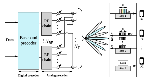
The considered system model consists of a massive MIMO BS in a single-cell system equipped with antennas and RF chains serving single-antenna users, as shown in Fig. 1. For both uplink and downlink transmission, HBF precoders are employed by the BS. We consider a fully connected architecture where each RF chain is coupled through 2-bit phase shifters to all antennas at the BS. A 3-step scenario similar to the one described in [22] is investigated in the following sub-sections.
II-A Step 1: SS Bursts Transmission
In the first step shown on the right side of Fig. 1, the BS transmits SS bursts, where each burst uses different 2-bit phase-shift analog precoders . The SS are received by all users in the cell. By consequence, the received signal at the user for the burst can be written as
| (1) |
where stands for the channel vector from the antennas at the BS to user and is the additive white gaussian noise (AWGN) term.
II-B Step 2: RSSI Feedback
After receiving , the averaged RSSI value are measured by the user for the SS burst, which constitutes the second step. Therefore, we have
| (2) |
where is the noise power. All RSSI values of each user are then transmitted to the BS through a dedicated error-free feedback channel. These two first steps correspond to the establishment of the IA between the BS and the users.
In practical systems, due to the limited precision of the measurements and limitation in feedback channel, the RSSIs must be quantized. Let us denote by the vector of all RSSI values obtained by the user, re-scaled by a factor to ensure that . Then, we define as the quantized RSSI vector of user transmitted to the BS. Several quantization methods can be employed. We use linear quantization, given by
| (3) |
where is the round operator and is the number of quantization bits. We study the effect of quantization on performance in Section VI.
II-C Step 3: Downlink Data Transmission
The last step corresponds to the downlink transmission where the BS transmits data to each user. The digital precoder matrix is where vector is designed to encode the data symbol of user index . The analog precoder is designed to transfer the output of the RF chain to antennas and applies to all users. To reduce the complexity of the HBF design, we consider that the analog precoder is chosen from a codebook composed of a set of analog beam codewords where is the analog precoder matrix of the codebook (the codebook design is discussed in Section IV).
The signal-to-interference-noise ratio (SINR) of the user received signal for a given hybrid beamformer is then expressed as
| (4) |
and the spectral efficiency of the system can be obtained by evaluating the sum-rate expressed as
| (5) |
Then, the HBF design consists of finding the digital precoder vectors and the analog pecoder matrix in the codebook that maximize the sum-rate (5). This problem is however difficult to solve as, in our case, the BS does not have a direct knowledge of the channel coefficients and the noise power . The CSI is in fact partially embedded in the received RSSIs. Therefore, we propose to employ DNN techniques to design the HBF precoders.
III Dataset Generation for DNN
To train the DNNs, a dataset must be obtained beforehand. In practice, this dataset could be generated from channel measurements performed by the BS, while in this paper the channel measurements based on the system model described in Section II must be simulated. This section describes the channel model and dataset generation procedure followed by the near-optimal full-CSI solution for the HBF and fully digital precoder (FDP) techniques. The HBF and FDP described in this section are used as an upper bound to evaluate the unsupervised DNN performance.
III-A Channel Model
The deepMIMO [23] millimeter-wave massive MIMO dataset model is used to generate the channel coefficients for the train and test datasets. In this model, realistic channel information is generated by applying ray-tracing methods to a three-dimensional model of an urban environment. It provides the channel vector (of length ) for each user position on a quantized grid. The considered set of channel parameters from this model are summarized in Table I. Scenario “O1” consists of several users being randomly placed in two streets surrounded by buildings. These two streets are orthogonal and intersect in the middle of the map.
| System | Antennas | ||
|---|---|---|---|
| Parameter | Value | Parameter | Value |
| scenario | “O1” | num_ant_x | |
| bandwidth | GHz | num_ant_y | |
| num_OFDM | num_ant_z | ||
| num_paths | ant_spacing | ||
A channel matrix entry in the dataset is obtained by concatenating channel vectors selected randomly from the available user positions of the considered area.
III-B Dataset Generation Method
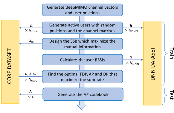
Two datasets are generated for training and testing the network. The first one, referred to as the core dataset, contains channel realizations. This dataset is used to design the codebook and the analog precoder of the SS burst . Furthermore, near-optimal FDP and HBF precoder solutions are computed to compare the sum-rate performance of the DNN. It is worth mentioning that, as described in Section V, the proposed DNN architecture is unsupervised, and does not exploit the near-optimal solutions during training.
The second dataset contains channel realizations and their related RSSIs measured from the burst generated from the core dataset. It is used to train and test the DNN. Note that we have as the core dataset requires resolving computationally heavy optimization problems, and we empirically found that samples is sufficient to obtain good codebook and SS design.
Fig. 2 shows the steps performed to generate both datasets, and the next sections provide more detail about the near-optimal design of the full digital and HBF precoders, the codebook generation and the SS bursts design.
III-C Fully Digital Precoder Design
Several FDP optimization techniques have been proposed in the literature to maximize the sum-rate. Most of these techniques are computationally heavy when applied for massive MIMO cases, but the optimal FDP is needed to evaluate the performance of the DNN. The FDP design problem corresponds to solving the following optimization problem:
| (6a) | |||||
| s. t. | (6b) | ||||
where stands for the maximum transmission power, and
| (7) |
The method we employed to find the optimal FDP is based on [24], where it is demonstrated that the optimal FDP vector of FDP matrix for user has the following analytical structure:
| (8) |
where corresponds to the number of users, corresponds to the identity matrix, and are the unknown real-valued coefficients to be optimized, respectively corresponding to the beamforming power and Lagrange multiplier for the user . In addition, we have and .
Therefore, only real-valued coefficients must be evaluated to resolve the optimization problem, instead of the initial complex coefficients. The particle swarm optimization (PSO) [25] algorithm can then be employed to obtain the optimal coefficients. However, we empirically found that near-optimal solutions can be obtained by assuming that and by evenly distributing the power over users and setting for the remaining users. Therefore, solutions have to be evaluated to find the near-optimal one.
III-D Hybrid Beamforming Design
When considering hybrid beamforming, (4) can be rewritten as
| (9) |
From (9), , , can be seen as a virtual channel matrix with spatial paths. In this virtual system, is the FDP matrix of a transmitter with virtual antennas. Then, if is known, the optimization method presented in III-C can be re-used to find the optimal digital precoder . Therefore, the analog precoder must be designed first. We propose to find such that the channel capacity [26] of is maximized, giving the following integer nonlinear programming problem:
| (10) |
where is the eigenvalue of , and is the waterfill level chosen to satisfy the following equation:
| (11) |
with corresponding to the signal-to-noise ratio (SNR). To solve this problem, we used the genetic algorithm [27]. This iterative algorithm consists, for each iteration (or “generation”), of selecting, mutating and merging solutions from a set of candidate solutions (referred as “population”) who gives the best score with respect to the objective function (the sum-rate in our case). At the first generation, candidates are generated randomly. The process of selection consists of keeping, for the next iteration, the solutions, referred as elites, which maximize the score. The mutation process makes small random changes on the population, excluding the elites. Finally, the merging process, called crossover, generate new solutions by mixing solutions from the previous population, with being the crossover factor. To optimize the analog precoder, we set the genetic algorithm parameters to , and . This hybrid beamforming design will be referred to as the Hybrid Structured Heuristic Optimization (HSHO) method.
It is worth noting that the design of the precoders (step ) has an impact on the amount of channel information carried by the RSSIs (step ), which in turn affects the quality of the HBF solutions obtained by the DNN and the performance of uplink transmission in step . In addition, the codebook design can also greatly affect the performance of the DNN. Therefore, the codebook and SS for initial access need to be carefully planned.
IV Synchronization Signal and Codebook design
In this section, we address the problem of the SS burst and analog beamformer codebook design with novel methods.
IV-A Proposed SS Burst Design
As mentioned in Section II-C, the design of the SS burst can impact the HBF sum-rate performance because it affects the amount of information that is revealed by the RSSI measurements about the CSI. The synchronization signal burst (SSB) length also impacts the system data rate in both downlink and uplink. Therefore, it is important to design the SSB so that the measured RSSIs provide the maximum information about the CSI while minimizing the amount of data to transmit in the feedback channel.
To resolve this problem, we propose to find the SS sequences that maximize the mutual information between the channel matrices and the quantized RSSIs matrix with being the number of SS burst
| (12) |
where is the quantization function defined in (3), and where corresponds to the entropy of the variable and is the joint entropy of the variables , quantized on values, defined as
| (13) |
with denoting probability. Furthermore, we have . It is worth mentioning that there is no need to include more than one user in the calculation of . In fact, user positions are selected randomly and independently, therefore knowing the RSSI of one user cannot provide any information for a second user.
A straightforward computation of (12) can be computationally heavy, particularly when used in an optimization loop and in the case of massive MIMO. To reduce the complexity, we assumed that there exists a bijective function that links the channel matrix and the quantized user positions in the environment. In fact, this assumption is quite realistic due to the high channel diversity induced by massive MIMO systems. Under this assumption, we have . Finally, the genetic algorithm with the same parameters as described in Section III-D is used to design the SS burst sequences , by solving the following optimization problem:
| (14) |
Note that gives the theoretical minimum number of bits required by the feedback channel to transmit all the information about the CSI. Since the user positions are selected randomly with uniform probability on a set of different locations, we also have .
IV-B Proposed Codebook Design
To reduce the complexity of the AP design task for the DNN described in the next section, we propose to restrict the possible AP solutions to a subset (codebook) of solutions (codewords), directly chosen during the optimization phases when generating the core dataset. This is achieved through three successive steps described below.
The first step consists of generating a first codebook when the near-optimal analog and digital precoder solutions presented in Section III-D are iteratively evaluated for each channel realization. Let us respectively denote and the AP and digital precoder (DP) solutions related to the channel matrix of the core dataset. Each of these solutions has sum-rate , which can be calculated from (5). As a reminder, denotes the analog precoder in the codebook. Then, is appended in the codebook if
| (15) |
where is an arbitrary threshold value, set to in our setup, to decide if the analog precoder will be appended to the codebook, and is the DP solution for the channel matrix in the dataset when the analog precoder is chosen. Therefore, each analog precoder solution solved using the genetic algorithm is appended in the codebook if the obtained sum-rate is higher than times the best sum-rate obtained with the APs in the current codebook. Otherwise, the obtained HBF solution is replaced by the one in the codebook having the highest sum-rate. To avoid high computational overhead, no APs are appended to the codebook when its size reaches APs.
Since the APs are iteratively appended in the first step, it may be possible that better AP solutions are found in the later iterations. Therefore, the sum-rate could be improved for the first channel matrices in the dataset. To address this issue, the second step aims to update the AP solutions for each channel matrix in the dataset by choosing the AP in the codebook, obtained in the first step, that maximize the sum-rate:
| (16) |
The final step consists of reducing the size of the codebook while keeping an acceptable level of average sum-rate over the whole dataset. We denote the set of AP index in the core dataset that use the AP label number () in the current codebook as solution. To reduce the codebook size , where represent the cardinality operator in this context, the following operations are iteratively executed:
-
•
The codebook is sorted in ascending order such that ,
-
•
All the APs in the core dataset using the AP codeword (indexed in ) are moved to other AP codewords giving the best sum-rate:
(17) -
•
The AP codeword is then removed from the codebook.
Each time a codeword is removed, the average sum-rate over the core dataset is reduced. To maintain good performance, the codebook size reduction is stopped when the average sum-rate reaches % of the initial sum-rate.
V RSSI-Based Hybrid Beamforming with Deep Neural Network
In this section, we propose a novel RSSI-based method to design the HBF for massive MIMO systems. The RSSI measurements by the users was explained in Section II-B. The BS receives the quantized RSSI, through a dedicated error-free feedback channel. Then, the BS designs the HBF matrices used to transmit data to users in the downlink step, as described in Section II-C. In supervised learning, a computationally heavy optimization problem must be solved not only for each sample in the dataset, but also for each BS in the cellular network because the dataset generation depends on the location of the BS. On the contrary, in unsupervised learning, the BS can be trained directly using data measured from the environment, thus significantly reducing the computational complexity of the training in the network.
V-A Deep Neural Network Architecture
Two approaches are considered to obtain the HBF solution. In the first approach, we design a DNN, called “HBF-Net”, to jointly predict the analog precoder and digital precoder . In the second approach, referred to as “AFP-Net”, the DNN predicts the analog and fully digital precoders . The digital precoder is then computed using
| (18) |
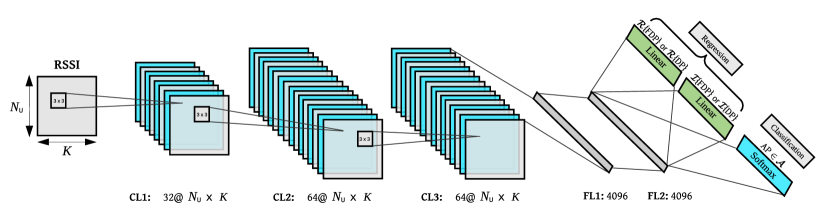
The AFP-Net approach ensures that the alignment between analog and digital precoders is maintained. In both approaches, the DNN architecture is composed of a classification task for the analog precoder prediction, and of a regression task for the digital precoder prediction. To reduce the number of parameters and accordingly the computational complexity, we design a multi-tasking DNN [28] to perform both tasks in a single DNN. The proposed DNN architecture is shown in Fig. 3. Referring to Fig. 3, the input of the DL model is the quantized RSSIs received at the BS followed by shared convolutional layer (CL), FL layers and an output layer for each task. It is worth noting that for both HBF-Net and AFP-Net, the DNN has the same architecture, except for the dimension of the output layer. Since we separate the real and imaginary parts of the output, the dimension of the output layer for DP task in HBF-Net is , and for FDP task in AFP-Net. The dimension of the AP task is the same for both approaches and it is equal to size of the codebook (). The CLs use the “Same” convolution operators where the dimension of the inputs and outputs are preserved. After each layer, we use batch normalization to reduce the internal covariate shift and accelerate the learning. In fact, batch normalization is a kind of regularization technique which prevents over-fitting because of its noise injection effect [29]. Since we have used batch normalization technique, the dropout probability for all layers is selected to a very small value () to avoid the over regularization problem. The dropout layers reduce the impact of the choice of initial weights [30]. In addition, we use the leaky ReLU activation function in each layer (except the output layers), to fix the dying ReLU problem after batch normalization [31]. This activation function with input and output is given by
| (19) |
This function does not have a zero-slope part [31]. For the output layer of the classifier or AP task, we use a conventional “Softmax” activation function defined as
| (20) |
where is the value of the output of the DNN in AP task part and is the corresponding output of the Softmax activation function. Thus, the output vector of the classifier after activation function is where from Section IV-B we consider that . Finally, we used the “Adam” algorithm as network optimizer and “ReduceLROnPlateau” to schedule the reduction of learning rate [32].
As shown in Fig. 3, the output of the FDP task is separated into real and imaginary parts. Some DL framework only support real algebra, and therefore cannot directly support complex-valued computation. Therefore, we separately deploy the real and imaginary part to compute the loss function. Then, to compute the pseudoinverse of all codewords , we use . To compute the , we define the square matrix and where and are purely real. We then have the following relations based on [33]:
| (21) |
Eq. (V-A) is valid when the matrix is non-singular, which holds in our case. In other cases where is singular, the corresponding equations are listed in [33]. To obtain the predicted digital precoders in (18), we compute
| (22) |
and then, is formed.
V-B Unsupervised Training
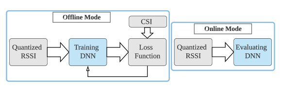
We propose a novel loss function to train both AP task and DP or FDP tasks without any target. Further, as shown in Fig. 4, the full CSI is only used in training mode to calculate the unsupervised loss function, and in evaluation mode, only the RSSI information is used at the BS and the BS does not have access to CSI.
Since we design the hybrid beamforming with two different approaches, each approach requires its own loss function for training. As a reminder, the sum-rate achieved by the HBF is given by (5), and based on (20), we define as the output vector of the AP task. We define below the unsupervised loss function for each approach.
V-B1 HBF-Net
The DNN in this approach is trained to jointly design the DP and AP directly from RSSIs. For this approach we define the unsupervised loss function as
| (23) |
where is the analog precoder of the codebook and is the output of the DP task. To satisfy we further normalize . The negative sign allows the sum-rate to be maximized when the DNN is trained to minimize the loss function. Algorithm 1 summarizes the steps to train the HBF-Net.
V-B2 AFP-Net
The loss function in this approach is different because here we aim to design the digital precoder from the FDP and AP. To do so, we first obtain the FDP and AP, and then by using (18), DP can be computed. If we define
| (24) |
the loss function for the FDP task can be defined as
| (25) |
where is the output of FDP task in AFP-Net. This loss function results in the maximization of the FDP sum-rate. Here again, we normalize to satisfying . Now, by knowing the FDP, given AP, we compute , where is the DP matrix obtained from (18) for the codeword in the codebook. The loss function for the AP task is defined as
| (26) |
where unlike (23), this loss function is only tuning the Softmax outputs of the AP task. The final loss function for AFP-Net is defined as
| (27) |
so that the DNN maximizes the FDP sum-rate while also maximizing the HBF sum-rate by selecting the appropriate AP from the codebook. Algorithm 2 summarizes the steps to train the AFP-Net.
It can be seen that AFP-Net is more complex than HBF-Net, which directly outputs the hybrid beamforming solution. However, as shown in Section VI, AFP-Net achieves better sum-rate performance by keeping the alignment between the analog and digital precoder.
V-C Evaluation Phase
In the evaluation phase, a part of the DNN dataset is dedicated to test the network, as presented in Section III-B. We used the sum-rate metric to characterize the performance. For the evaluation phase, the maximum value of the “Softmax” output is selected in the classifier. So, we can compute the sum-rate of HBF to evaluate its performance using , where is the analog precoder predicted by the AP task, expressed as where , and is the predicted digital precoder of HBF-Net or AFP-Net obtained from (18). To satisfy the power constraint we normalize the to have .
Likewise, to evaluate the DNN performance for FDP sum-rate we compute , where is the predicted FDP matrix in FDP task of AFP-Net. As discussed in the next section, we evaluate the DNN using different scenarios.
VI Numerical Evaluation
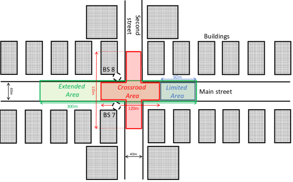
In this section, the performance of the proposed DNN, implemented using the PyTorch DL framework, is numerically evaluated. To analyse how the DNN performance evolves with the environment, three types of datasets covering different areas are considered, as illustrated in Fig. 5:
-
1.
Limited Area: small area of possible user positions in the main street, with base station number as the transmitter. The “active_user_first” (AUF) and “active_user_last” (AUL) deepMIMO parameters are set to and .
-
2.
Extended Area: larger area than the limited one, with possible user positions in the main street, with , , and base station number as the transmitter.
-
3.
Crossroad Area: area located at the intersection of the two streets, with users coming from every direction ( positions). Three deepMIMO channel environments have been generated and concatenated to obtain this last dataset. The first environment uses , , the second uses , and the third uses , . For all these models, the base station number corresponds to the transmitter.
The size of the DNN dataset is set to samples for each scenario, with 85% of the samples used for training as training set and the remaining ones are used to evaluate the performance as test set. Table II shows the chosen hyperparameters which have been used for the proposed multi-tasking DNN.
| Parameter | Set Value |
|---|---|
| Mini-batch size | 500 |
| Initial learning rate | 0.001 |
| ReduceLROnPlateau (factor) | 0.1 |
| ReduceLROnPlateau (patience) | 3 |
| Weight decay | |
| Dropout keep probability | .95 |
| Kernel size | 3 |
| Zero padding | 1 |
| “” in BatchNorm (1D&2D) |
VI-A Sum-Rate Evaluation for All Areas
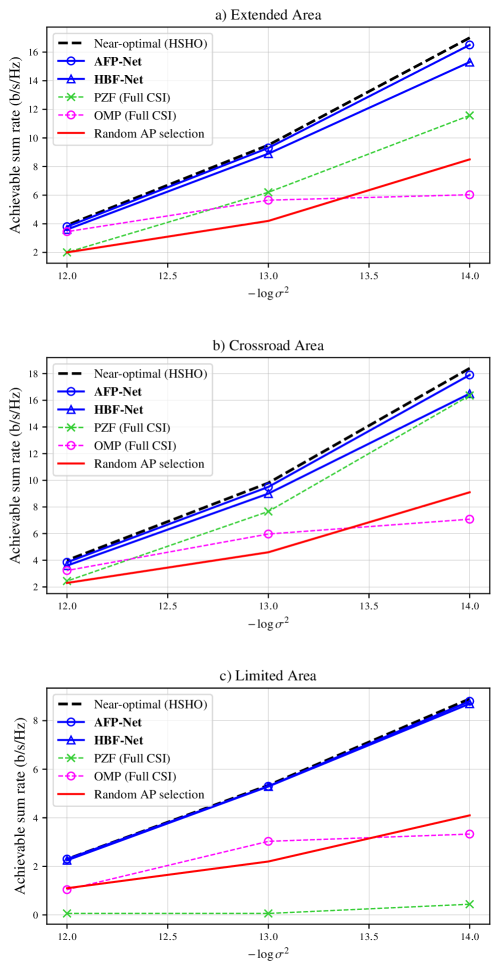
We consider a system with users communicating with a BS equipped with antennas, RF chains, and full precision RSSIs are fedback to the BS. Fig. 6 shows the achievable sum-rate for each considered area when considering different noise power values ranging from dBW to dBW. When considering the channel attenuation, the average SNRs for dBW in Extended Area are dB, dB and dB, in Crossroad Area are dB, dB and dB, and in Limited Area are dB, dB and dB, respectively. It can be seen that the AFP-Net has better performance when compared to the HBF-Net. It is owing to the fact that in the AFP-Net, the digital precoder is extracted from the predicted FDP and HBF based on (18). Therefore, the alignment between analog and digital precoder is preserved. In fact, the sum-rate performance of the AFP-Net is very close to the upper bound obtained by using the full-CSI HBF design method presented in Section III-D.
Furthermore, as shown in Fig. 6 the two proposed unsupervised HBF design methods presented in Section V have better sum-rate performance, for all three areas, when compared with the phase zero forcing (PZF) [11] and the Orthogonal Matching Pursuit (OMP) [4] full CSI techniques. The OMP technique uses as inputs the optimal fully digital precoder and the same AP codebook used by the DNN and designed according to the method proposed in Section IV. In fact, the PZF has very poor performance for the Limited Area, which is located far from BS, and therefore suffers at low SNR level. Unlike PZF which has good performance in high SNR, OMP achieves better sum-rate in low SNR. However, our proposed near-optimal HSHO solution and unsupervised learning DNN methods have stable performance in all SNRs. For instance, with dBW, our proposed method in AFP-Net is better than PZF by 50%, 25% and 8733% for scenario (a), (b) and (c), respectively, and better than OMP by 66%, 59% and 75%. It is worth mentioning that both PZF and OMP techniques require perfect knowledge of the CSI, and therefore require a high bandwidth feedback channel to report the full CSI in FDD scenario, which penalizes the spectral efficiency of the system.
The “Random AP selection” curves in Fig. 6 show the achieved sum-rate when the BS selects the AP from the codebook randomly, while obtaining the DP by substituting into (18) the random AP and the FDP predicted by AFP-Net. The significant performance degradation observed for the Random AP selection confirms that the AP task of the DNN actually learns the system characteristics from the dataset.
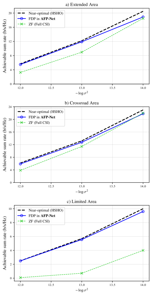
Likewise, Fig. 7 shows that the sum-rate performance of the FDP obtained with the proposed AFP-Net method outperforms the zero forcing (ZF) method, for all areas and different noise power. In fact, the proposed unsupervised learning in AFP-Net has near-optimal FDP sum-rate performance in all selected areas. This make the proposed network a promising solution for FDP design in mm-wave massive MIMO systems.
VI-B Impact of The RSSI Length and Quantization
The effect of the number of SSBs (also the number of RSSI values) on AFP-Net is shown in Fig. 8, for the “Extended Area” scenario. Increasing increases the amount of CSI available to the DNN, and we see that the achievable rate indeed improves as increases. However, increasing also reduces the channel efficiency because of the need to send more SSBs in Step . Furthermore we see that the performance of AFP-Net with is close to the performance obtained with and .
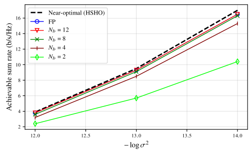
In Fig. 9 we examined the proposed methods with different numbers of quantization bits for the RSSIs, computed using (3). The “Extended Area” is considered to evaluate the performance. In fact, there is a trade-off between the spectral efficiency improvement of the system and the performance of the DNN when changing the number of bits. It can be seen in Fig. 9 that the sum-rate performance of the DNN for to is very close to the DNN performance when considering full precision for the RSSIs.
VI-C Impact of The Number of Users and Antennas
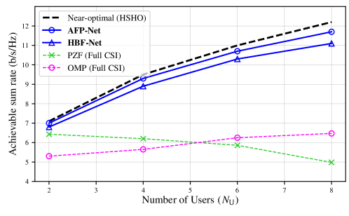
This section evaluates how the performance of the two proposed HBF designs scale when varying the number of users and the number of antennas . The number of RSSIs is set to , the noise power is fixed to dBW and the “Extended Area” is considered. In fact, the complexity of the DNN, measured in terms of the number of parameters, can be expected to depend on the complexity of the optimization problem. Thus increasing the number of antennas in BS or the number of users should require a more complex DNN. However, the results in Figures 10 and 11 show that the proposed architecture is complex enough to have excellent performance for a wide variety of number of antennas and number of users. Fig. 10 shows that although our method is RSSI based, it has better performance in comparison with other CSI-based methods and the sum-rate performance scale with the number of users. For instance, our proposed method is better than PZF by 50%, 84% and 122% for , respectively. Meanwhile, the PZF and OMP method do not scale well when the number of users increases. This can be explained by the fact that increasing the number of user and fixing the number of antennas in BS will generate more inter-user interference. Furthermore, PZF only provides near-optimal results if the ratio between the number of antennas and the number of users is large enough in massive MIMO systems. By increasing the number of users, this ratio decreases and the sum-rate performance of PZF collapses.
In Fig. 11, we evaluate our proposed method with different number of antennas in BS (). Again, we consider the “Extended Area” scenario where dBW, and . As we can see, the PZF method has poor performance when the number of antennas is low whereas the sum-rate performance is near-optimal when the number of antennas grows up to . Therefore, our proposed methods outperforms PZF for the , and antennas cases by 195%, 100% and 50%, respectively. Unlike OMP which has fair enough performance with a small number of antennas, the sum-rate of PZF is almost the same as our proposal for higher number of antenna. However, it is worth mentioning that PZF and OMP require perfect knowledge of the CSI and by increasing the number of antennas in BS it reduces the spectral efficiency whereas our proposed methods only exploit RSSI measurements which we kept to and can therefore significantly improve the data rate of the system by reducing the signaling overhead. To clarify, in where the proposed method and PZF have almost same performance, our proposed method requires bits to feedback the RSSIs where . On the other hand, PZF in same configuration requires to feedback the CSI to the BS where we find that to keep the sum-rate same as fully precision. As a result, in same configuration and sum-rate performance, PZF requires times more feedback bits in comparison with our proposed method.
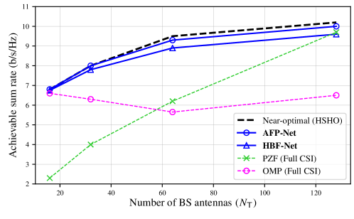
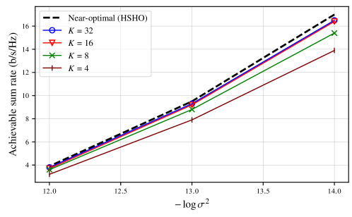
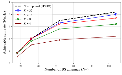
Fig. 12 shows how the number of RSSI measurements affects the sum-rate performance when the number of antennas is increased. It can be seen that the required number of RSSIs to achieve near-optimal sum-rate depends on the number of antenna. For instance, with using or even , the DNN has similar performance as larger number of RSSI such as or . However, for larger number of antennas, the DNN needs more information to design the HBF and as a result more RSSIs transmission are required.
VII Conclusion
Hybrid beamforming is an essential technology for massive MIMO systems that allows to reduce the number of RF chains and therefore increase the energy efficiency of the system. However, the design of digital and analog precoders is challenging, and the estimation of the CSI introduces important signaling overhead, especially in FDD communication. To alleviate this issue, we instead proposed to rely on RSSI feedback, improving the spectral efficiency of the communication system. The SS burst was efficiently designed so that the RSSIs provide maximum information about the CSI. We then proposed to design the hybrid beamforming by using unsupervised deep-learning methods. This unsupervised learning approach leads to decreased training time and cost since the system can be trained using only channel measurements without the costly need to obtain optimal solutions. The deep-learning methods select the AP from a codebook designed to reduce the complexity without sacrificing the sum-rate performance. Finally, the performance of the proposed algorithm was evaluated using the realistic deepMIMO channel model. The results demonstrate that, despite not having access to the full CSI, the BS can be trained to robustly design the hybrid beamforming while achieving a similar sum-rate as the HSHO near-optimal hybrid precoder that was introduced as a benchmark. Moreover, the proposed method can be implemented in real-time systems thanks to its low computational complexity.
References
- [1] J. G. Andrews, S. Buzzi, W. Choi, S. V. Hanly, A. Lozano, A. C. Soong, and J. C. Zhang, “What will 5G be?” IEEE Journal on Selected Areas in Communications, vol. 32, no. 6, pp. 1065–1082, 2014.
- [2] T. L. Marzetta, “Noncooperative cellular wireless with unlimited numbers of base station antennas,” IEEE Transactions on Wireless Communications, vol. 9, no. 11, pp. 3590–3600, 2010.
- [3] A. F. Molisch, V. V. Ratnam, S. Han, Z. Li, S. L. H. Nguyen, L. Li, and K. Haneda, “Hybrid Beamforming for Massive MIMO: A Survey,” IEEE Communications Magazine, vol. 55, no. 9, pp. 134–141, 2017.
- [4] O. E. Ayach, S. Rajagopal, S. Abu-Surra, Z. Pi, and R. W. Heath, “Spatially sparse precoding in millimeter wave MIMO systems,” IEEE Transactions on Wireless Communications, vol. 13, no. 3, pp. 1499–1513, 2014.
- [5] F. Sohrabi and W. Yu, “Hybrid Digital and Analog Beamforming Design for Large-Scale Antenna Arrays,” IEEE Journal on Selected Topics in Signal Processing, vol. 10, no. 3, pp. 501–513, 2016.
- [6] S. Han, C. L. I, Z. Xu, and C. Rowell, “Large-scale antenna systems with hybrid analog and digital beamforming for millimeter wave 5G,” IEEE Communications Magazine, vol. 53, no. 1, pp. 186–194, 2015.
- [7] A. Alkhateeb, O. El Ayach, G. Leus, and R. W. Heath, “Channel estimation and hybrid precoding for millimeter wave cellular systems,” IEEE Journal on Selected Topics in Signal Processing, vol. 8, no. 5, pp. 831–846, 2014.
- [8] F. Sohrabi and W. Yu, “Hybrid Analog and Digital Beamforming for mmWave OFDM Large-Scale Antenna Arrays,” IEEE Journal on Selected Areas in Communications, vol. 35, no. 7, pp. 1432–1443, 2017.
- [9] K. Venugopal, A. Alkhateeb, N. Gonzalez Prelcic, and R. W. Heath, “Channel Estimation for Hybrid Architecture-Based Wideband Millimeter Wave Systems,” IEEE Journal on Selected Areas in Communications, vol. 35, no. 9, pp. 1996–2009, 2017.
- [10] D. Zhu, B. Li, and P. Liang, “A Novel Hybrid Beamforming Algorithm with Unified Analog Beamforming by Subspace Construction Based on Partial CSI for Massive MIMO-OFDM Systems,” IEEE Transactions on Communications, vol. 65, no. 2, pp. 594–607, 2017.
- [11] L. Liang, W. Xu, and X. Dong, “Low-complexity hybrid precoding in massive multiuser MIMO systems,” IEEE Wireless Communications Letters, vol. 3, no. 6, pp. 653–656, 2014.
- [12] E. Björnson, E. G. Larsson, and T. L. Marzetta, “Massive MIMO: Ten myths and one critical question,” IEEE Communications Magazine, vol. 54, no. 2, pp. 114–123, 2016.
- [13] T. Wang, C. K. Wen, H. Wang, F. Gao, T. Jiang, and S. Jin, “Deep learning for wireless physical layer: Opportunities and challenges,” China Communications, vol. 14, no. 11, pp. 92–111, 2017.
- [14] T. O’Shea and J. Hoydis, “An Introduction to Deep Learning for the Physical Layer,” IEEE Transactions on Cognitive Communications and Networking, vol. 3, no. 4, pp. 563–575, 2017.
- [15] P. Dong, H. Zhang, G. Y. Li, I. S. Gaspar, and N. Naderializadeh, “Deep CNN-Based Channel Estimation for mmWave Massive MIMO Systems,” IEEE Journal on Selected Topics in Signal Processing, vol. 13, no. 5, pp. 989–1000, 2019.
- [16] C. B. Ha and H. K. Song, “Signal Detection Scheme Based on Adaptive Ensemble Deep Learning Model,” IEEE Access, vol. 6, pp. 21 342–21 349, 2018.
- [17] W. Xia, G. Zheng, Y. Zhu, J. Zhang, J. Wang, and A. P. Petropulu, “A deep learning framework for optimization of MISO downlink beamforming,” IEEE Transactions on Communications, vol. 68, no. 3, pp. 1866–1880, 2020. [Online]. Available: http://arxiv.org/abs/1901.00354
- [18] X. Li and A. Alkhateeb, “Deep Learning for Direct Hybrid Precoding in Millimeter Wave Massive MIMO Systems,” Conference Record - Asilomar Conference on Signals, Systems and Computers, vol. 2019-Novem, pp. 800–805, 2019. [Online]. Available: http://dx.doi.org/10.1109/IEEECONF44664.2019.9048966
- [19] H. Huang, Y. Song, J. Yang, G. Gui, and F. Adachi, “Deep-Learning-Based Millimeter-Wave Massive MIMO for Hybrid Precoding,” IEEE Transactions on Vehicular Technology, vol. 68, no. 3, pp. 3027–3032, 2019.
- [20] A. Alkhateeb, S. Alex, P. Varkey, Y. Li, Q. Qu, and D. Tujkovic, “Deep learning coordinated beamforming for Highly-Mobile millimeter wave systems,” IEEE Access, vol. 6, pp. 37 328–37 348, 2018.
- [21] A. M. Elbir and A. K. Papazafeiropoulos, “Hybrid Precoding for Multiuser Millimeter Wave Massive MIMO Systems: A Deep Learning Approach,” IEEE Transactions on Vehicular Technology, vol. 69, no. 1, pp. 552–563, 2020.
- [22] H. Hojatian, V. N. Ha, J. Nadal, J.-F. Frigon, and F. Leduc-Primeau, “RSSI-Based Hybrid Beamforming Design with Deep Learning,” in 2020 IEEE International Conference on Communications (ICC): Wireless Communications Symposium (IEEE ICC’20 - WC Symposium), Dublin, Ireland, 2020. [Online]. Available: http://arxiv.org/abs/2003.06042
- [23] A. Alkhateeb, “DeepMIMO: A Generic Deep Learning Dataset for Millimeter Wave and Massive MIMO Applications,” in Proc. of Information Theory and Applications Workshop (ITA), San Diego, CA, 2019, pp. 1–8. [Online]. Available: http://arxiv.org/abs/1902.06435
- [24] E. Bjornson, M. Bengtsson, and B. Ottersten, “Optimal multiuser transmit beamforming: A difficult problem with a simple solution structure [Lecture Notes],” IEEE Signal Processing Magazine, vol. 31, no. 4, pp. 142–148, 2014.
- [25] C. Lin and Q. Feng, “The standard particle swarm optimization algorithm convergence analysis and parameter selection,” Proceedings - Third International Conference on Natural Computation, ICNC 2007, vol. 3, no. 6, pp. 823–826, 2007. [Online]. Available: http://www.sciencedirect.com/science/article/pii/S0020019002004477
- [26] E. Telatar, “Capacity of multi-antenna Gaussian channels,” European Transactions on Telecommunications, vol. 10, no. 6, pp. 585–595, 1999.
- [27] D. Whitley, “A genetic algorithm tutorial,” Statistics and Computing, vol. 4, no. 2, pp. 65–85, 1994. [Online]. Available: https://doi.org/10.1007/BF00175354
- [28] S. Ruder, “An Overview of Multi-Task Learning in Deep Neural Networks,” CoRR, vol. abs/1706.0, 2017. [Online]. Available: http://arxiv.org/abs/1706.05098
- [29] S. Ioffe and C. Szegedy, “Batch normalization: Accelerating deep network training by reducing internal covariate shift,” 32nd International Conference on Machine Learning, ICML 2015, vol. 1, pp. 448–456, 2015. [Online]. Available: http://arxiv.org/abs/1502.03167
- [30] N. Srivastava, G. Hinton, A. Krizhevsky, I. Sutskever, and R. Salakhutdinov, “Dropout: A simple way to prevent neural networks from overfitting,” Journal of Machine Learning Research, vol. 15, no. 1, pp. 1929–1958, 2014.
- [31] L. Lu, Y. Shin, Y. Su, and G. E. Karniadakis, “Dying ReLU and Initialization: Theory and Numerical Examples,” 2019. [Online]. Available: http://arxiv.org/abs/1903.06733
- [32] D. P. Kingma and J. L. Ba, “Adam: A method for stochastic optimization,” 3rd International Conference on Learning Representations, ICLR 2015 - Conference Track Proceedings, 2015. [Online]. Available: https://arxiv.org/abs/1412.6980
- [33] L. Tornheim, “Inversion of a complex matrix,” Communications of the ACM, vol. 4, no. 9, p. 398, 1961. [Online]. Available: https://doi.org/10.1145/366696.366770