Comprehending finger flexor tendon pulley system using
a computational analysis
Abstract
Existing prosthetic/orthotic designs are rarely based on kinetostatics of a biological finger, especially its tendon-pulley system (TPS) which helps render a set of extraordinary functionalities. Studies on computational models or cadaver experiments do exist. However, they provide little information on TPS configurations that lead to lower tendon tension, bowstringing, and pulley stresses, all of which a biological finger may be employing after all. A priori knowledge of such configurations and associated trade-offs is helpful not only from the design viewpoint of, say, an exoskeleton but also for surgical reconstruction procedures. We present a parametric study to determine optimal TPS configurations for the flexor mechanism. A compliant, flexure-based computational model is developed and simulated using the pseudo rigid body method, with various combinations of pulley/tendon attachment point locations, pulley heights, and widths. Deductions are drawn from the data collected to recommend the most suitable configuration. Many aspects of the biological TPS configuration are explained through the presented analysis. We reckon that the analytical approach herein will be useful in arriving at customized (optimized) hand exoskeletal designs.
keywords:
Tendon-pulley system, finger biomechanical model, finger flexion, bionic hand devices1 Introduction
Nature has gifted human fingers with the ability to perform extraordinarily diverse movements that are combinations of the four basic types- flexion, extension, and ad/abduction. Anatomically, flexor tendon pulley system (TPS) and extensor mechanism are responsible for transferring power from respective muscles to phalangeal bones, to perform these movements. In case of injury or post-stroke cognitive impairment, the patient may need TPS reconstruction surgery or artificial devices depending on cases and severity. Therefore, it is crucial to understand the biomechanics of the TPS involved.
Flexion-extension mechanics of a finger is studied mainly in two ways: by (i) performing surgical procedures on cadaver hands, and (ii) using computational models. Computational models provide a non-destructive alternative to studies using cadaver hands thereby reducing the number of cadaver surgeries required. Given the complex anatomy of the hand, developing an accurate and generic model is still being actively researched and remains a challenging task.
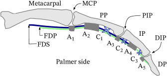
Several studies exist on the role of each pulley and tendon in the flexor TPS (Fig. 1). Among annular pulleys, A2 is the widest, followed by A4. Stress in pulley fibers depend on pulley location and width. High pulley stress can cause discomfort in finger movement (Schweizer [2008]). Some cadaver studies suggest that smaller width of A2 and A4 pulleys can be used without compromising much on the flexion range (Mitsionis et al. [1999], Chow et al. [2014], Leeflang and Coert [2014]). Those by Solonen and Hoyer [1967] and Hume et al. [1991] that employ computational models contradict on the effect of change in pulley positions. Loosening/removal of pulleys can cause bowstringing (i.e., tendon moving away from bones during flexion-extension), which reduces the range of flexion (ROF), creating difficulty in forming a fist, or grasping (Dy and Daluiski [2013], Brand et al. [1975]). While designing artificial systems or performing TPS reconstruction surgery, proper knowledge of pulley locations, widths, and heights (i.e., loosening), and, exclusion of pulleys/tendon if required and the trade-offs involved, will help make the best possible decisions.
Existing literature does not focus much on the tendon tension requirement for finger flexion. It is desirable to have the highest range of flexion (ROF) for a given tendon tension for the corresponding muscle load to be reduced. This is even more critical when designing bionic artificial devices, as, selection of actuators, and battery power requirements would pose a limit on this tension. This paper presents a parametric study to arrive at optimal flexor TPS configurations, which maximizes ROF while keeping bowstringing and pulley stress as small as possible. We also investigate whether having both FDS and FDP tendons improves the flexion range, or one can be ignored to simplify the design of an artificial device without significant loss in functionality.
The paper is organized as follows. The computational biomechanical model developed is presented in section 2. Parametric study and results are described in section 3. TPS configurations are recommended and comparisons with the biological finger made in section 4, followed by conclusion in section 5.
2 Methods
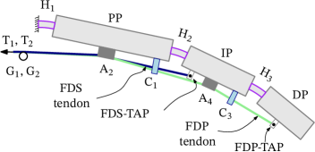
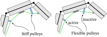
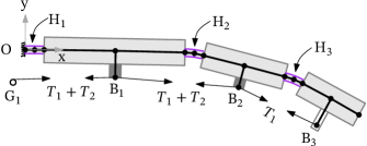
We modeled the flexor mechanism of an index finger111Index finger is the most dexterous among all four fingers, and is, therefore, a good choice for framing a generic model. as a beam-string arrangement described in Fig. 3. Human finger joints have non-fixed axes of rotation and inherent stiffnesses (van Nierop et al. [2008]). Hence, we modeled them as flexure hinges which possess similar deformation characteristics (Guo and Lee [2013]). Biological finger tendons experience minimal strain (Pring et al. [1985]), and thus, were modeled as inextensible strings. C–pulleys are cross-shaped (cruciate), flexible–inextensible, and remain loose unless pulled by a tendon. We implemented these characteristics through flexible–inextensible string loops (Fig. 3).
2.1 Mathematical Formulation
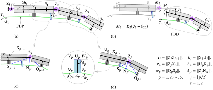
For full range flexion, the flexure hinges must undergo large bending deflection with small strain. A 2R or 3R pseudo-rigid-body model (PRBM) of such a flexure is computationally simpler than the nonlinear finite element method (FEM), and gives much smaller approximation error compared to a 1R PRBM (Su [2009] and Yu et al. [2012]). Nevertheless, we chose 1R PRBM because (i) in our analysis, it gave results sufficiently close to those from FEM and the experiments performed (A and B), and (ii) this study concerns only with relative responses of different TPS configurations. The proposed model of the overall TPS is thus, 3R, as shown in Fig. 4a. We assumed that the finger moves slowly while changing its posture. Hence, joint velocities and accelerations were considered zero. All external (contact and non-contact) forces were assumed absent. Friction was neglected in tendon-pulley contacts. With these assumptions, governing equations of the quasistatic system can be written from Fig. 4b as:
| (1) |
where, is the stiffness and is the neutral position of the torsional spring at joint. Here, identify the three joints MCP, PIP, and DIP (and the three phalanges PP, IP, and DP), respectively. is the corresponding joint angle. Moment arm at the joint is (Solonen and Hoyer [1967]) for tendon tension , as shown in Fig. 4c–d. Indices correspond to FDP and FDS tendons, respectively. Since FDS tendon does not exert moment on the DIP joint, the moment arm was set to zero. Moment arm can be computed in terms of the TPS parameters, as follows.
Let denote the sequence of pulleys/TAPs in which they are connected with a given tendon. Ground pulley is always indexed as 0. As an example, and for pulleys C1 and A2 , respectively, if pulley C1 is proximal to pulley A2. This indexing is performed independently for the two tendons. Let , , and be relative position, width, and height of pulley (Fig. 4). The pulley end is marked with points Qp, Rp (midpoint), and Sp (Fig. 4d) occupying positions and , respectively. Let joint (Zj) occupy position . Using complex algebra, we may write:
| (2) |
Here, and are length and nominal bone-width of phalange, respectively. We assumed for stiff pulleys. If the flexible-inextensible C–pulley is active, as in Figs. 3 and 4d, it orients itself along the angle bisector of the two segments of tendon in contact. This ensures zero bending moment in that C–pulley. Hence, the correponding angle is solved by minimizing the following objective:
| (3) |
where, and are angles with the pulley direction (UpRp) made by the left and right tendon segments (QpSp-1) and (SpQp+1), respectively, as shown in Fig. 4d (enlarged view). For a flexible pulley indexed , and can be expressed in terms of pulley parameters and joint angles as follows:
| (4) |
pulley becomes active when the shortest distance of the tendon segment Sp-1Qp+1 from the base Up becomes equal to or smaller than the pulley height. In that case, the moment arm base Njt lies on SpQp+1, otherwise on Sp-1Qp+1. In case flexible pulley is located distally relative to the joint, Njt lies on Sp-1Qp when the pulley is active, and Sp-1Qp+1 otherwise.
Point Njt () on the nearest segment SξQη ( or , or ) can be found using the following two conditions:
(i) ZjNjt SξQη implying:
| (5) |
(ii) Njt lies on the line SξQη. Therefore,
| (6) |
where . Solving these two equations yields:
| (7) | ||||
| (8) |
To obtain flexion response of the TPS, we incremented tensions and T2 in a given ratio , and solved Eqs. (1) for joint angles at each step (Fig. 5). For this, we employed the trust-region-dogleg optimization algorithm via the fsolve() implementation of MATLAB. We also simulated the joint rotation limits of a biological finger during flexion. Physically, interphalangeal contact invalidates the equation corresponding to the locked joint in the set (1). Therefore, we dropped that equation and solved others for the remaining unknown joint angles and the tendon tensions. In case two or more joints locked in the same -step, we found the joint that locked at the lowest tension in that incremental step, and recorded only the corresponding state of the TPS.
2.2 Finger flexion, Bowstringing, and Pulley stress
We quantified flexion by the sum . For two different TPS configurations, identical values of need not imply that the joints angles are also identical. Still, indicates the amount of finger curl and is, therefore, a useful quantity to compare TPS configurations. Bowstringing at a joint was quantified as the shortest distance between the joint and a tendon. For instance, bowstringing at PIP joint () due to FDP tendon (), when C1 pulley () is active, is:
| (9) | |||
We defined as the critical value . We computed axial and bending stresses on a pulley (the enlarged view, Fig. 4d) due to FDP and FDS tendons as follows:
| (10) |
where, , , and are the height, width, depth and area moment of inertia of the pulley. The maximum resultant stress exists at either Vp or Wp on the pulley base (Fig. 4d), where bending stress is maximum. When computing stresses in flexible-inelastic pulleys, the pulley-width is assumed to remain even when pulley bends, and the pulley tip-line QS normal to the pulley length RU. This works well for pulleys of small widths. Biologically, FDS tendon terminates just proximally to the A4 pulley. Likewise, it may not interact with pulleys A4 and C3 if they are located distally to FDS-TAP in a candidate TPS configuration. In that case, we substitute = 0 for them in Eqs. (10). We defined the highest among all pulleys as the critical value .
3 Results
| Constants | Values | Constants | Values | Constants | Values | Constants | Values | |||
|---|---|---|---|---|---|---|---|---|---|---|
| 0.95 | 42.0 | 0 | 90∘ | |||||||
| 0.60 | 27.0 | 0 | 100∘ | |||||||
| 0.60 | 19.5 | 0 | 80∘ | |||||||
| 0.5 | 1.0 | |||||||||
| 10.0 | 7.0 | 8.0 | 200 | |||||||
| 5.0 | 4.0 |
| ROF at | TPS | Refer to marked | ||||||||
|---|---|---|---|---|---|---|---|---|---|---|
| 5 N | 8 N | Configuration | (mm) | (MPa) | (mm) | (mm) | (mm) | (mm) | (mm) | curves in figures |
| 251∘ | †270∘ | C=C=C | † | † | 2.0 | 2.0 | , Fig. 12 | |||
| 252∘ | †270∘ | C=C=D | † | † | 2.0 | 2.0 | , Fig. 12 | |||
| 176∘ | 256∘ | C–C–C | 2.0 | , Fig. 10(b), , Fig. 10(d) | ||||||
| 176∘ | 256∘ | C–C–C | 2.0 | 2.0 | , Fig. 12 | |||||
| 176∘ | 256∘ | C–C–D | 2.0 | 2.0 | , Fig. 12 | |||||
| 200∘ | 256∘ | C–C–C | 4.5 | , Fig. 10(a) | ||||||
| 200∘ | 256∘ | C–C–C | – | – | 8.0 | – | , Fig. 10(c) | |||
| 223∘ | 256∘ | C–C–C | – | – | 2.0 | – | , Fig. 10(c) | |||
| 223∘ | 256∘ | C–C–D | – | – | , Fig. 9b, 9b, 9b | |||||
| 223∘ | 256∘ | C–C–C | – | – | – | , Fig. 9b, 9b, 9b | ||||
| 223∘ | 256∘ | C–C–C | – | – | 0.5 | – | , Fig. 10(c) | |||
| 224∘ | 255∘ | C–C–C | – | 2.0 | – | – | , Fig. 10(d) | |||
| 226∘ | 254∘ | C–C–C | – | 3.5 | – | – | , Fig. 10(d) | |||
| 177∘ | 252∘ | C–C–C | 2.0 | 2.0 | , Fig. 10(d) | |||||
| 200∘ | 250∘ | C–C–C | 2.0 | – | ||||||
| 148∘ | 247∘ | C–C–C | 8.0 | , Fig. 10(c) | ||||||
| 166∘ | 246∘ | CD–CD–C | 2.0 | , Fig. 10(b) | ||||||
| 176∘ | 246∘ | C–C–C | 3.5 | 2.0 | , Fig. 10(d) | |||||
| 184∘ | 246∘ | C–D–P | – | – | , Fig. 9b, 9b, 9b | |||||
| 151∘ | 245∘ | C–C–C | 2.0 | , Fig. 10(c) | ||||||
| 151∘ | 245∘ | C–C–C | 0.5 | , Fig. 10(c) | ||||||
| 187∘ | 243∘ | C–D–C | – | – | , Fig. 9b, 9b, 9b | |||||
| 187∘ | 242∘ | C–C–P | – | – | , Fig. 9b, 9b, 9b | |||||
| 187∘ | 242∘ | C–D–D | – | – | , Fig. 9b, 9b, 9b | |||||
| 114∘ | 176∘ | C–C– | 2.0 | 2.0 | , Fig. 12 | |||||
| 143∘ | 176∘ | C–C– | – | – | – | , Fig. 11b, 11c, 11d | ||||
| 143∘ | 176∘ | C–D– | – | – | , Fig. 11b, 11c, 11d | |||||
| 114∘ | 174∘ | C–D– | 2.0 | 2.0 | , Fig. 12 | |||||

Using the 3R PRBM, we determined the effect of TPS parameters on the range of flexion (ROF) and critical values of bowstringing and pulley stresses . Various finger model data used in the PRBM are listed in Tab. 2 and results are summarized in Tab. 2.
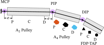
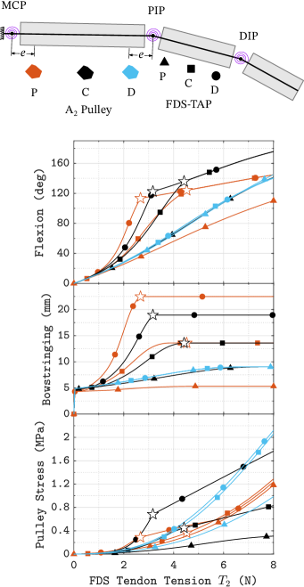
To explain the observations, we qualified pulleys and TAPs as proximal (P), central (C), or distal (D) based on their locations on the respective phalanges (Fig. 6). We also named TPS configurations using the characters P, C, and D in groups separated by hyphens (–) or double hyphens (=). The leftmost group describes pulleys on the proximal phalange. The rightmost character describes TAP. For example, C–D–P indicates one central pulley on the proximal phalange, one distal pulley on the intermediate phalange, and proximal FDP-TAP on the distal phalange. A hyphen (–) indicates that only one tendon is active, whereas double-hyphen (=) indicates that both FDP and FDS tendons are active. In the above example, only FDP tendon is active. Another example C–C– implying nothing on the distal phalange, indicates FDS tendon, with central pulley on the proximal phalange and central FDS-TAP on the intermediate phalange. C=CD=C indicates one central and one proximal pulley on the proximal phalange, and one central and one distal pulley on the intermediate phalange. Both tendons are active. Further, tilde over P indicates that the corresponding pulley is flexible–inextensible. In each group, the second character is for a C–pulley. The rest are for A–pulleys/TAPs.
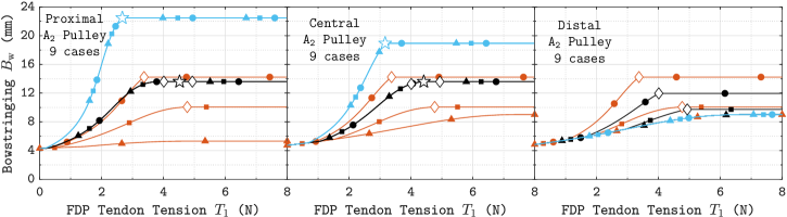
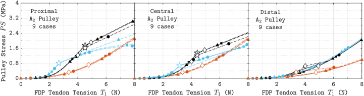
To understand the effect of pulley/TAP locations, we analyzed the case of FDP tendon with one pulley per phalange. We considered 27 TPS configurations, formed from three candidate locations each, of pulleys A2 and A4, and the FDP–TAP, as described in Fig. 6. The pulley heights, widths and offsets used were the default values , , and , respectively, given in Tab. 2. In these simulations, TPS configurations C–C–C and C–C–D yield the highest ROF of at tendon tension, with 13.6 mm bowstringing and pulley stresses of 2.4 and 2.2 MPa, respectively (Fig. 9b–9b). The pulley A4 experiences higher stress than the pulley A2 (0.8 MPa; Fig. 9b).
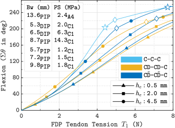
To reduce , we added pulleys C1 and C3 of width at distal locations with offset on proximal and intermediate phalanges, respectively. This TPS configuration CD–CD–C with stiff C–pulleys of 2 mm height yields bowstringing of 6.5 mm, flexion range of , and pulley sress 6.3 MPa (Fig. 10(a)). With C-pulley height of 4.5 mm, bowstringing of 8.7 mm, flexion range of , and pulley stress of 14.3 MPa are obtained. Replacing stiff C–pulleys by flexible-inelastic ones increases flexion range to with 2 mm C-pulley height, and to with 4.5 mm C-pulley height. Pulley stress remains below MPa for pulley height mm, and bowstringing below 9.8 mm. Positioning the flexible C–pulleys of height mm at an offset from joints (Fig. 6), i.e., 10% of the respective bone lengths, increases flexion range to (Fig. 10(b)). Bowstringing becomes 8.9 mm. With proximal C–pulleys, as in TPS configuration C–C–C, flexion range is smaller, and bowstringing and pulley stresses are higher (Tab. 2).
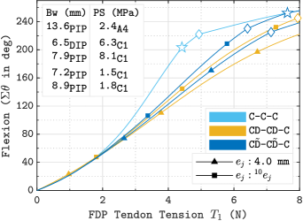
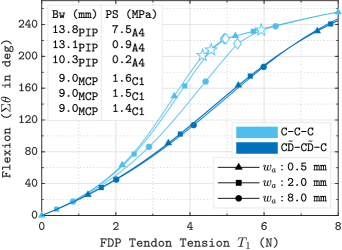
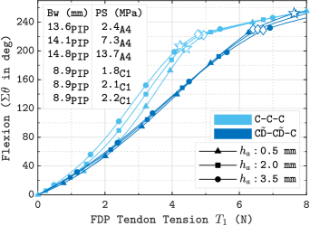
Without C–pulleys, increasing widths of pulleys A2 and A4 from 0.5 mm (very thin) to 2 mm reduces pulley stress from 7.5 MPa to 0.9 MPa, without affecting flexion range much (Fig. 10(c), Tab. 2). Increasing heights of pulleys A2 and A4 with width , from 0.5 mm to 3.5 mm, increases the pulley stress from 2.4 MPa to 13.7 MPa (Fig. 10(d)). Flexion range does not change much, while bowstringing increases from 13.6 mm to 14.8 mm. In presence of flexible C–pulleys, the pulley stress increases from 1.8 MPa to 2.2 MPa, while bowstringing remains unaffected (Fig. 10(d)). The flexion range decreases from 256∘ to 246∘.
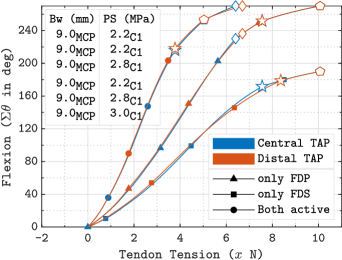
To study the FDS-TPS, we analyzed case of the FDS tendon with one-pulley per phalange. Figure 11a describes nine TPS configurations, formed from three candidate positions of A2 pulley and FDS—TAP. As observed in Fig. 11b-d, TPS configuration C–C– gives the highest flexion range of , bowstringing of 13.6 mm, and pulley stress of 0.8 MPa. TPS configuration C–D– results in higher bowstringing of 18.9 mm, and higher pulley stress of 1.8 MPa. To reduce bowstringing, we added C1 pulley with offset , width , and height 2 mm. With the resulting TPS configurations C–C– and C–D–, reduces to 9.0 mm, and pulley stress increases to 2.2 and 2.8 MPa respectively, without affecting the flexion range (Tab. 2).
To study the combined actuation of FDP and FDS tendons, we arrived at the common configuration C=C=C, as follows. For highest flexion range, FDP–TPS configurations are C–C–C and C–C–D, and FDS–TPS configurations are C–C– and C–D– (Tab. 2). Both bowstringing and pulley stress are much lower for FDS–TPS configuration C–C–. Hence, we merged it with FDP-TPS configuration C–C–C. When both tendons were actuated in this configuration C=C=C, sharing equal loads, full finger flexion (270∘) was achieved at much lower individual tension of 6.4 N (Fig. 12, Tab. 2). Pulley-stress increased to 2.8 MPa from 2.2 MPa for full flexion with only FDP-tendon achieved at 10.1 N.
Overall, critical bowstringing was observed mostly at MCP or PIP joint, while critical stress at pulley A4 or C1 (Tab. 2).
4 Discussion
Results for FDP-TPS with one pulley per phalange show that pulley locations for high ROF (, Tab. 2) suffer from high bowstringing and high pulley stress. This problem can be addressed without affecting ROF adversely, (i) by adding flexible-inextensible C–pulleys slightly away from joints, and (ii) by either increasing width or decreasing height of annular pulleys or both. Including FDS tendon increases ROF further. We quantified bowstringing mm as small, a limit obtained as sum of bone semi-width 3.5 mm, pulley height 2 mm, and the clearance 3 mm beyond pulley height. The proposed analysis can help gain insight into the biological TPS, and also in selecting optimal TPS designs for bionic devices, discussed next.
4.1 The Biological Tendon Pulley System
We observed that the centrally located annular pulleys A2 and A4 result in very high flexion ranges (Tab. 2), thus agreeing with Dy and Daluiski [2013] and Chow et al. [2014]. Role of flexible-inelastic biological C–pulleys is evident from significant reduction in pulley stress and increase in ROF compared to identical but stiff pulleys (Figs. 10(a) and 10(b)). C–pulleys also lower bowstringing considerably. We also observed that a small increase in the widths of A-pulleys decreases pulley stress significantly (Fig. 10(c)). However, pulley width does not affect ROF much, thus concurring with Mitsionis et al. [1999], Chow et al. [2014], Leeflang and Coert [2014]. To explain why A2 pulley is the widest, we reckon further analysis is necessary.
A slight increase in heights of the annular pulleys increases pulley stress significantly in the absence of C–pulleys (Fig. 10(d)). This result explains why loosening of the main pulleys A2 and A4 during injury is painful when C–pulleys get torn. In this case, high bowstringing is also observed. However, it remains unexplained why ROF reduces in the case of biological TPS. Biologically, FDS–TAP is immediately proximal to pulley A4, and therefore nearly central on IP. Further, both FDP and FDS tendons share the same set of pulleys. Both these aspects can be explained from the observations that FDP-TPS configurations CD–CD–C and FDS-TPS configurations CD–C– yield the highest ROF, with low bowstringing and pulley-stress (Fig. 12).
Most of the above aspects indicate that biological TPS has evolved to maximize ROF with minimum possible actuation tension, bowstringing and pulley stress. Pulleys A1, A3, A5 and C2 in Fig. 1, considered less important in literature, were excluded herein.
4.2 Bionic devices based on tendon-pulley system
Recently, flexure hinges and TPS based robotic hand devices have shown to be useful in rehabilitation and daily assistance of hand-impaired patients (Hofmann et al. [2018], Mutlu et al. [2015]). This study may help improve existing designs by offering the right TPS configuration as per the requirements. To exemplify, consider developing a TPS based hand orthosis with one pulley per phalange and one (FDP) tendon. Results for FDP–TPS at 8 N tendon tension (Figs. 9-9) show that for small bowstringing ( 9 mm), the highest ROF attainable is which can be increased to , if the limit is increased to 10 mm. Thus, only a suboptimal design can be obtained. The same ROF can be obtained if desired, at a lower tendon tension with two pulley per phalange designs. In that case, we recommend the TPS configuration C–C–C with flexible-inelastic C–pulleys of 2 mm height, offset from joints by 10% of the respective bone lengths (Fig. 10(b)). This configuration offers the ROF of at 5.5 N tension and the full ROF (270∘) at 10.1 N tension without compromising on both the bowstringing and pulley stresses. Adding FDS tendon helps achieve the full ROF at a much lower individual tendon tension of 6.4 N (Fig. 12). In this case, two smaller actuators may be used with a control system to distribute the load in both tendons, and thereby generate several finger flexion postures (Fig. 12). However, the design may become bulky and also require a complex control system. A single FDP tendon may be sufficient when designing orthosis for hand open-close exercises, in case forming different hand postures is not essential. In this case, the TPS configuration suggested by Hume et al. [1991] (explained in section 4.3) is also optimal. These examples highlight the importance of the parametric study in choosing an optimal flexor TPS configuration given the design requirements and making aware of the trade-offs needed.
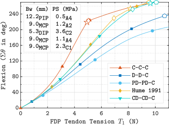
We also analyzed various TPS configurations employed in the existing robotic hands (Fig. 13) and found them mostly suboptimal. These configurations involve only a single (FDP) tendon. FDP–TPS configuration C–C–C used by Delph et al. [2013] and Nycz et al. [2015] suffers from high bowstringing (3.2 mm above the limit). Configuration D–D–C with 2 mm pulley width by Bajaj et al. [2020] results in small bowstringing, but also a much smaller flexion range (225∘ at 10 N). Configuration PD–PD–C by Jung et al. [2009], Xu et al. [2012], and Xu and Todorov [2016] results in even lower flexion range (215∘) and higher pulley stress.
4.3 Comparison with TPS Reconstruction Literature
The average FDP tendon tension in biological fingers for full flexion is 8.15 N (Yang et al. [2016]). When only the FDP tendon is active, nearly full flexion at 8 N FDP tension is observed with FDP-TPS configuration C–C–C (Fig. 12). This reinforces the argument of reconstructing only the FDP tendon, if just one tendon can be repaired (Kotwal and Gupta [2005]). The TPS configuration with two pulleys around each joint at the flare of the metaphysis of the phalangeal bones, of small height as suggested by Hume et al. [1991] for reconstruction surgery, is also observed to be good in our simulations (Fig. 13). High flexion range, in this case, can be attributed to the fact that the two pulleys on each of the proximal and intermediate phalanges behave like a single, very wide pulley located centrally, resulting in the TPS configuration C–C–C. The effectively large width also helps in lowering both pulley stress and bowstringing. Recommendations of Solonen and Hoyer [1967] to use one pulley per phalange near or on joints result in low ROF, as observed in Fig. 9.
4.4 Limitations, Advantages, and Future Scope
Results herein are based on a specific set of finger joint stiffness values (section 3), assuming the fully extended finger as its neutral state. With different sets of stiffnesses and neutral states, the relative positioning of curves corresponding to different TPS configurations is expected to remain similar. Therefore, it may not affect the choice of TPS configuration much. This can be explained geometrically from Fig. 4a based on equilibrium moment-arm variations. Nevertheless, one may need to verify by regenerating all graphs as per her/his finger joint stiffnesses. Some patients having spasticity222 Spasticity is a condition in which fingers are always in the flexed state and resist extension. or otherwise, have either joint neutral positions or joint stiffnesses or both altered. An advantage with the 3R PRBM computational model used herein is that it is readily adaptable in such situations.
This study does not address much on the coordination between FDS and FDP tendons. That requires simulating grasping using contact mechanics, which can provide insight into how the two tendons share the load in forming different finger postures. An extensor mechanism can also be included, as it is known to contribute during grasping.
5 Conclusions
The presented study facilitates choosing an optimal flexor tendon pulley system (TPS) configuration based on one’s design requirements, while also making aware of the trade-offs needed. It also explains several aspects of the biological TPS. This fact validates our study, as well as indicates that the objective of high flexion range with low tendon tension, bowstringing, and pulley stress is in accordance with nature. We also demonstrated that TPS configurations superior to those used in existing hand prosthetic devices could be employed without introducing much additional complexity. Results herein may alter, but only quantitatively, in presence of hand abnormalities through variations in joint stiffnesses and neutral positions.
This study may find applications in – (i) understanding flexion biomechanics of the human finger, (ii) designing cost-effective robotic devices for hand, and (iii) surgery related to tendon pulley reconstruction.
Appendix A Nonlinear Finite Element Model
In the nonlinear finite element method (FEM) formulation, 1D co-rotation frame elements were used which can undergo large bending deflection but permit small strain. The small strain was ensured via sufficiently large number of elements per flexure. Discretization of the model geometry and boundary conditions are shown in Fig. 14. Detailed formulation for 1D co-rotational frame elements based on the works of Crisfield [1993], Belytschko and Hsieh [1973], Belytschko and Glaum [1979] is given in Mankame [2004]. String tensions and ( in FDP and in FDS tendon) at each boundary node B1, B2, and B3 (Fig. 14) are always directed towards the neighbouring nodes lying on the string. This makes the nodal external force vector , i.e., dependent on where is the nodal displacement vector. To solve nonlinear equilibrium equations using the Newton-Raphson technique, with as the force residual where is the nodal internal force vector, the tangent stiffness matrix was computed as
| (11) |
One notes that .]
Appendix B Validation of the computational model
To validate the two computational models, we developed a prototype of the biomechanical model (Fig. 15). C-Pulleys were not included. All three phalanges were 3D-printed (FDM) using ABS plastic (2000 MPa, Young’s modulus), and had the same cross-section (20 mm 6 mm). A neoprene rubber (9 MPa, Young’s modulus) strip of cross-section 11.6 mm 2.1 mm was used as flexure for finger joints. 7.5 mm height (includes bone-width in the model, Fig. 4) was chosen for all pulleys including the guiding pulley, and the TAPs. The guiding pulley G1 location was chosen to be mm (refer Fig. 14).
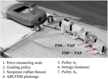
To reduce friction between the platform and the prototype, we embedded a 4 mm carbon-steel ball on each phalange. A pull-type force dynamometer with 2 gf resolution was employed to measure the string tension. To account for measurement errors, we conducted five trials of finger flexion for each of the FDP and FDS tendons. Finally, we compared the mean and standard deviation of the tendon tension and flexion range with the simulation results from both FEM and 3R PRBM.
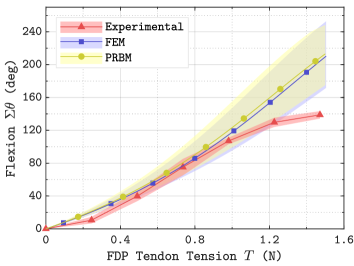
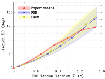
To account for manufacturing tolerances (available rubber strip thickness = 2.1 0.1 mm, width = 11.6 0.1 mm), we simulated the computational model for flexure dimensions in this tolerance band. The strip width was chosen equal to the finger width. The strip thickness was fixed to ensure that flexure stiffness matches that of the respective finger joint. The moment exerted on the right portion of the finger (FBD in Fig. 4b) can be obtained from FEM as the moment at its leftmost node. This moment should be equal to that obtained from PRBM. With this understanding, we performed some trial and error with the strip thickness for each flexure to arrive at its appropriate thickness. Equivalent stiffness of all three joints with the nominal dimensions is . The upper tolerance value corresponds to , whereas the lower one to . PRBM is used to simulate the TPS configuration C–C–C or C–C– for these three stiffness sets. FEM directly uses the highest and lowest dimensions in addition to the nominal dimensions. As a result, we obtained the bands of tension-flexion response as shown in Fig. 16.
All three methods yield very similar results in the limit of standard deviation, up to , at tendon tension of 1.2 N for FDP tendon. After that, the experimental curve diverges, which may be explained by the material nonlinearity associated with the neoprene rubber corresponding to large deflections. Both FEM and PRBM as implemented herein, disregard material nonlinearity. Results for the FDS tendon are similar (Fig. 16(b)).
References
- Bajaj et al. [2020] Bajaj, A., Jain, V., Kumar, P., Unal, A., Saxena, A., 2020. Soft hand exoskeleton for adaptive grasping using a compact differential mechanism, in: Mechanism and Machine Science. Springer, pp. 733–746.
- Belytschko and Glaum [1979] Belytschko, T., Glaum, L.W., 1979. Applications of higher order corotational stretch theories to nonlinear finite element analysis. Computers & Structures 10, 175–182.
- Belytschko and Hsieh [1973] Belytschko, T., Hsieh, B., 1973. Non-linear transient finite element analysis with convected co-ordinates. International Journal for Numerical Methods in Engineering 7, 255–271.
- Brand et al. [1975] Brand, P.W., Cranor, K., Ellis, J., 1975. Tendon and pulleys at the metacarpophalangeal joint of a finger. The Journal of bone and joint surgery. American volume 57, 779–784.
- Chow et al. [2014] Chow, J.C., Sensinger, J., McNeal, D., Chow, B., Amirouche, F., Gonzalez, M., 2014. Importance of proximal a2 and a4 pulleys to maintaining kinematics in the hand: a biomechanical study. Hand 9, 105–111.
- Crisfield [1993] Crisfield, M.A., 1993. Non-linear finite element analysis of solids and structures. volume 1. Wiley New York.
- Delph et al. [2013] Delph, M.A., Fischer, S.A., Gauthier, P.W., Luna, C.H.M., Clancy, E.A., Fischer, G.S., 2013. A soft robotic exomusculature glove with integrated semg sensing for hand rehabilitation, in: 2013 IEEE 13th International Conference on Rehabilitation Robotics (ICORR), IEEE. pp. 1–7.
- Dionysian et al. [2005] Dionysian, E., Kabo, J.M., Dorey, F.J., Meals, R.A., 2005. Proximal interphalangeal joint stiffness: measurement and analysis. The Journal of hand surgery 30, 573–579.
- Dy and Daluiski [2013] Dy, C.J., Daluiski, A., 2013. Flexor pulley reconstruction. Hand clinics 29, 235–242.
- Guo and Lee [2013] Guo, J., Lee, K.M., 2013. Compliant joint design and flexure finger dynamic analysis using an equivalent pin model. Mechanism and Machine Theory 70, 338–353.
- Hofmann et al. [2018] Hofmann, U.A., Bützer, T., Lambercy, O., Gassert, R., 2018. Design and evaluation of a bowden-cable-based remote actuation system for wearable robotics. IEEE Robotics and Automation Letters 3, 2101–2108.
- Hume et al. [1991] Hume, E.L., Hutchinson, D.T., Jaeger, S.A., Hunter, J.M., 1991. Biomechanics of pulley reconstruction. The Journal of hand surgery 16, 722–730.
- Jung et al. [2009] Jung, S.Y., Kang, S.K., Bae, J.H., Moon, I.H., 2009. Design of biomimetic hand prosthesis with tendon-driven five fingers. Journal of Biomedical Engineering Research 30, 205–212.
- Kamper et al. [2002] Kamper, D.G., Hornby, T.G., Rymer, W.Z., 2002. Extrinsic flexor muscles generate concurrent flexion of all three finger joints. Journal of biomechanics 35, 1581–1589.
- Kim et al. [2019] Kim, D.H., Lee, S.W., Park, H.S., 2019. Development of a biomimetic extensor mechanism for restoring normal kinematics of finger movements post-stroke. IEEE Transactions on Neural Systems and Rehabilitation Engineering 27, 2107–2117.
- Kotwal and Gupta [2005] Kotwal, P., Gupta, V., 2005. Neglected tendon and nerve injuries of the hand. Clinical Orthopaedics and Related Research® 431, 66–71.
- Leeflang and Coert [2014] Leeflang, S., Coert, J., 2014. The role of proximal pulleys in preventing tendon bowstringing: pulley rupture and tendon bowstringing. Journal of Plastic, Reconstructive & Aesthetic Surgery 67, 822–827.
- Mankame [2004] Mankame, N.D., 2004. Investigations on contact-aided compliant mechanisms. Ph.D. thesis. University of Pennsylvania.
- Mitsionis et al. [1999] Mitsionis, G., Bastidas, J.A., Grewal, R., Pfaeffle, H.J., Fischer, K.J., Tomaino, M.M., 1999. Feasibility of partial a2 and a4 pulley excision: effect on finger flexor tendon biomechanics. The Journal of hand surgery 24, 310–314.
- Mutlu et al. [2015] Mutlu, R., Alici, G., in het Panhuis, M., Spinks, G., 2015. Effect of flexure hinge type on a 3d printed fully compliant prosthetic finger, in: 2015 IEEE International Conference on Advanced Intelligent Mechatronics (AIM), IEEE. pp. 790–795.
- van Nierop et al. [2008] van Nierop, O.A., van der Helm, A., Overbeeke, K.J., Djajadiningrat, T.J., 2008. A natural human hand model. The Visual Computer 24, 31–44.
- Nycz et al. [2015] Nycz, C.J., Delph, M.A., Fischer, G.S., 2015. Modeling and design of a tendon actuated soft robotic exoskeleton for hemiparetic upper limb rehabilitation, in: 2015 37th Annual International Conference of the IEEE Engineering in Medicine and Biology Society (EMBC), IEEE. pp. 3889–3892.
- Pring et al. [1985] Pring, D., Amis, A., Coombs, R., 1985. The mechanical properties of human flexor tendons in relation to artificial tendons. The Journal of Hand Surgery: British & European Volume 10, 331–336.
- Schulter-Ellis and Lazar [1984] Schulter-Ellis, F.P., Lazar, G.T., 1984. Internal morphology of human phalanges. The Journal of Hand Surgery 9, 490 – 495.
- Schweizer [2008] Schweizer, A., 2008. Biomechanics of the interaction of finger flexor tendons and pulleys in rock climbing. Sports Technology 1, 249–256.
- Solonen and Hoyer [1967] Solonen, K.A., Hoyer, P., 1967. Positioning of the pulley mechanism when reconstructing deep flexor tendons of fingers. Acta Orthopaedica Scandinavica 38, 321–328.
- Su [2009] Su, H.J., 2009. A Pseudorigid-Body 3R Model for Determining Large Deflection of Cantilever Beams Subject to Tip Loads. Journal of Mechanisms and Robotics 1. 021008.
- Xu et al. [2012] Xu, Z., Kumar, V., Matsuoka, Y., Todorov, E., 2012. Design of an anthropomorphic robotic finger system with biomimetic artificial joints, in: 2012 4th IEEE RAS & EMBS International Conference on Biomedical Robotics and Biomechatronics (BioRob), IEEE. pp. 568–574.
- Xu and Todorov [2016] Xu, Z., Todorov, E., 2016. Design of a highly biomimetic anthropomorphic robotic hand towards artificial limb regeneration, in: 2016 IEEE International Conference on Robotics and Automation (ICRA), IEEE. pp. 3485–3492.
- Yang et al. [2016] Yang, T.H., Lu, S.C., Lin, W.J., Zhao, K., Zhao, C., An, K.N., Jou, I.M., Lee, P.Y., Kuo, L.C., Su, F.C., 2016. Assessing finger joint biomechanics by applying equal force to flexor tendons in vitro using a novel simultaneous approach. PloS one 11, e0160301.
- Yu et al. [2012] Yu, Y.Q., Feng, Z.L., Xu, Q.P., 2012. A pseudo-rigid-body 2r model of flexural beam in compliant mechanisms. Mechanism and Machine Theory 55, 18 – 33.
- Zheng and Li [2010] Zheng, R., Li, J., 2010. Kinematics and workspace analysis of an exoskeleton for thumb and index finger rehabilitation, in: 2010 IEEE International Conference on Robotics and Biomimetics, IEEE. pp. 80–84.