capbtabboxtable[][\FBwidth]
Present address: ]Institute for Research in Electronics and Applied Physics, University of Maryland, College Park, 20899-6202, MD, USA Present address: ]GFMC, Departamento de Física de Materiales, Universidad Complutense de Madrid, 28040 Madrid, Spain
Beyond the gyrotropic motion: dynamic C-state in vortex spin torque oscillators
Abstract
In the present study, we investigate a dynamical mode beyond the gyrotropic (G) motion of a magnetic vortex core in a confined magnetic disk of a nano-pillar spin torque nano oscillator. It is characterized by the in-plane circular precession associated to a C-shaped magnetization distribution. We show a transition between G and C-state mode which is found to be purely stochastic in a current-controllable range. Supporting our experimental findings with micromagnetic simulations, we believe that the results provide novel opportunities for the dynamic and stochastic control of STOs, which could be interesting to be implemented for example in neuromorphic networks.
pacs:
I Introduction
Spin torque nano oscillators (STNOs) have attracted considerable attention as next-generation multifunctional spintronic devices Locatelli et al. (2013); Ebels et al. (2017) over the last decade. Potential applications reach from high data transfer rate hard disk reading Sato et al. (2012) and wide-band high-frequency communicationChoi et al. (2014); Ruiz-Calaforra et al. (2017); Kreißig et al. (2017); Litvinenko et al. to broadband microwave energy harvesting Fang et al. (2019) or frequency detection Jenkins et al. (2016); Louis et al. (2017). Furthermore, their exploitation in the reconstruction of bio-inspired networks for neuromorphic computing Torrejon et al. (2017); Romera et al. (2018) creates new opportunities for novel unconventional computing architectures. After more than a decade of research, among different realizations of STNOs, vortex based STNOs (STVOs) have been considered a model system for nonlinear dynamicsPribiag et al. (2007); Dussaux et al. (2010) exhibiting the best performances in terms of coherence and tunability. High output emission powers are simultaneously reached by the large magnetoresistive ratio of magnetic tunnel junctions (MTJs). While different dynamic characteristics of the non-uniform vortex magnetization distribution have been extensively studied – including specifically higher order modes corresponding to radial or orthoradial spin wave modes in the vortex tail Novosad et al. (2002); Guslienko et al. (2005); Ivanov and Zaspel (2005); Taurel et al. (2016) –, the exploitation in STVOs is most commonly limited to the vortex core gyrotropic (G) motion Thiele (1973). Indeed, only few studies report physics invoking the motion of the vortex core beyond this fundamental mode in STVOs. For instance, Strachan et al.Strachan et al. (2008) report on the current-induced switching process of a uniform magnetization direction mediated by a vortex C- and G-state. In Refs. Jin et al. (2009); Aranda et al. (2010), the switching of a vortex core’s polarity through a transient C-state mode is described, however, at pillar diameters of nm (depending on the material’s exchange length) and an out-of-plane magnetized polarizer Jin et al. (2009); Aranda et al. (2010); Kawada et al. (2014). Under the same geometric limitations, an excited S-state Aranda et al. (2010) and C-state Kawada et al. (2014) of weakly Aranda et al. (2010) or significantly Kawada et al. (2014) increased frequency compared to the G-state is found in Refs. Aranda et al. (2010); Kawada et al. (2014). In this work, we demonstrate the characteristics of a spin transfer induced dynamic C-state with slightly lower frequency than the G-state, but likewise with and large coherence and emission power in a MTJ based STNO with an in-plane polarizer. Both in experiment and micromagnetic simulation, we investigate the stochastic nature of the transition between the two modes, facilitating potential random featuresJenkins et al. (2019) that could be also exploited in the emerging field of neuromorphic spintronics.
II Experiments
The studied vortex STNO devices are circular shaped MTJs of nm dot diameter, in-plane polarized reference layer and a nm NiFe free layer (see supplementarysup ).
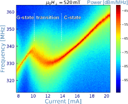
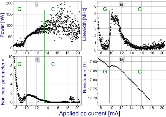
In fig. 1, we show typical measurements presenting different dynamic states: In fig. 1a, the power emission spectra of the current supplied STVO are plotted. For mA, a quasi-linear evolution of the oscillation frequency with the current is observed. As shown in fig. 1b, the oscillation parameters in this interval evolve as expected for the gyrotropic vortex motion: The linewidth decreases with the injected dc current and the oscillation amplitude increases, as also the vortex core position radius on its stable limit cycle grows with . In the following, we refer to these characteristics in the mentioned interval as the gyrotropic (G) state.
For mA, the frequency decreases rapidly with strongly enhanced linewidth (fig. 1b.ii) and nonlinearity parameterSlavin and Tiberkevich (2009); Wittrock et al. (2019) (fig. 1b.iii) compared to the low-linewidth G-state. This regime represents a transition between two frequency values, whereas the frequency at the higher current value is lower. It is generally observed and the transition can be more (see supplementary) or less (fig. 1) discrete at different values of depending on the chosen experimental parameters. Interestingly, the average sample resistance, which usually decreases monotonically with due to the TMR bias dependance, exhibits a relative increase within the transition (fig. 1b.iv) indicating a more antiparallel magnetization configuration. A third dynamical regime appears for mA, in which another quasi-linear frequency evolution with the current is observed. The linewidth FWHM stabilizes after the transition down to kHz, a similar value as obtained as well in the G-state. Importantly, the emission power is much higher than for the G-state oscillation (factor - in the presented measurement) and does furthermore not systematically change with the applied dc current. Note that however, the power is subject to rather large fluctuations at constant linewidth, potentially caused by an enhanced flicker noise in this regimeWittrock et al. (2019, 2020). For very high current values above mA, the linewidth increases again. As for the nonlinearity parameter , it first reduces almost to zero after the transition and consequently, is practically irrelevant in the measured C-state regime. However, measurements indicate that it significantly increases again for even higher currents in the C-state.

In fig. 2, we record the oscillation time signal using a heterodyne detection technique (signal down-conversion to -MHz via high-side injection and low-pass filtering) in order to resolve small variations of frequency. Note that then, one period of the heterodyne signal roughly corresponds to periods of the pure signal. At the beginning of the transition regime at mA (fig. 2.b), the oscillator is mainly in the G mode (MHz in the intervall s). In addition, for example at s, the signal shows a kink (orange arrow), which is interpreted as a part of the oscillation in the C-state or potentially pinning at the disk boundary for a short moment of time. For a short time in the interval s, the system oscillates at a slightly different frequency: We assume here, that the oscillator sometimes performs even several oscillation periods in the C-state before switching back to the G-state (see also the supplementary materialsup ). For a larger dc current mA in the center of the transition regime (fig. 2.c), the time signal is much less coherent, which we interpret as a regular switching between the states together with potential pinning events. For mA (fig. 2.d), at the end of the transition, the vortex core is again only rarely constrained at the potential barrier. For currents well above or below the transition region, and hence for the G- or C-state (fig. 2.a and 2.e, resp.), the time traces show a stable oscillation signal without observed instabilities and state switching events.
III Micromagnetic simulation
[subfigure]
\ffigbox[]{subfloatrow}[2]
\thisfloatsetupcapbesidesep=none,objectset=centering,capbesideframe=yes,capbesideposition=right,bottom
\ffigbox[\FBwidth] \thisfloatsetupcapbesidesep=none,objectset=centering,capbesideframe=yes,capbesideposition=right,bottom
\ffigbox[\FBwidth]
\thisfloatsetupcapbesidesep=none,objectset=centering,capbesideframe=yes,capbesideposition=right,bottom
\ffigbox[\FBwidth]
capbesidesep=columnsep,objectset=centering,capbesideframe=yes,capbesideposition=left,center
\fcapside[0.5]{subfloatrow}[2]
\ffigbox[\FBwidth]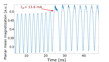
In order to further investigate the nature of the different dynamic modes, we perform mumax3 micromagnetic simulations Vansteenkiste et al. (2014) of the magnetization dynamics (see supplementarysup ). For this purpose, we include the different spin-torque contributions that can control the current driven magnetization dynamics, namely the Oersted field, Slonczewski (STT) and the field-like torque (FLT)Ralph and Stiles (2008).
Simulation results are shown in fig. 6 and reproduce the frequency characteristics of the measurements as described for the experimental data: Up to mA, we find in fig. 6 the gyrotropic mode, i.e. the quasi-circular motion of the vortex core takes place inside the nanodisk as depicted in fig. 6’s inset (see also videos in the supplementarysup ). Note that the vortex gyration is not symmetric relative to the disk center due to the FLTDussaux et al. (2012), whose efficiency compared to the STT is set to , a reasonable value for MTJ STVOsChanthbouala et al. (2011). For mA, we observe a transition to the C-state which stabilizes for higher dc currents. At this point, the introduced expression ”C-state” also becomes clear: The simulations reveal that at higher currents mA, the vortex core is not continuously found to be inside the nanodisk. Instead, it establishes that for a part of the oscillation period, the vortex core is inside and for the other part, it is imaginarily outside the disk, i.e. in the latter the in-plane magnetization of the vortex tail forms a C which precesses following an imaginary vortex core. The situation is depicted in fig. 6’s inset. Furthermore, the lower panel of fig. 6 clearly proves the vortex core oscillation radius partly inside, partly outside the nanodisk of radius . In the supplementary materialsup , movies of the occurring dynamic situations can be found. We also perform simulations without FLT, i.e. (see supplementary materialsup ). The simulation results in this case are fundamentally different and describe after the transition from the G-state a pure C-state (no renucleation of the vortex core) with significantly higher frequency in the order of GHz. These results qualitatively reproduce what has been obtained by Kawada et al.Kawada et al. (2014) for the experimental case of a GMR based STVO, where indeed the FLT is negligible. Thus, the FLT in MTJs is an important parameter in order to control the described C-state characteristics.
In the transition between the two modes in fig. 6, different situations can occur: Firstly, the system incoherently switches between both states, performing several periods in the G- and several periods in the C-state, as also observed experimentally. Secondly, the vortex core pins at the disk boundary for a certain period of time, hence stopping oscillator operation until it resumes dynamics. In fig. 6, exactly this behavior can be observed through the planar mean magnetization: For mA, the system steadily oscillates in the G-state. In this case, oscillations of the in-plane mean magnetization can be obtained because of the asymmetry in the gyrotropic motion (not centered) induced by the FLT, particularly included in the simulations. For mA, we observe a stochastic switching between the states: For example, from s, the system is in the C-state. It has a lower frequency and the planar magnetization, due to the lack of the vortex core, is slightly enhanced. From s, it can be observed that the vortex core pins at the disk boundary resulting in a quasi-constant in-plane magnetization until readopting oscillations. Comparing to experimental measurements (fig. 1), the switching between the two states translates into a broadening of the effective linewidth. Note that there, the likelihood of vortex core pinning at the boundary and thus, the range of the transition depends on several experimental parameters, such as the applied magnetic field, sample dimensionality, free layer material, etc. resulting in different characteristics of the transition (shown in the supplementarysup ). For mA in fig. 6, the system oscillates in the C-state providing coherent oscillations, although the vortex core pins at the boundary at some very short moments from time to time. The number of pinning events decreases at even higher currents. Notably, figs. 6 & 6 show that the transition region between G- and C-state is completely stochastic. The state probability can be continuously tuned within the transition until, at higher current values, the C-state is stabilized, and at lower current values, the G-state.
In fig. 6, we show the transition between G- and C-state when performing the simulation without thermal noise at K. When slightly increasing the current to the critical transition current at ns, the transition from G- to C-state oscillations is observed. Along with the reduced frequency in the C-state, also an asymmetry within one period (equally present for K) is recognized: When the vortex is expelled (high mean in-plane magnetization) for approximately half a period, the frequency is slightly reduced compared to the other half-period when the vortex core is located inside the nanodisk. Moreover, the transition between G- and C-state is discrete and both situations exhibit stable oscillations, indicating that the unstable transition region and stochastic state switching described beforehand is noise induced due to thermal fluctuations.
IV Discussion
The emission power in the C-state is considerably higher than in the G-state (fig. 1b). Comparing with the performed simulations, we attribute this to a larger active magnetic volume contributing to the magnetoresistive rf signal. The quasi-zero nonlinearity parameter in the C-state might be due to a changed confinement when the magnetization distribution is not vortex-like. Note that might again become at even higher applied current values. Moreover, the nonlinearity parameter within the transition region is rather an effective value as the system is bistable and the single-mode hypothesis does not hold any more. However, as the frequency tunability linked to the large nonlinear parameter is strongly enhanced in this regime, we anticipate that the locking ability to an external stimulus is significantly improved here. Especially interesting from an application point of view is the vicinity of a high to a regime: With the locking efficiency proportional to , the ability to respond and synchronize to an external signal could thus be easily tuned by only changing the applied dc current.
V Conclusion
In this study, we observe and describe a dynamic C-state beyond the vortex gyrotropic (G) motion in experiment and, consistently, in micromagnetic simulations. Induced by the applied dc current, the observed G- to C-state transition is found to be facilitated by the field-like torque in MTJ based STVOs and notably completely stochastic in the presence of thermal noise. The state probability can be continuously tuned within the transition regime until, at higher current values, the C-state is stabilized, and at lower current values, the G-state. We believe that the stochastic feature might be exploited for cognitive computing, for which STNOs have recently been implemented in numerous ways. Besides oscillations, stochasticity is an important feature for energy efficient neuromorphic operationsGrollier et al. (2016). The combination of both, nonlinear oscillations and stochasticity, and furthermore the ability to synchronize or respond to external stimuli, in one unique spintronic device can open the path to more multifunctional neuron-like building blocks necessary for neuromorphic computingGrollier et al. (2016).
Supplementary Material
See supplementary materialsup for details on the samples and a further experimental characterization of the occurring transition from G- to C-state. This includes the demonstration of a more discrete transition and its characterization with the applied magnetic field. Furthermore, simulation results for are shown and videos of the different regimes included.
Acknowledgments
S.W. acknowledges financial support from Labex FIRST-TF under contract number ANR-10-LABX-48-01. M.R. acknowledges support from Spanish MICINN (PGC2018-099422-A-I00) and Comunidad de Madrid (Atracción de Talento Grant No. 2018-T1/IND-11935). The work is supported by the French ANR project ”SPINNET” ANR-18-CE24-0012.
Data Availability Statement
The data that support the findings of this study are available from the corresponding author upon reasonable request.
References
- Locatelli et al. (2013) N. Locatelli, V. Cros, and J. Grollier, Nature Materials 13, 11 (2013).
- Ebels et al. (2017) U. Ebels, J. Hem, A. Purbawati, A. R. Calafora, C. Murapaka, L. Vila, K. J. Merazzo, E. Jimenez, M.-C. Cyrille, R. Ferreira, M. Kreissig, R. Ma, F. Ellinger, R. Lebrun, S. Wittrock, V. Cros, and P. Bortolotti, in 2017 Joint Conference of the European Frequency and Time Forum and IEEE International Frequency Control Symposium (EFTF/IFC) (IEEE, 2017).
- Sato et al. (2012) R. Sato, K. Kudo, T. Nagasawa, H. Suto, and K. Mizushima, IEEE Transactions on Magnetics 48, 1758 (2012).
- Choi et al. (2014) H. S. Choi, S. Y. Kang, S. J. Cho, I.-Y. Oh, M. Shin, H. Park, C. Jang, B.-C. Min, S.-I. Kim, S.-Y. Park, and C. S. Park, Scientific Reports 4 (2014), 10.1038/srep05486.
- Ruiz-Calaforra et al. (2017) A. Ruiz-Calaforra, A. Purbawati, T. Brächer, J. Hem, C. Murapaka, E. Jiménez, D. Mauri, A. Zeltser, J. A. Katine, M.-C. Cyrille, L. D. Buda-Prejbeanu, and U. Ebels, Applied Physics Letters 111, 082401 (2017).
- Kreißig et al. (2017) M. Kreißig, S. Wittrock, F. Protze, R. Lebrun, K. J. Merazzo, M.-C. Cyrille, R. Ferreira, P. Bortolotti, U. Ebels, V. Cros, and F. Ellinger, in 2017 IEEE 60th International Midwest Symposium on Circuits and Systems (MWSCAS) (IEEE, 2017).
- (7) A. Litvinenko, P. Sethi, C. Murapaka, A. Jenkins, V. Cros, P. Bortolotti, R. Ferreria, B. Dieny, and U. Ebels, 1905.02443v1 .
- Fang et al. (2019) B. Fang, M. Carpentieri, S. Louis, V. Tiberkevich, A. Slavin, I. N. Krivorotov, R. Tomasello, A. Giordano, H. Jiang, J. Cai, Y. Fan, Z. Zhang, B. Zhang, J. A. Katine, K. L. Wang, P. K. Amiri, G. Finocchio, and Z. Zeng, Physical Review Applied 11 (2019), 10.1103/physrevapplied.11.014022.
- Jenkins et al. (2016) A. S. Jenkins, R. Lebrun, E. Grimaldi, S. Tsunegi, P. Bortolotti, H. Kubota, K. Yakushiji, A. Fukushima, G. de Loubens, O. Klein, S. Yuasa, and V. Cros, Nature Nanotechnology 11, 360 (2016).
- Louis et al. (2017) S. Louis, V. Tyberkevych, J. Li, I. Lisenkov, R. Khymyn, E. Bankowski, T. Meitzler, I. Krivorotov, and A. Slavin, IEEE Transactions on Magnetics 53, 1 (2017).
- Torrejon et al. (2017) J. Torrejon, M. Riou, F. A. Araujo, S. Tsunegi, G. Khalsa, D. Querlioz, P. Bortolotti, V. Cros, K. Yakushiji, A. Fukushima, H. Kubota, S. Yuasa, M. D. Stiles, and J. Grollier, Nature 547, 428 (2017).
- Romera et al. (2018) M. Romera, P. Talatchian, S. Tsunegi, F. Abreu Araujo, V. Cros, P. Bortolotti, J. Trastoy, K. Yakushiji, A. Fukushima, H. Kubota, S. Yuasa, M. Ernoult, D. Vodenicarevic, T. Hirtzlin, N. Locatelli, D. Querlioz, and J. Grollier, Nature (2018), 10.1038/s41586-018-0632-y.
- Pribiag et al. (2007) V. S. Pribiag, I. N. Krivorotov, G. D. Fuchs, P. M. Braganca, O. Ozatay, J. C. Sankey, D. C. Ralph, and R. A. Buhrman, Nature Physics 3, 498 (2007).
- Dussaux et al. (2010) A. Dussaux, B. Georges, J. Grollier, V. Cros, A. Khvalkovskiy, A. Fukushima, M. Konoto, H. Kubota, K. Yakushiji, S. Yuasa, K. Zvezdin, K. Ando, and A. Fert, Nature Communications 1, 1 (2010).
- Novosad et al. (2002) V. Novosad, K. Y. Guslienko, H. Shima, Y. Otani, S. G. Kim, K. Fukamichi, N. Kikuchi, O. Kitakami, and Y. Shimada, Physical Review B 65 (2002), 10.1103/physrevb.65.060402.
- Guslienko et al. (2005) K. Y. Guslienko, W. Scholz, R. W. Chantrell, and V. Novosad, Physical Review B 71 (2005), 10.1103/physrevb.71.144407.
- Ivanov and Zaspel (2005) B. Ivanov and C. Zaspel, Physical Review Letters 94 (2005), 10.1103/physrevlett.94.027205.
- Taurel et al. (2016) B. Taurel, T. Valet, V. V. Naletov, N. Vukadinovic, G. de Loubens, and O. Klein, Physical Review B 93 (2016), 10.1103/physrevb.93.184427.
- Thiele (1973) A. A. Thiele, Phys. Rev. Lett. 30, 230 (1973).
- Strachan et al. (2008) J. P. Strachan, V. Chembrolu, Y. Acremann, X. W. Yu, A. A. Tulapurkar, T. Tyliszczak, J. A. Katine, M. J. Carey, M. R. Scheinfein, H. C. Siegmann, and J. Stöhr, Physical Review Letters 100 (2008), 10.1103/physrevlett.100.247201.
- Jin et al. (2009) W. Jin, H. He, Y. Chen, and Y. Liu, Journal of Applied Physics 105, 013906 (2009).
- Aranda et al. (2010) G. R. Aranda, J. M. Gonzalez, J. J. del Val, and K. Y. Guslienko, Journal of Applied Physics 108, 123914 (2010).
- Kawada et al. (2014) Y. Kawada, H. Naganuma, A. S. Demiray, M. Oogane, and Y. Ando, Applied Physics Letters 105, 052407 (2014).
- Jenkins et al. (2019) A. S. Jenkins, L. S. E. Alvarez, P. P. Freitas, and R. Ferreira, Scientific Reports 9 (2019), 10.1038/s41598-019-52236-z.
- (25) See Supplemental Material at http://address_by_publisher.com for a) details on the samples. b) a further experimental characterization of the two states. c) details on the simulations and simulation results for .
- Slavin and Tiberkevich (2009) A. Slavin and V. Tiberkevich, IEEE Transactions on Magnetics 45, 1875 (2009).
- Wittrock et al. (2019) S. Wittrock, S. Tsunegi, K. Yakushiji, A. Fukushima, H. Kubota, P. Bortolotti, U. Ebels, S. Yuasa, G. Cibiel, S. Galliou, E. Rubiola, and V. Cros, Physical Review B 99 (2019), 10.1103/physrevb.99.235135.
- Wittrock et al. (2020) S. Wittrock, P. Talatchian, S. Tsunegi, D. Crété, K. Yakushiji, P. Bortolotti, U. Ebels, A. Fukushima, H. Kubota, S. Yuasa, J. Grollier, G. Cibiel, S. Galliou, E. Rubiola, and V. Cros, Scientific Reports 10 (2020), 10.1038/s41598-020-70076-0.
- Vansteenkiste et al. (2014) A. Vansteenkiste, J. Leliaert, M. Dvornik, M. Helsen, F. Garcia-Sanchez, and B. Van Waeyenberge, AIP Advances 4, 107133 (2014), http://dx.doi.org/10.1063/1.4899186.
- Ralph and Stiles (2008) D. C. Ralph and M. D. Stiles, Journal of Magnetism and Magnetic Materials 320, 1190 (2008).
- Dussaux et al. (2012) A. Dussaux, A. V. Khvalkovskiy, P. Bortolotti, J. Grollier, V. Cros, and A. Fert, Physical Review B 86 (2012), 10.1103/physrevb.86.014402.
- Chanthbouala et al. (2011) A. Chanthbouala, R. Matsumoto, J. Grollier, V. Cros, A. Anane, A. Fert, A. V. Khvalkovskiy, K. A. Zvezdin, K. Nishimura, Y. Nagamine, H. Maehara, K. Tsunekawa, A. Fukushima, and S. Yuasa, Nature Physics 7, 626 (2011).
- Grollier et al. (2016) J. Grollier, D. Querlioz, and M. D. Stiles, Proceedings of the IEEE 104, 2024 (2016).