Millimeter-wave Multi-mode Circular Antenna Array
for Uni-cast Multi-cast and OAM Communication
Abstract
This paper investigates multi-mode and orbital angular momentum (OAM) mode data transmission techniques by a using a circular antenna array, operating at 28 GHz. The classical mode excitation of the latter is modified such that in the horizontal plane the antenna array operates as multimode transmitter (i.e., it provides broad- , uni- and/or multi-cast transmission), while in the vertical direction OAM transmission occurs: this dual-functionality by a single antenna-array at 28 GHz is presented for the first time. Specifically, it can transmit/receive in either broad-, uni-, multi-cast mode in the horizontal plane and also, it is capable of generating up to 15 spatially orthogonal OAM modes in the vertical direction. The proposed circular array is designed using twelve, low-complexity, multi-layer microstrip patch antennas with high radiation efficiency. It was tested through full electromagnetic analysis in terms of impedance matching, mutual coupling and radiation pattern. It was, also, fabricated and measured: good agreement between simulated and measurement results was observed. The proposed antenna array is perfect candidate for high spectral efficiency data transmission for 5G and beyond wireless applications.
Introduction
The development of wireless multimedia communication techniques over the last years requires the design of new, high-directive [1], compact [2], reconfigurable [3], multiple-input-multiple-output (MIMO) [4] and meta-surface antenna systems [5]. At the same time, due to congestion in the radio frequency spectrum below GHz, fifth generation of wireless communication (5G) is now exploring the best possible options at the millimeter-wave (mmWave) spectrum. From the wealth of literature on communication system hardware used for the sub- GHz G, G and earlier generations of cellular communication, Global System for Mobile Communications (GSM), Long Term Evolution (LTE) and wireless fidelity (Wi-Fi), we can easily envision that the most valuable resource in the future will be the efficient use of the spectrum. New disruptive technologies are currently being explored in the communication system community to preserve the spectrum as much as possible. Multimode circular array and Orbital Angular Momentum (OAM) transmitters are a few such technologies. Compared to standard radio, the mode–based circular array radiation is promising in terms of spectrum efficiency [6], since it can be used for orthogonal data transmission by utilizing, at the same time, spatial and frequency resources.
Wireless channel is inherently a broadcast medium, while uni– and multi–cast radio employ that a conventional spatial channel is converted to beam-space channel [7, 8]. Typically, the multi–cast technique is employed by routing at the network layer. Uni– and multi–cast techniques at physical layer means that the array equipped at the base–station (BS) or access point is creating suitable beam-patterns to serve single or multiple user groups simultaneously using same bandwidth. By doing this significant benefits in terms of spectral efficiency and reduced latency can be achieved. Beam-pattern shaping also means high directivity transmission of radio signal in prescribed directions, which in turn enhances the signal–to–noise–ratio (SNR) at the receiver end [9, 10], increasing the overall communication system efficiency and throughout. Since the channel state information is only accessible at the physical layer, uni– and multi–cast transmission at the physical layer is a complementary technique to the network-layer multi–cast routing, resulting in enhanced quality of the wireless communication system.
Several studies have investigated novel OAM mode radiation approaches which use the same time and frequency resources for the data transmission, while the radiation mechanism of OAM is different compared to multi–cast radiation. Some examples of OAM radios are based on reflector-array [11] metasurfaces [12, 13], microstrip patch antenna [13, 14], helical antenna arrays [15], and ceramic antenna arrays [16]. Generally, a multimode array is connected to a feed network which is responsible of generating the magnitude and phase of the antenna feeds required to generate spatially orthogonal modes [17]. OAM wave-fronts can be generated without the requirement of feed networks by specialized antenna geometries like in [16]. Multi–mode feed networks generally contain multiple phase shifters, switches, attenuators or radio frequency (RF) electronic devices that can control the magnitude and phase of the antenna feeding signal. For simpler cases of mode transmission, standard phase delay transmission lines are enough to realize the required antenna feed sequence. Reconfigurability is also included in some of these feed networks so that more sophisticated radio modes can be handled by the transmitter [13]. Complex feed structures like the Rotman lens are also shown to be useful for OAM multimode feed networks [18, 19, 20].
The contributions of this work is two-fold. First, we present a high efficiency –element circular array operating at GHz, capable of broadcast, uni–cast and multi–cast radio transmission along the entire deg. azimuth plane. Secondly, we show that the same circular array is capable of generating as many as spatially orthogonal OAM modes in the vertical direction: this dual-functionality by a single antenna-array at GHz is presented for the first time in the literature. The antenna array was tested through full electromagnetic analysis and measurements in terms of reflection coefficients, mutual coupling between the array elements and radiation pattern (near– and far–field). Particularly, Section II of the paper presents the synthesis technique and results of the circular array, section III discusses the uni– or multi–cast capabilities, section IV presents the spatially orthogonal OAM mode generation, while the study is concluded in section V of the paper. For the rest of the paper, circular array modes [21] along azimuth plane are represented by while the OAM modes along the elevation direction are represented by .
Results and Discussion
Twofold Function Circular Antenna Array
In this section the proposed antenna will be theoretically analysed and designed though full-electromagnetic analysis. All results will be cross-check through measurements.
Theoretical Analysis
The radiation patterns of a circular antenna array with equally spaced elements and radius of , which is placed in the horizontal plane and specifically it centre lies at the origin of coordinates, is given in the classical array literature [22, 23],
| (1) |
where,
| (2) |
is the inter–element phase–shift, is the polar, azimuthal angle respectively, is the wavenumber and is the wavelength at the operating frequency, is the single antenna element’s radiation pattern, which is usually assumed that , indicating isotropic elements, and
| (3) |
is the vector related to the th mode, which represents the current excitation on each element, where,
| (4) |
assuming that is even number, without loss of generality. Thus, for an antenna array with elements it is possible to excite modes. In order to steer the beam to a specific direction along the horizontal plane, an extra angle, , can be utilized as follows:
| (5) |
Specifically, beam rotates clockwise by angle .
In general, the circular array mode zero () gives an omnidirectional radiation pattern (broadcast), albeit with low directivity. The sum of all the modes results in a directional radiation pattern, with one main lobe (uni–cast), but now with higher directivity. Multi–mode circular antenna array also allows multi–cast transmission: by summing all the modes expect zero mode, the final radiation pattern includes multiple lobes, and thus, antenna can transmit to different directions.

Circular Patch Antenna Array Design
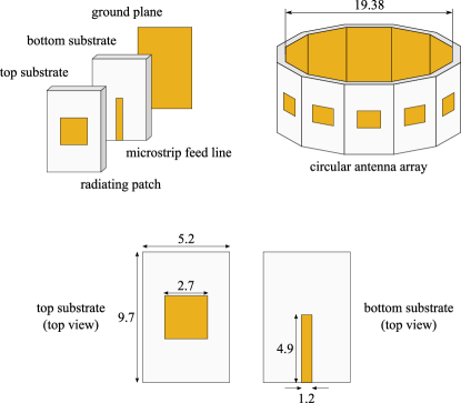
To realize the circular array, we use an electromagnetically coupled patch antenna designed using two substrate layers. The bottom layer is designed on Rogers RO4003 substrate (, ) while the top layer is designed on Taconic TLY–5A substrate (, ). The antenna element is fed by a micro-strip transmission line [24], designed on Taconic TLY–5A with full ground plane. The microstrip line is fed by a lumped port when the antenna is simulated in full wave electromagnetic simulation tool CST Microwave Studio. The patch antenna geometry and optimized design parameters are presented in Fig. 1 when the antenna is placed in –plane. Here, it can be observed that the microstrip patch is fed at the centre such that the patch radiation is isolated from the feed line and there is a gap between the feeding mechanism and radiating patch. This allows high directivity radiation along the – as well as –directions with realized gain of dBi and consistent half–power beam width of deg. and deg. along - and -planes. The benefit of this antenna radiation mechanism will be shown in the later section when same antenna will be used for multi-cast and OAM mode radiation in different directions. The antenna is matched to operate at GHz with simulated radiation efficiency.
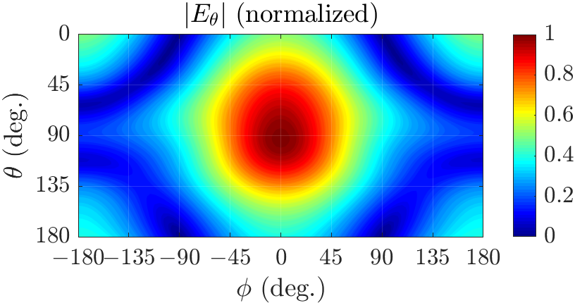
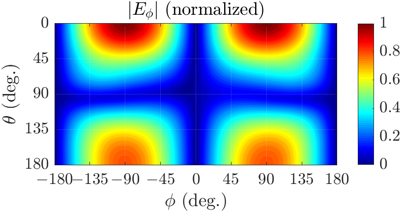
We can see from Fig. 2a and 2b that in the horizontal plane ( deg.) the maximum -field occurs for = 0 deg. At this plane, is equal to the component , which is vertical to the horizontal plane, while component is zero. On the other hand, is maximized at deg., i.e., at the top of the antenna, and for deg., where vanishes. Actually, where is maximized is minimized and vice-versa. Thus, in the horizontal plane, the dominant electric component in the far-field is the , which is perpendicular to the horizontal plane and leads to the multimodal function, while in the vertical direction, on the top of the antenna, the dominant electric component in the far-field is the , which is parallel to the horizontal plane and leads to the OAM function.
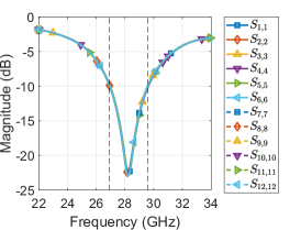
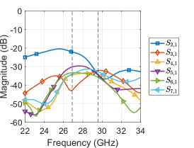
Copies of the patch antennas are placed in a circular array formation same as in Fig. 1 in (horizontal) –plane when the array diameter mm (). Simulated –parameters of the circular array is shown in Fig. 3, when all other antenna ports are terminated to matched load to test simultaneous array excitation. Reflection coefficient results (Fig. 3a) show each antenna operates from to GHz (9.5 bandwidth) with a return loss lower than dB. Due to cylindrical symmetry of the array based on (1), cross coupling results against excitation of only ports are shown in Fig. 3b. The worst cross coupling is between immediate neighbouring elements ( dB at GHz) while it is below this value for the rest of the cases.
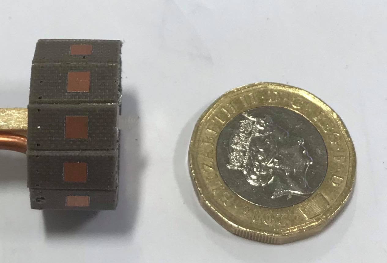
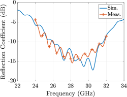
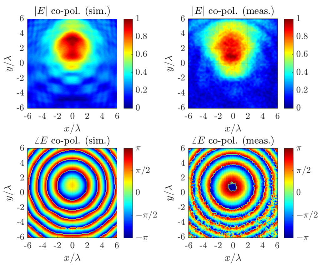
The array is realized using a combination of separately fabricated patch antennas, each connected to a coaxial feed line as shown in Fig. 4a. The array antenna matching is measured by first connecting single antenna coaxial feed to a Vector Network Analyser while all other antenna ports are kept open. The return loss is shown in Fig. 4b. After confirmation of good matching, the antenna array is placed in a planar near–field measurement facility and magnitude and phase responses are recorded along the –direction. Measurements were taken using vertically and horizontally polarized measurement probe when circular array is placed in the near field of the 28 GHz probe. Results shown in 4c and 4d verifies the simulated predictions; a clear correlation between measured and simulated fields can be observed from the magnitude and phase plots for both co– and cross–polarization fields. After successful verification of the circular array operation same array is used to generate multi–cast and OAM modes that are discussed in the proceeding sections.
Uni– and Multi–cast Transmission
The mode-mixing excitation of a circular array allows uni-cast and multi-cast radio transmission in addition to broadcast, and this is done by using only some of the modes from (4). In this section, we show that the patch antenna circular array can generate two uni–cast and three multi–cast radio transmissions. Two cases of uni-cast A and B are shown which are resulted by the mode mixing and . Multi-cast has three cases; A, B and C. The case A is a result of mode mixing of , B is a result of mode mixing , and for C it is . The simulated results for the electric component in the far–field, estimated thought CST Microwave Studio is depicted in Fig. 5. First, the broadcast radiation pattern () in the horizontal plane, where all the elements are exited by the same signal and the phase difference between them is zero, is depicted in Fig. 5a: the electric field is omni–directional, as expected in that case, with a maximum of dBV/m and corresponding directivity of dBi: it is noted that the maximum directivity in that case is dBi but occurs in the plane deg. and not in the horizontal plane (i.e., deg.) Electric field for the uni–cast modes A and B is depicted in Fig. 5b and 5c and has maxima of and dBV/m, respectively, with corresponding directivity of and dBi. For the multi–cast cases, simulated results are shown in Fig. 5d–5f, where the circular array is capable of data transmission in three dominant directions, i.e., deg., deg. Here the corresponding peak directivity at deg. decreases from dBi (multi–cast case A) to dBi (case B) to dBi (case C) at an expense of the radiated power from the array in multiple directions being equalized. This is evident from Fig. 5f where almost equal power is radiated along three directions.
Broadcast and all scenarios of uni–cast and multi–cast are cross-verified with the measurements taken in anechoic environment. The circular array is placed in a turn table of the far-field anechoic chamber, as will be explained in Measurements section, and its radiated electric field in the horizontal plane is measured along deg. through a receiver horn antenna [25] operating at GHz and also depicted in Fig. 5 for comparison. Only a singe antenna element of the circular antenna array is fed and the total depicted measured radiation patterns are then mathematical estimated based on basic antenna array theory [23]: the total field is the superposition of the single element’s pattern because of the antenna array’s cylindrical symmetry. Good agreement between simulated, measured results is observed.
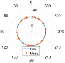
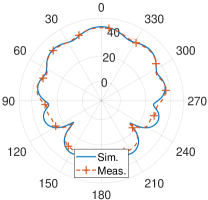
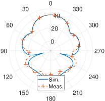
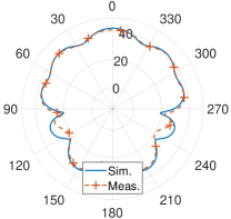
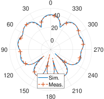
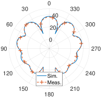
These results are considered as reference to compare the performance of uni– and multi–cast transmission. Uni–cast case B seems to be the highest directivity transmission option, whilst multi–cast case B and C can be good choices when simultaneous data transmission is desirable along three directions around the circular array.
Also, please note that, all the beams for the uni– and multi–cast transmission (Fig. 5)) can be rotated by angle , based on (5), and thus, the proposed, multi-mode antenna is steerable, providing deg. rotation in the horizontal plane. In order to dynamically change the current’s phase on each antenna element, various practical techniques can be applied, e.g., Rotman Lens and phase ramps [18, 19, 20].
OAM Mode Transmission
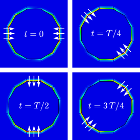
Advantageously, the same circular antenna array in Fig. 1 and 4a can generate up to OAM modes along –direction (i.e., deg.) when the array is placed in the reference horizontal plane (–plane). The generation of OAM modes is a consequence of radiation characteristics of the single antenna element, as previously described. Based on Fig. 2 it is evident that the antenna is capable of transmitting in both ways, well separated from each other. Specifically, in the horizontal plane the dominant electric component is the , resulting vertical polarization, and thus, multimodal operation, whilst, in the vertical direction the dominant component is the , which in tern, is coupled with resulting radiated field of the other elements of the array, leading to OAM operation. Putting this statement into perspective, note the gap between feeding line on Rogers RO4003 substrate and radiating patch on Taconic TLY-5A substrate in Fig. 1. When the radiating patches are placed in circular array formation, and if we observe the array from the top, we can observe a series of radiating copper edges tangential to the array circle (Fig. 6). These edges act as resonant slots and is primarily responsible for majority of the OAM modes. Mathematically, the excitation vector for the element circular array is given by
| (6) |
where, represents the antenna elements of the array and is the OAM mode number. The number of the antenna elements in the circular array determines the number of the OAM modes that can be produced [26]. The radiation mechanism, which leads to OAM transmission is presented in Fig. 6. Specifically, it is depicted the simulated surface current distribution of the antenna array at different time phases ( is the period) for the first mode (). As the period increases by deg., the current phase is shifting accordingly. Also, the current vectors have opposite direction, as described in [26] for the same mode (), which leads to OAM transmission.
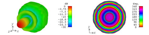
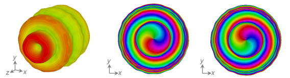
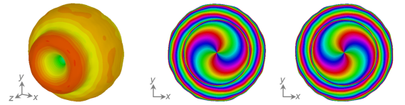
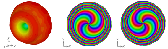
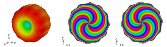
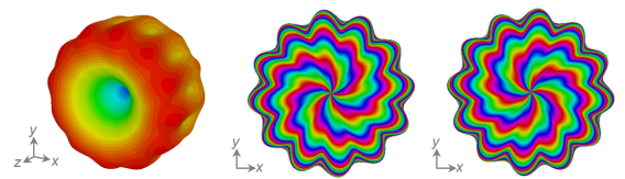
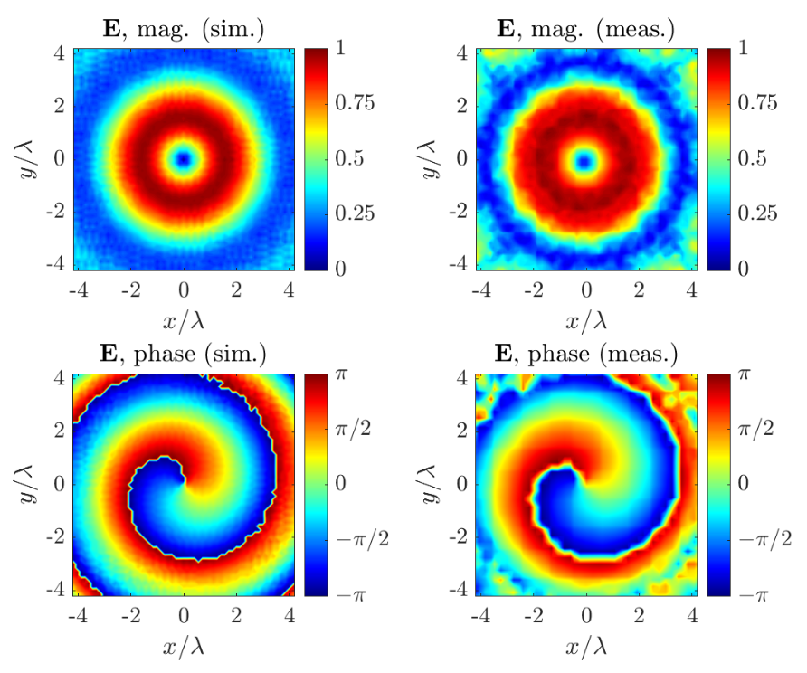
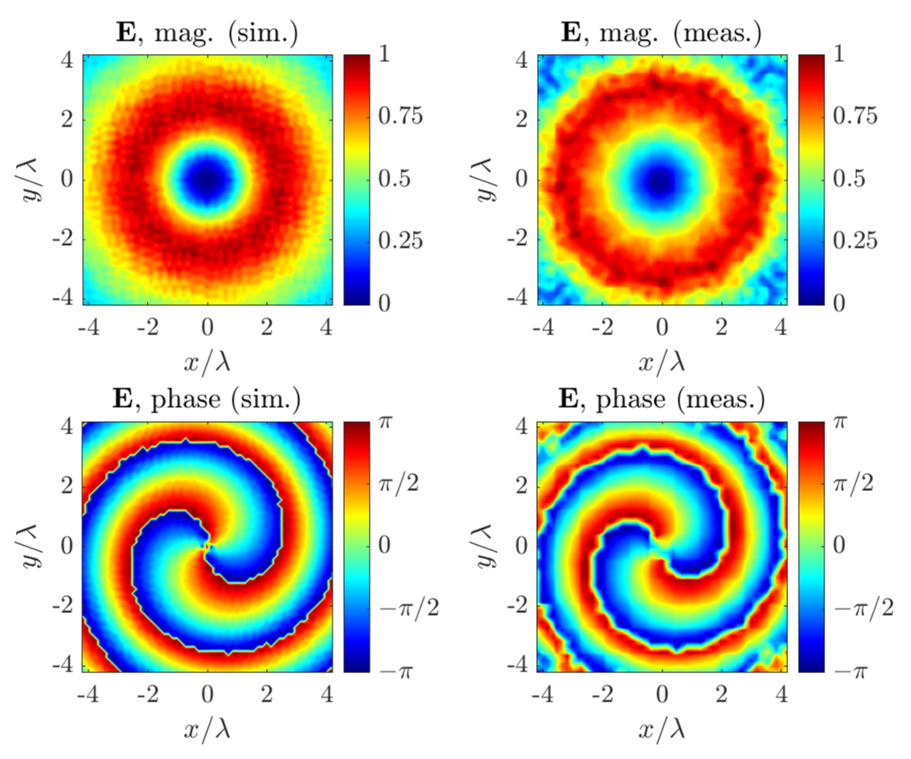
Fig. 7 depicts the simulated results. Excitation of mode (Fig. 7a) reveals a directional radiation pattern with constant phase value around the -direction. When modes and are excited (Fig. 7b and 7c, respectively), vortices are revealed along the -direction, while single and double cycles of phase spiral ( deg.– deg.) are observed in the radiation pattern phase. The phase spiral is clockwise for while it is counter-clockwise for . Note that the phase response for a given -th modes is responsible for spatial orthogonality, hence simultaneous data transmission using OAM modes is possible, as verified by literature [6, 12, 13, 11, 16, 14, 15, 17, 18]. The far-field response against the remaining out of mode excitations is shown in Fig. 7d to 7f. Other than the excitation of mode (Fig. 7a), all other mode excitations create vortices along -direction. The number of deg.– deg. clockwise and anti-clockwise phase spirals increases as we move higher in the mode number (i.e. ), and this trend breaks for the highest OAM modes i.e. . Another interesting feature to observe is that the radiation pattern magnitude for mode excitation and reveal quasi-broadcast transmission along -plane in addition to the OAM modes in -direction, which provides an additional flexibility in terms of application scenarios to the presented circular array.
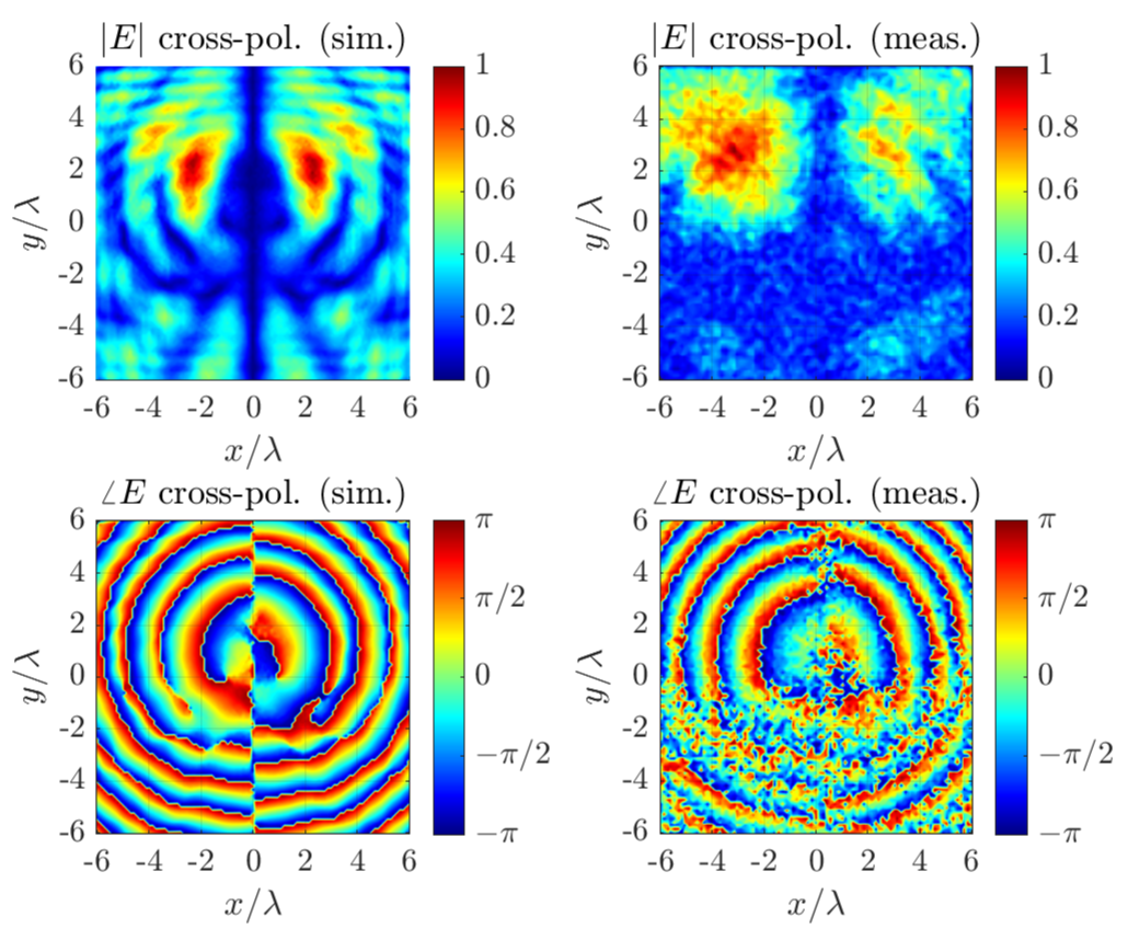
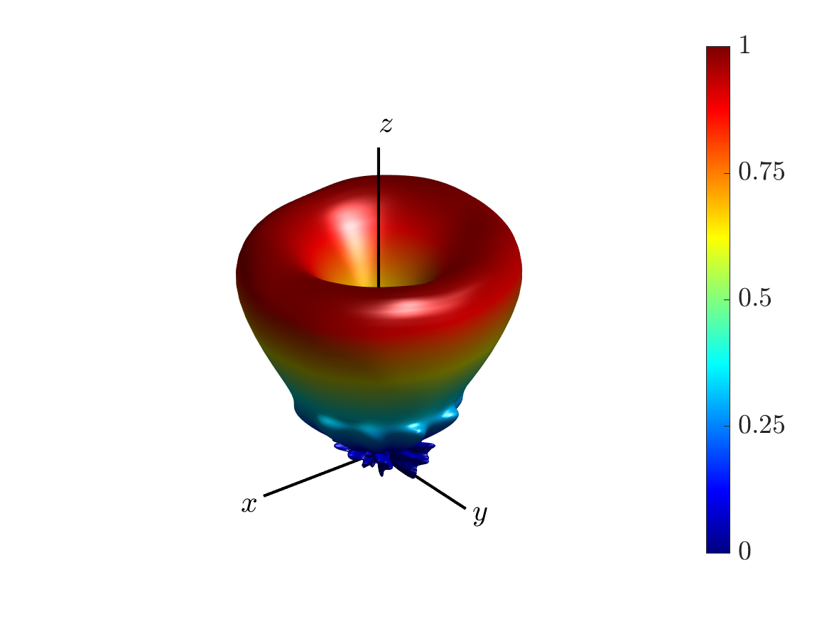
Two of the OAM modes () are verified by measurements in planar near-field anechoic chamber. The circular array is placed in near-field of a GHz scanning probe such that the probe is facing the -direction of the circular array placed in -plane. Electric field is recorded, normalized to the maximum field value, and is compared to the predictions from CST Microwave Studio simulations. The results are presented in Fig. 8. For healthy comparison, the phase spiral for simulation is rotated in a post-processing step to match with the phase spiral recorded from measured data. Plots against excitation in Fig. 8a show that the phase spiral is matched well with the simulated predictions while the magnitude is flattened around the vortex in -direction. In the same way, phase spiral matches well with the simulated results for excitation. All the above measured results verify the OAM function of the antenna array in the vertical direction. Finally, the far-field radiation pattern is estimated from the near field measurement results, through the near to far–field transformation, based on the asymptotic evaluation method, described in [27], and the results (3D representation of the normalized magnitude in spherical coordinates) is depicted in Fig. 9.
Methods
Simulation setup
The antenna was simulated in terms of reflection coefficient, cross coupling and radiation pattern through full electromagnetic analysis by using the commercial numerical solver CST Microwave Studio suite. Specifically, the frequency domain solver (finite element method (FEM)) was used. Discrete ports at ohm were applied as excitation. In order to estimated the radiation pattern for each mode, for the uni– and multi–cast and for the OAM transmission, the schematic representation of the antenna and the AC, combine result simulation task tool was used.
Measurement setup
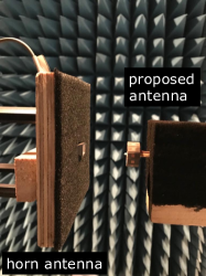
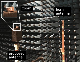
The measurement setup for the near– and far–field is depicted in Fig. 10, respectively. For the near–field measurements the proposed antenna was placed at vertical distance of from a receiver horn antenna. The latter scanned a planar region with dimensions and captured the transmitted by the proposed antenna electric field. The region was divided into measurement points. For the cross–polarized component measurement the horn antenna was rotated by deg. For the far-field measurement, the receiver horn antenna is placed at distance. Both antennas lie in the horizontal plane. Now, the proposed antenna rotates degrees around its axis and the horn antenna captures the transmitted signal.
Conclusion
This work presents a circular patch antenna array capable of generating uni- and multi-cast transmission along azimuth plane and, simultaneously, a high number of OAM modes in elevation direction. The mode-based analysis is thoroughly investigated through fundamental principles and it is shown that mode-mixing of circular antenna array can result in various uni-cast and multi-cast transmissions. OAM mode excitations can result in several OAM modes transmission, where most of the latter show high level of spatial orthogonality. Antenna was fabricated via a conventional milling machine and tested in terms of reflection coefficient, near- and far-field radiation patter. Simulated results through full electromagnetic analysis and measured results agree very well in all cases. The array is perfect candidate for high spectral efficiency data transmission for 5G and beyond wireless applications.
Acknowledgment
This research was supported in part by the UK Engineering and Physical Sciences Research Council (EPSRC) under the UKRI grants EP/P000673/1 and EP/NO20391/1. Authors would like to thank K. Rainey and O. Malyuskin for assisting in the hardware development and measurements.
Author Contributions
S.D.A. and V.F. conceived the idea. S.D.A. designed and simulated the proposed antenna, performed the measurements, interpreted results and edit the paper. M.A.B.B wrote the paper. S.D.A. and V.F. supervised the research and contributed to the general concept and interpretation of the results. All authors reviewed the manuscript.
References
- [1] S. D. Assimonis, T. Samaras, and V. Fusco, “Analysis of the microstrip-grid array antenna and proposal of a new high-gain, low-complexity and planar long-range wifi antenna,” IET Microwaves, Antennas Propagation, vol. 12, no. 3, pp. 332–338, 2018.
- [2] S. D. Assimonis, V. Fusco, A. Georgiadis, and T. Samaras, “Efficient and sensitive electrically small rectenna for ultra-low power rf energy harvesting,” Scientific Reports, vol. 8, no. 1, p. 15038, 2018.
- [3] S. D. Assimonis, A. Theopoulos, and T. Samaras, “A new high-gain and low-complexity pattern-reconfigurable antenna,” in 2015 9th European Conference on Antennas and Propagation (EuCAP), 2015, pp. 1–4.
- [4] W. Tan, S. D. Assimonis, M. Matthaiou, Y. Han, X. Li, and S. Jin, “Analysis of different planar antenna arrays for mmwave massive mimo systems,” in 2017 IEEE 85th Vehicular Technology Conference (VTC Spring), 2017, pp. 1–5.
- [5] O. Yurduseven, S. D. Assimonis, and M. Matthaiou, “Intelligent reflecting surfaces with spatial modulation: An electromagnetic perspective,” ArXiv, vol. 2006.12643, 2020.
- [6] M. L. Chen, L. J. Jiang, and W. E. Sha, “Orbital angular momentum generation and detection by geometric-phase based metasurfaces,” Applied Sciences, vol. 8, no. 3, p. 362, 2018.
- [7] W. Hao, G. Sun, Z. Chu, P. Xiao, Z. Zhu, S. Yang, and R. Tafazolli, “Beamforming design in swipt-based joint multicast-unicast mmwave massive mimo with lens-antenna array,” IEEE Wireless Communications Letters, vol. 8, no. 4, pp. 1124–1128, 2019.
- [8] X. Zhang, S. Sun, F. Qi, R. Bo, R. Q. Hu, and Y. Qian, “Massive mimo based hybrid unicast/multicast services for 5g,” in 2016 IEEE Global Communications Conference (GLOBECOM), 2016, pp. 1–6.
- [9] E. Karipidis, N. D. Sidiropoulos, and Z. Luo, “Far-field multicast beamforming for uniform linear antenna arrays,” IEEE Transactions on Signal Processing, vol. 55, no. 10, pp. 4916–4927, 2007.
- [10] X. Xu, B. Du, and C. Wang, “On the bottleneck users for multiple-antenna physical-layer multicasting,” IEEE Transactions on Vehicular Technology, vol. 63, no. 6, pp. 2977–2982, 2014.
- [11] H. Huang and S. Li, “High-efficiency planar reflectarray with small-size for oam generation at microwave range,” IEEE Antennas and Wireless Propagation Letters, vol. 18, no. 3, pp. 432–436, 2019.
- [12] H. Wang, Y. Li, Y. Han, Y. Fan, S. Sui, H. Chen, J. Wang, Q. Cheng, T. Cui, and S. Qu, “Vortex beam generated by circular-polarized metasurface reflector antenna,” Journal of Physics D: Applied Physics, vol. 52, no. 25, p. 255306, apr 2019.
- [13] J. Wu, Z. Zhang, X. Ren, Z. Huang, and X. Wu, “A broadband electronically mode-reconfigurable orbital angular momentum metasurface antenna,” IEEE Antennas and Wireless Propagation Letters, vol. 18, no. 7, pp. 1482–1486, 2019.
- [14] C. Guo, X. Zhao, C. Zhu, P. Xu, and Y. Zhang, “An oam patch antenna design and its array for higher order oam mode generation,” IEEE Antennas and Wireless Propagation Letters, vol. 18, no. 5, pp. 816–820, 2019.
- [15] F. Shen, J. Mu, K. Guo, S. Wang, and Z. Guo, “Generation of continuously variable-mode vortex electromagnetic waves with three-dimensional helical antenna,” IEEE Antennas and Wireless Propagation Letters, vol. 18, no. 6, pp. 1091–1095, 2019.
- [16] K. Bi, J. Xu, D. Yang, Y. Hao, X. Gao, and S. Huang, “Generation of orbital angular momentum beam with circular polarization ceramic antenna array,” IEEE Photonics Journal, vol. 11, no. 2, pp. 1–8, 2019.
- [17] G. Junkin, “A circularly polarized single-frequency multimode helical beam antenna,” IEEE Transactions on Antennas and Propagation, vol. 67, no. 3, pp. 1459–1466, 2019.
- [18] X.-D. Bai, X.-L. Liang, J.-P. Li, K. Wang, J.-P. Geng, and R.-H. Jin, “Rotman lens-based circular array for generating five-mode oam radio beams,” Scientific Reports, vol. 6, no. 1, p. 27815, 2016.
- [19] M. A. B. Abbasi, V. Fusco, U. Naeem, and O. Malyuskin, “Physical layer secure communication using orbital angular momentum transmitter and a single antenna receiver,” IEEE Transactions on Antennas and Propagation, pp. 1–1, 2020.
- [20] M. A. B. Abbasi, V. F. Fusco, and U. Naeem, “Communication to a spinning cubesat using a two-mode planar circular array,” Electronics Letters, vol. 56, no. 10, pp. 519–521, 2020.
- [21] A. Chepala, Y. Ding, and V. F. Fusco, “Multimode circular antenna array for spatially encoded data transmission,” IEEE Transactions on Antennas and Propagation, vol. 67, no. 6, pp. 3863–3868, 2019.
- [22] H. L. Van Trees, Optimum array processing: Part IV of detection, estimation, and modulation theory. John Wiley & Sons, 2004.
- [23] B. Sheleg, “A matrix-fed circular array for continuous scanning,” Proceedings of the IEEE, vol. 56, no. 11, pp. 2016–2027, 1968.
- [24] K.-L. Wong, Compact and broadband microstrip antennas. John Wiley & Sons, 2004, vol. 168.
- [25] M. A. B. Abbasi, V. F. Fusco, H. Tataria, and M. Matthaiou, “Constant- lens beamformer for low-complexity millimeter-wave hybrid mimo,” IEEE Transactions on Microwave Theory and Techniques, vol. 67, no. 7, pp. 2894–2903, 2019.
- [26] B. Thidé, H. Then, J. Sjöholm, K. Palmer, J. Bergman, T. D. Carozzi, Y. N. Istomin, N. H. Ibragimov, and R. Khamitova, “Utilization of photon orbital angular momentum in the low-frequency radio domain,” Phys. Rev. Lett., vol. 99, p. 087701, Aug 2007.
- [27] C. A. Balanis, Antenna theory: analysis and design. John Wiley & Sons, 2016.