Digital Metasurface Based on Graphene: An Application to Beam Steering in Terahertz Plasmonic Antennas
Abstract
Metasurfaces, the two-dimensional counterpart of metamaterials, have caught great attention thanks to their powerful capabilities on manipulation of electromagnetic waves. Recent times have seen the emergence of a variety of metasurfaces exhibiting not only countless functionalities, but also a reconfigurable response. Additionally, digital or coding metasurfaces have revolutionized the field by describing the device as a matrix of discrete building block states, thus drawing clear parallelisms with information theory and opening new ways to model, compose, and (re)program advanced metasurfaces. This paper joins the reconfigurable and digital approaches, and presents a metasurface that leverages the tunability of graphene to perform beam steering at terahertz frequencies. A comprehensive design methodology is presented encompassing technological, unit cell design, digital metamaterial synthesis, and programmability aspects. By setting up and dynamically adjusting a phase gradient along the metasurface plane, the resulting device achieves beam steering at all practical directions. The proposed design is studied through analytical models and validated numerically, showing beam widths and steering errors well below 10o and 5% in most cases. Finally, design guidelines are extracted through a scalability analysis involving the metasurface size and number of unit cell states.
Index Terms:
Beam steering, Digital metasurfaces, Graphene, Plasmonics, Terahertz frequencies.I Introduction
Metasurfaces, defined as artificial structures with subwavelength thickness, have enabled the realization of novel compact devices with unprecedented electromagnetic control. Frequency selectivity, absorption, anomalous reflection/transmission, polarization conversion, and focusing are among the many electromagnetic functionalities that can be achieved through the careful design of the metasurfaces [1, 2]. With such unprecedented control of the response to the impinging wave, metasurfaces have led to important breakthroughs in electromagnetic cloaking, imaging, as well as in the creation of ultra-efficient, miniaturized antennas for sensors and implantable communication devices [3, 4, 5, 6, 7, 8].
A metasurface is generally defined as a planar array of periodic or quasi-periodic subwavelength elements, whose structure and coupling determine the electromagnetic function. As long as the elements remain subwavelength in size, the working principle of metasurfaces can be applied from microwaves to the visible range [2]. Between these two extremes lies the terahertz (THz) band, for which designs have been reported to manipulate the phase, amplitude or polarization of the waves reflected or transmitted by the metasurface [9, 10, 11, 12].
The main issue of conventional metasurfaces are the lack of adaptivity and reconfigurability as, in most designs, the electromagnetic function and its scope are fixed once the unit cell is designed. In order to avoid re-designing and re-fabricating metasurfaces each time a change in frequency or functionality is required, one can introduce tunable or switchable elements in the design of unit cells [13]. The resulting reconfigurable metasurfaces can be globally or locally tunable depending on the specific design, and better yet through appropriate control means, they can become programmable [14, 15].
Coding metamaterials, sometimes also referred to as digital metamaterials, are a particular type of programmable metamaterials that discretize the number of states of a unit cell [16, 17, 18, 19]. Each state is represented by a number of bits that are used to make the actual metasurface. A desired global response is achieved through a medium profile that is not necessarily periodical. Such structure, when built using locally switchable elements, can be elegantly described as a bit or state matrix and digitally controlled through reconfigurable devices such as Field-Programmable Gate Arrays (FPGAs) [19]. Several examples implementing polarization control, focusing control, or beam manipulation in the GHz range can be found in the literature [19, 20, 21].
Graphene, with its outstanding optoelectrical properties, has been recently introduced as a key enabler of a myriad of applications in countless domains [22, 23, 24, 25]. It is well known that graphene naturally supports Surface Plasmon Polaritons (SPP) in the terahertz band, and therefore, becomes an excellent option for the implementation of terahertz sources [26] and antennas [27], among others. The plasmonic nature of graphene at terahertz frequencies leads to miniaturized devices [28], whereas its inherent tunability has been leveraged in frequency-agile or reconfigurable concepts [29, 30, 31]. Some of such designs are array-based, and similar to programmable metasurfaces, they achieve reconfigurability by switching the state of its elements, i.e. tuning them in or out [32, 33, 34].
The above-mentioned properties turn graphene into a unique material for the implementation of terahertz reconfigurable metasurfaces. First explorations in this regard considered graphene reflectarrays and studied their amplitude-phase responses when tuning the chemical potential of the graphene [35]. By means of local tuning of the graphene elements through electrostatic biasing, the scattering profile of the reflectarray can be modified to achieve beam steering [36], focusing [37], diffusive scattering [38], cloaking [39] or wave vorticity control [40]. phase change materials (PCMs) [41], semiconductor diodes [42], [43]. . , the design can be greatly simplified and the device can be reconfigured much faster.
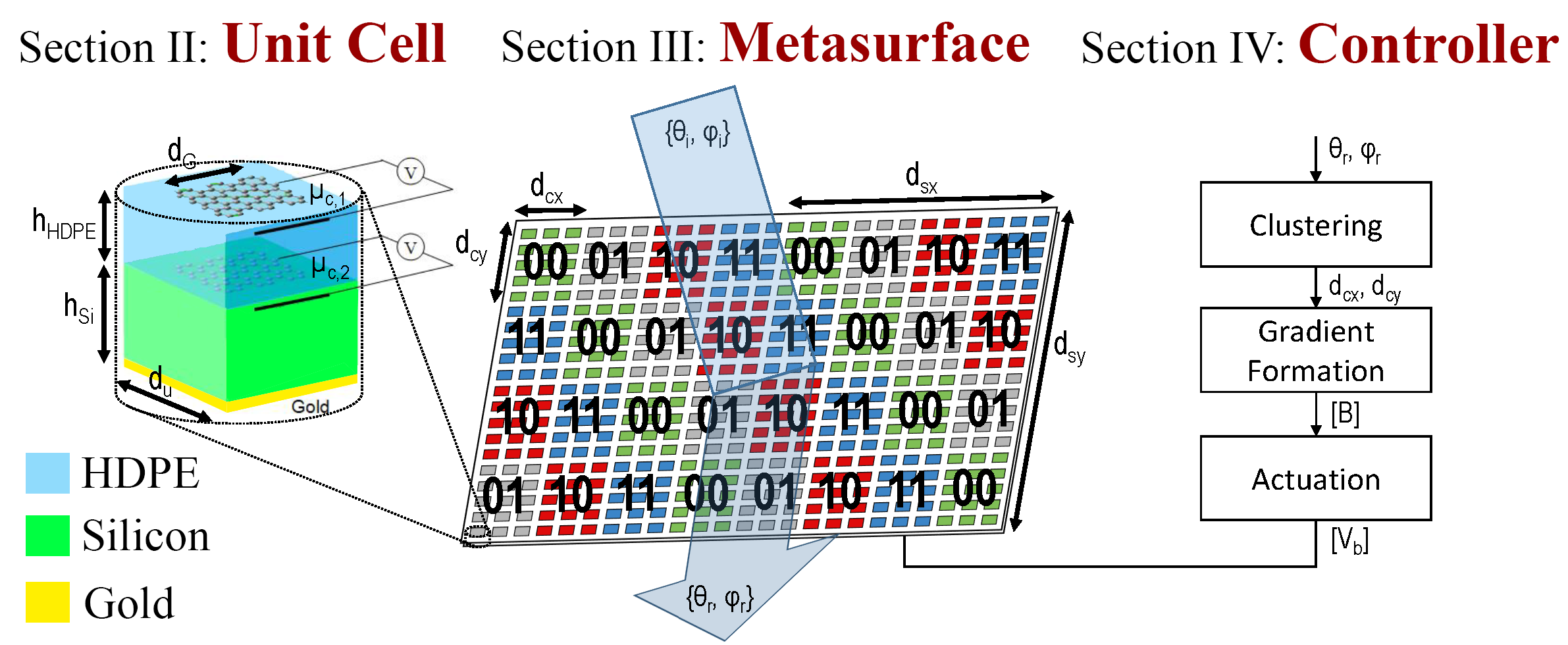
Although the natural switchability of graphene in the terahertz band matches perfectly with the coding metamaterial paradigm, which has been explored in [44] for the first time, the lack of literature to present a clear methodology for the unit cell design based on graphene and the coding of the metasurface seems evident. To bridge this gap, this paper presents a comprehensive methodology for the design of programmable metasurfaces from the unit cell to the metasurface controller (Figure 1). The proposed methodology is then applied to develop a metasurface for fine-grained beam steering at terahertz frequencies. The metasurface acts as a reflectarray that forms dynamically reconfigurable phase gradients in the X and Y directions, through which the reflected beam can be driven to any desired direction. The unit cells of the reflectarray are based on a graphene-insulator-graphene stack that achieves wide phase tuning via electrostatic biasing of the graphene patches. With two bits per unit cell and the appropriate controller, the proposed metasurface achieves a very wide steering range with low beam width.
The proposed metasurface is particularly suitable for wireless communication applications. In this context, the use of the lower part of the THz spectrum (our design operates at THz) becomes extremely attractive due to the abundance of bandwidth that allows to satisfy the extreme data rate demands of 5G networks and beyond [45]. Communication in the THz band, however, requires overcoming high path losses mainly through directive antennas with very narrow beams and through the use of smart programmable reflectors [46, 47, 48, 49, 34]. It is thus fundamental that these devices be capable of steering the THz beam with high precision to track the users and avoid interrupting communication.
In summary, the main contributions of this paper are:
-
•
The development of a comprehensive methodology for the design of graphene-based programmable terahertz metasurfaces for beam steering, from the unit cell up to the global controller.
-
•
The use of the proposed methodology to design and evaluate a 2-bit coding metasurface for beam steering. Wide steering range with a sharp reflected beam and low overheads are demonstrated. The chosen frequency of operation is THz, within the range expected for THz wireless communication applications.
-
•
A scalability analysis illustrating the relation between the different design parameters and performance metrics, and uncovering several co-design opportunities.
The rest of this paper is organized as shown schematically in Fig. 1. Section II presents a design space exploration of graphene-based unit cells from the perspectives of size, chemical potential, and number of states. Section III formulates a design flow for beam steering coding metasurfaces, which is then tested by showing the effective steering of the antenna beam in several directions. Section IV discusses and evaluates the implementation of the scheme that actually controls and (re)programs of the metasurface. Finally, Section V outlines the main scalability trends and co-design opportunities of the proposed design. Section VI concludes the paper.
II Graphene-based unit cell
The design of any metasurface starts with its most basic building block, namely, the unit cell. For beam manipulation, we need to provide a unit cell with the ability of controlling the phase response over a wide range of values [12]. Moreover, since the proposed device acts as a reflectarray, the unit cell needs to yield a high reflection amplitude at all times. To enable dynamic reconfigurability, it is necessary that both objectives can be met without physically changing any geometry. In this paper, reconfigurability is achieved at THz frequencies by means of the electrostatic tuning of graphene.
II-A Graphene Modeling
We analyze different unit cells that leverage the tunability of graphene to achieve the desired phase variation with reasonable losses and without the need of changing any geometry. To drive the design and to perform an accurate evaluation of different proposals, we model graphene as an infinitesimally thin sheet with surface impedance , where is the frequency-dependent conductivity of graphene. The complex conductivity is given by
| (1) |
where , and are constants corresponding to the charge of an electron, the reduced Planck constant and the Boltzmann constant, respectively [50]. Variables , and correspond to the temperature, the relaxation time and the chemical potential of the graphene layer. Note that this expression neglects the edge effects of the graphene and considers that the Drude-like intraband contribution dominates, which are experimentally validated assumptions at the sizes and frequencies considered in this work [51].
On the one hand, the phase control in graphene metasurface is achieved via changes in its complex conductivity when biased – the effect that can be modeled through the chemical potential value . The chemical potential can be controlled through electrostatic biasing, and therefore, we can meet the phase change requirement. On the other hand, the amplitude response depends on the losses within graphene, which are mostly influenced by the relaxation time value . Note that the relaxation time is proportional to the carrier mobility, which depends on the quality of the material. For the purpose of this work, losses will be affordable as long as the carrier mobility of the graphene sheets is on the order of 10,000 cm2V-1s-1, which is achievable with current fabrication and encapsulation techniques [52]. Thus, the amplitude requirement can be met as well.
II-B Unit Cell Design
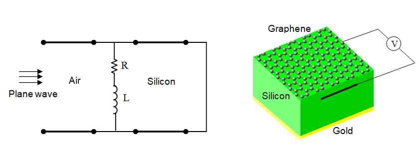
Figure 2 shows a schematic representation of the proposed unit cells together with their approximate equivalent circuit models. We numerically simulate different designs in CST Microwave Studio [53] to obtain the amplitude and phase responses. Then, through the equivalent circuit models, we verify the results of the numerical approach, and reason about the behavior of different unit cells. In all cases, we assume a lateral size of m. This value is around for the targeted frequency of operation (2 THz), enough to provide the subwavelength behavior required in the metasurface. The relaxation time of graphene is assumed to be ps, which is compatible with the carrier mobility requirements mentioned above.
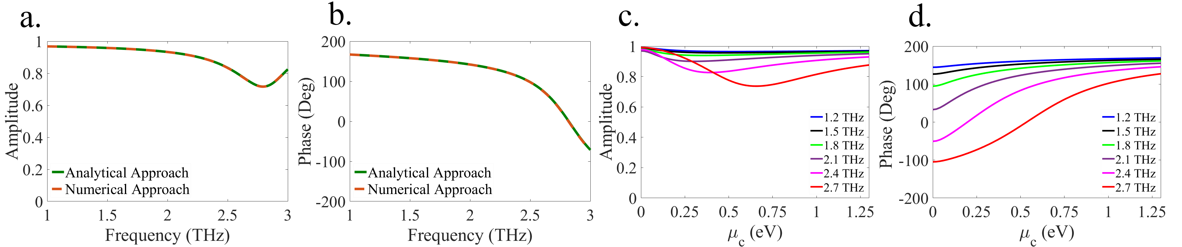
The first unit cell (Fig. 2(a)) consists of a fully covered layer of graphene on top of a silicon substrate with refractive index and thickness m along with a metallic ground plane on the backside. In such a unit cell, graphene is a lossy medium that can be modeled through an circuit. Fig. 3 plots the amplitude and phase responses of reflection coefficient for such unit cell versus frequency and the chemical potential. It is observed that the amplitude response is within an acceptable range, whereas the phase range is not wide enough –around 135o at 2 THz assuming a maximum chemical potential range of 1 eV. A very good agreement is also obtained between the numerical results and the equivalent circuit model.
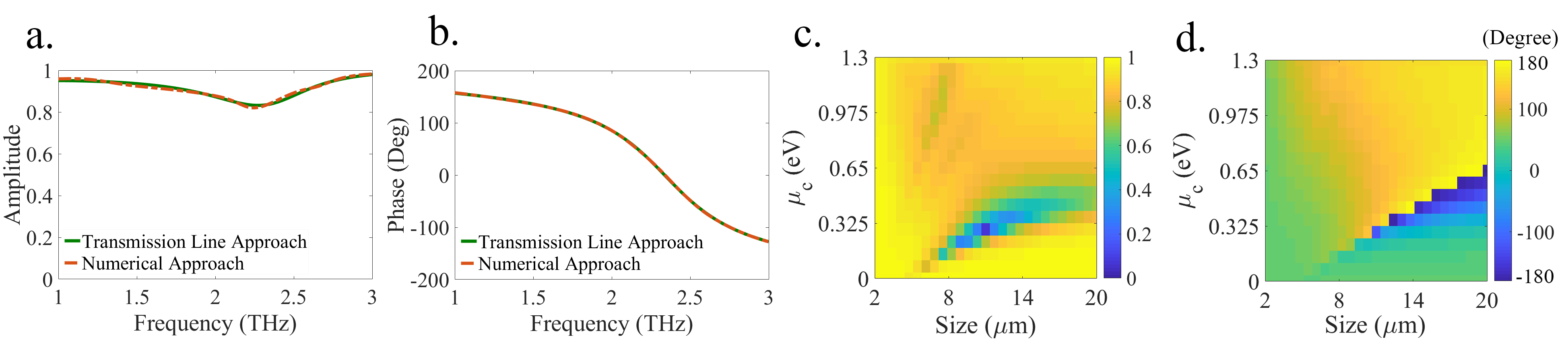
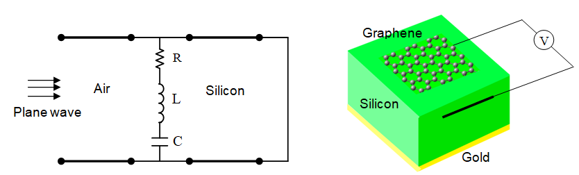
The second unit cell (Fig. 2(b)) consists of a graphene patch that partially covers the unit cell. The substrate and ground plane remain unchanged. In this case, a capacitance is introduced to model the coupling effects generated between the edges of adjacent graphene patches. As shown in Fig. 4, the size of the graphene patch provides an extra degree of freedom to deliver the target amplitude and phase responses. Exploring the {chemical potential, patch size} design space, we observe that there is a tradeoff between the amplitude and phase variation. For a patch size of 6 m, the phase range covers almost 360o with less than 0.8 eV chemical potential variation. However, the amplitude response also has a very large variation, which discourages the choice of such design point. A patch size of 8 m or larger provides a better amplitude response with a reasonable phase change variation.
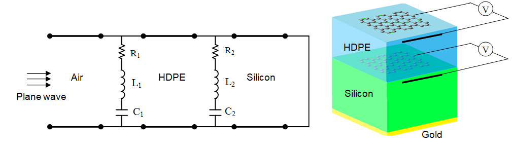
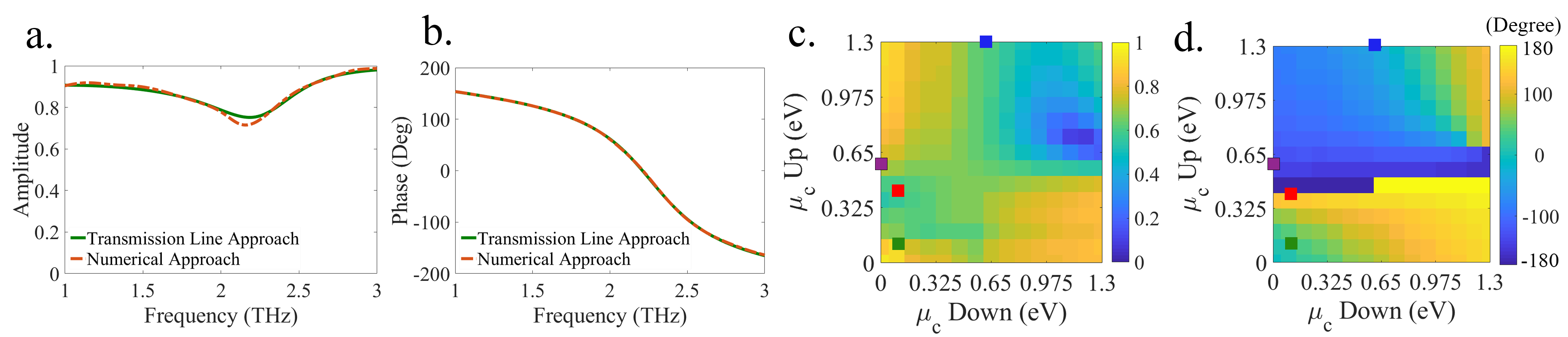
The third unit cell (Fig. 2(c)) is composed of a graphene-insulator-graphene stack placed over the substrate along with a ground plane on the backside. High-density polyethylene (HDPE) is chosen as the insulator due to its particularly low losses in the terahertz band [54]. The refractive index of the insulator is and its thickness is m. The equivalent circuit model of this structure consists of two parallel cells representing each of the graphene sheets. As shown in Fig. 5, this unit cell achieves a much wider phase variation, and by addressing each graphene patch independently, provides an extra degree of freedom to choose the states of the metasurface.
Regarding fabrication feasibility of the proposed low-profile structure (10 m substrate), there are advanced Silicon substrate thinning techniques that can be used to achieve an ultra-thinning down to 4 m without damage occurred due to thinning processes [55].
II-C Unit Cell Discrete States
The results above show the response of the metasurface for a continuous range of chemical potentials. However, in order to design a bit-programmable metasurface, we need to discretize the potentials to obtain a finite set of addressable states.
The first decision concerns the number of target states, and thus, the number of bits required to address a unit cell. Here, the number of states will determine the phase difference between consecutive unit cell states. For the application at hand, there is a relation between the phase difference and the steering resolution, i.e., the angle difference between consecutive achievable beam directions (see Sec. V for details). Therefore, the number of bits must be chosen carefully.
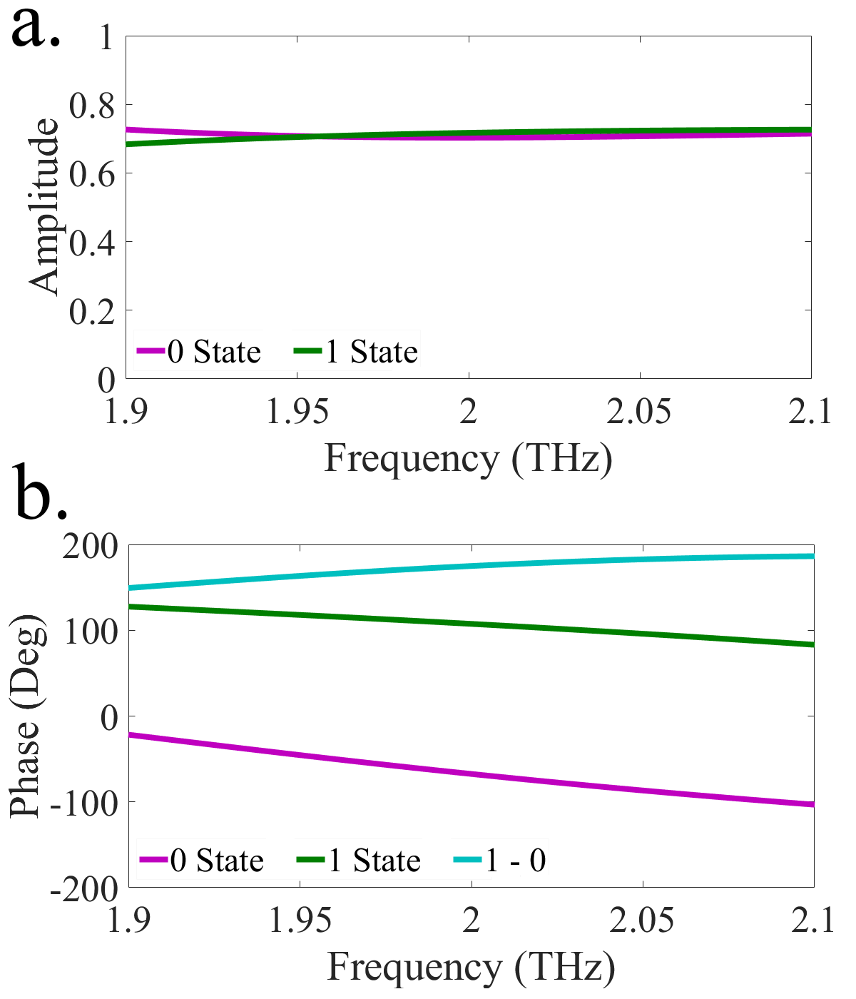
Let us now exemplify this process by deriving the states required for the metasurface to work at 2 THz. We start by addressing the 1G unit cell with a single bit. From the design space exploration shown in Fig. 4, we choose design points that have high amplitude and a phase difference of approximately 180o. A good choice is m with eV corresponding to a bit combination of . The resulting amplitude and phase responses, illustrated in Fig. 6, provide a constant reflection coefficient of around 0.7 and deliver the targeted 180o phase shift.
Two-bit coding leads to a phase shift resolution of 90o and would improve the beam steering accuracy substantially. The 1G unit cell, however, barely meets the amplitude and phase shift requirements with a 90o resolution. With m, there is no combination of chemical potentials capable of avoiding the region of low amplitude around 0.9 eV. For larger patch sizes, the phase response is not wide enough to accommodate two bits. For three or more bits, this unit cell would not be suitable for beam steering, at least for the relaxation time values and geometry considered in this work.
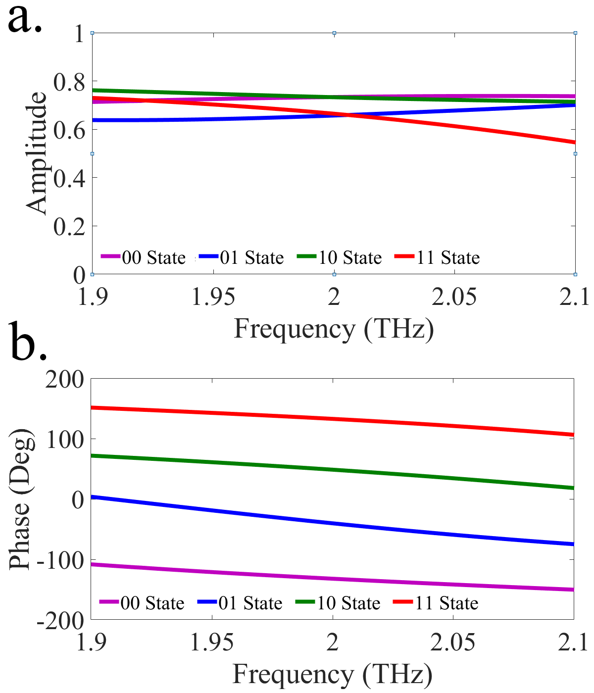
Alternatively, the 2G unit cell offers much more freedom and is capable of accommodating two or more bits. Addressing the 2G unit cell with two bits, one can find suitable design points with m. Using the design space exploration from Fig. 5, good performance is obtained for the following up-layer and down-layer chemical potentials, respectively: eV and eV corresponding to the bit combinations . It is observed in Fig. 7 that these states consistently achieve a reflection coefficient around 0.7 and a phase difference of 90o covering the whole phase space. In Section IV, we discuss how to electronically achieve these states.
III Coding Metasurface Terahertz Antenna
To illustrate the design approach of a terahertz metasurface for beam steering application, a metasurface including controllable unit cells is considered. Our design allows one to introduce a phase gradient by smartly changing the chemical potential of the graphene sheets from one unit cell to another. In this case, we need to use the generalized reflection law to evaluate the response of the metasurface [56].
In the following, we first derive the conditions required to achieve beam steering to a desired direction in Section III-A. Then, we define the design and configuration flow to achieve such the desired direction by our proposed design in Section III-B. Finally, we evaluate the performance of the proposed metasurface in Section III-C.
III-A Generalized Reflection Law Formulation
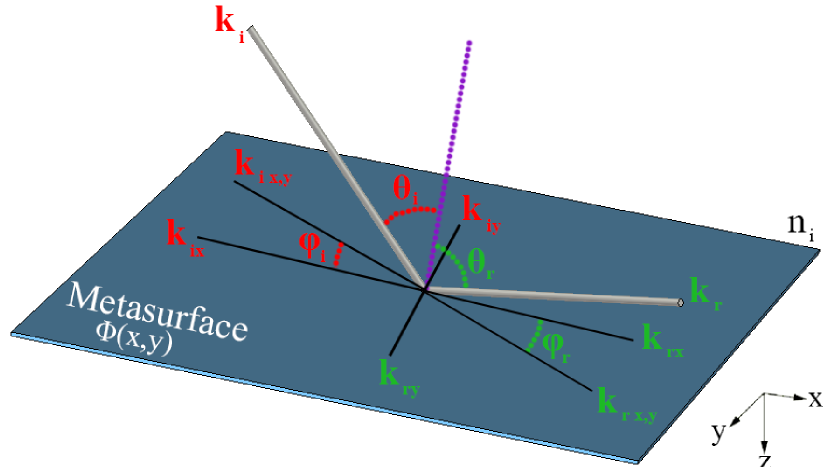
Consider a reflective metasurface under illumination of an incident plane wave at elevation angle and azimuth angle according to the coordinate system shown in Fig. 8. The incident wave vector can be written as
| (2) |
where are the wave vector coordinates, by
| (3) |
The same formulation can be applied to the reflected wave vector given the elevation angle and azimuth angle of the reflected wave.
Assuming that the metasurface imposes the phase profile , we assign it the virtual wave vector so that
| (4) |
where and are the phase gradients along the and directions, respectively.
Applying the boundary conditions of the tangential components of the electromagnetic fields, the momentum conservation law for wave vectors can be expressed as
| (5) |
and substituting (3) and (4) in (5) yields
| (6) |
By mathematically simplifying the above equations as shown in the Appendix, the reflected elevation angle and azimuth angle are obtained as
| (7) |
When the metasurface is illuminated by a normally incident wave (), and assuming air as the medium of the incident and reflected wave, we can simplify the formulas as
| (8) |
which relates the phase gradient in the metasurface to the direction of the reflected wave.
III-B Design Flow
Using (8), the reflected angles for all phase profiles of the metasurface can be calculated. The design of the metasurface can be then thought as an inversion process. We need to estimate the necessary phase profile to achieve the desired elevation and azimuth angles of the reflected wave. To this end, and again assuming a normal incident plane wave and air as the medium, we can rearrange (6) as
| (9) |
where describes the phase difference between adjacent unit cell states. Starting from here, the design methodology requires the knowledge of the unit cell dimensions and the number of states. The design flow is as follows,
1. Obtaining the cluster size (in m): Assume that the coding metasurface can choose among states for each unit cell (referred to as -bit coding). In this case, the granularity of the gradient is . Therefore, the lateral dimensions of the required cluster of unit cells ( and ), as shown in Fig. 1, are obtained by substituting in Eq. (9),
| (10) |
It is worth noting that the results in (9) can be negative if becomes negative, which implies that the gradient needs to be reversed at the coding stage. We will later see that the algorithm for metasurface coding already takes the direction of the gradient into consideration. Also, the value of determines the difference between and , which impacts on the shape of the reflected beam. The larger difference results in the more elliptical shape of the reflected beam.
2. Obtaining the cluster size (in number of unit cells): The nature of a metasurface, consisting an array of unit cells, dictates the discretization of space. Therefore, the values of and needs to be approximated in an integer number of unit cells. For this purpose, we consider that the number of unit cells in the and directions, designated by and , respectively, are rounded as
| (11) |
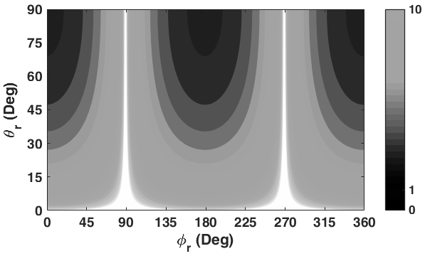
Figure 9 shows the absolute value of as a function of the target direction for a normally incident plane wave. It is observed that becomes arbitrarily large as the reflected angle approaches (white areas of the figure). This is consistent with the fact that such direction implies specular reflection, which can only be realized with a homogeneous surface, i.e. zero gradient. For directions approaching , also becomes large because the gradient is only needed in the axis. On the contrary, approaches zero in the co-planar directions, where an infinite gradient would be required. The black area in Fig. 9 denotes , which is unfeasible.
3. Obtaining the size of the super unit cell: To calculate the size of the super unit cell, designated by and , in number of unit cells, one needs to apply
| (12) |
III-C Evaluation
In this section, we evaluate the proposed metasurface both numerically and analytically. We numerically model the four states of the unit cell in CST [53], and apply the formulation developed above to assign the states to different unit cells of an metasurface. Then, we obtain the response of the metasurface in the form of the far field pattern produced by a normally incident plane wave. We assume that the beam covers the whole metasurface.
| Direction | ||||||||
|---|---|---|---|---|---|---|---|---|
| (m) | (cells) | (o) | (%) | |||||
| {30o, 45o} | 61.24 | 106.07 | 3 | 5 | 5 | 5.25 | 2.5 | 3.3 |
| {130o, 30o} | 116.68 | 97.91 | 6 | 5 | 8.25 | 4.75 | 0.58 | 4.16 |
| {230o, 20o} | 170.57 | 143.13 | 8 | 7 | 10.5 | 4 | 0.11 | 6.25 |
| {340o, 60o} | 46.08 | 126.6 | 2 | 6 | 4.5 | 8.25 | 0.15 | 3.75 |
In the analytical approach that is used to verify the numerical results, the reflection phase of each unit cell of size is assumed to be exactly either 0, , , or . Assuming a designed phase distribution assigned to the unit cells, we can express the far-field scattering pattern as
| (13) |
where and are the elevation and azimuth angles of an arbitrary direction, respectively, and and are the element factor (pattern function of unit cell) and array factor (pattern function of unit cell arrangement), respectively. Here, the unit cells are assumed to be isotropic, and therefore the scattering pattern depends only on the array factor
| (14) |
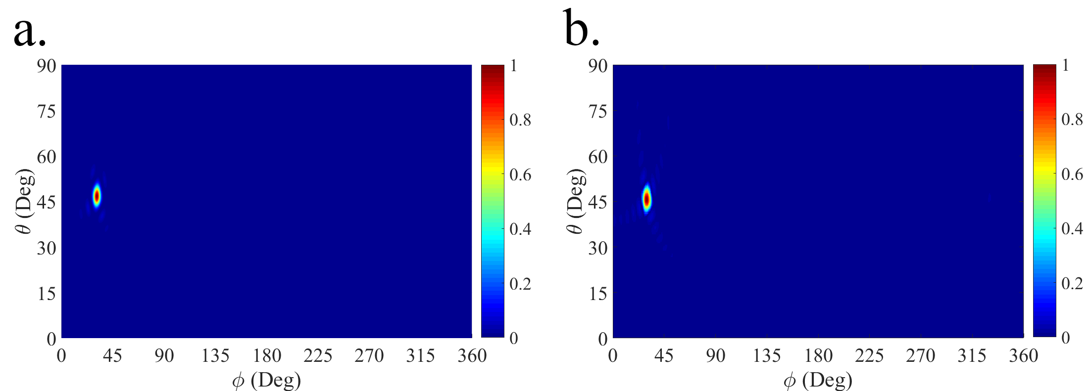
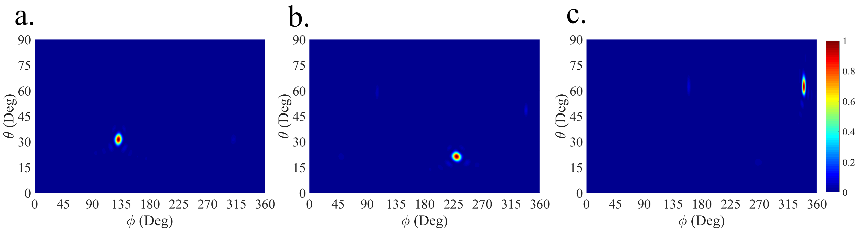
We first evaluate the metasurface when configured to steer the beam at with . Following the design flow from Section III-B and assuming 20-m unit cells and 2-bit coding, we obtain that m and m, which leads to a cluster of . The super unit cell thus extends for unit cells. Figure 10 shows the far field pattern of the resulting metasurface, which confirms that there is a good agreement between the numerical and analytical solutions. The reason for the small differences between the numerical and theoretical results in sidelobe levels could be the marginal unit cells in the clusters, super unit cells, and the whole structure. We obtain the amplitude and phase of the reflection coefficient of the proposed unit cells while taking into consideration mutual coupling between the same adjacent unit by assuming a periodic boundary condition. While in the real metasurface structure for beam steering, there are some marginal unit cells which their adjoining unit cells are not similar with them. Consequently, the peridicity condition is broken. In the simulation of full structure, the correct coupling of marginal unit cells is considered while in the theoretical analysis of entire metasurface structure, it is ignored perforce. It is seen that the reflected beam indeed points to the target direction. The steering error, evaluated as the difference between the target and achieved angles, is 2.5% and 3.3% in and , respectively. The 3-dB width of the beam is approximately 5o in both cases.
To further verify the validity of the approach, we reconfigure the metasurface to operate at three different steering directions. Figure 11 shows how the proposed metasurface design is capable of achieving the desired responses and Table I summarizes the characteristics and performance of the resulting configurations. A wide range of reflected angles is achieved with clusters of 2–8 unit cells, achieving in all cases beam widths below 11o (minimum 4o) with steering error below 7% (minimum 0.11%). Note that the error and beam width generally increase when approaching forbidden areas in the design space, where the gradient tends to zero or infinity. Also, the reflected beam for the cases {30o, 45o} and {340o, 60o} especially the latter) tend to be elliptical due to the larger difference between and , as hinted in Section III-B. In addition, to achieve a continuous beam scanning ability of coding metasurface with minimum angle variation, the convolution approach can be leveraged to steer the far-field pattern to a predetermined direction [57]. Regarding the Fourier relation between the field distribution on the coding metasurface and the resultant scattering pattern in the far-field, one can shift the reflected pencil beam by adding the two calculated phase gradient coding so that the total phase gradient deflection angle is equal to the desired angle.
IV Programmability and Implementation Issues
The final steps in the design of our beam steering device relate to the elements that control and excite the metasurface. More precisely, we need to conceive a setup that takes the target reflected angle as input and modifies the metasurface accordingly. To this end, in Sec. IV-A we propose a controller that automatically converts the target reflected angle into a bit matrix defining the states of each unit cell. Then, in Sec. IV-B we discuss the biasing scheme required to address each unit cell with the appropriate voltage (chemical potential). Finally, we review source considerations in Sec. IV-C.
IV-A Controller Design
To achieve programmability, it is necessary to attach the metasurface to a digital device capable of translating the beam steering requirements into the global metasurface state. Algorithm 1 shows a pseudocode that exemplifies this function. The process starts by calculating the size of the unit cell clusters as a function of the bit number per cell , and the dimension of the unit cell . Then, the gradient can be built easily by assigning consecutive states to adjacent clusters of unit cells. As already mentioned in Section III-B, (10) and (11) can produce negative values, in which case the order of states is reversed.
Algorithm 1 assumes that all unit cells are addressed by a centralized device, probably an FPGA. However, since the metasurface implements a discretized gradient, it would be relatively straightforward to come up with an algorithm that can calculate the required state in a distributed way, only relying on the state of the immediate neighbour. Such simplified scheme would be suitable for the rising Software-Defined Metamaterial (SDM) paradigm [58, 59], which aims to provide programmable metamaterials that can be reconfigured via an integrated network of controllers that drive unit cells individually. In that case, an external entity called gateway would receive the command of changing the direction of the beam. The gateway would compute and , then rely them to the first controller together with . The first controller would be initialized and pass its state along with , , and to their neighbours, which would repeat the process until the whole metasurface is programmed.
IV-B Actuator Design
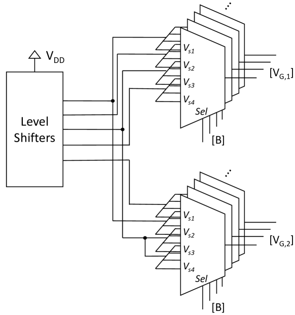
The actuator is a circuit that translates the state matrix provided by the controller into the matrix of appropriate voltages that, in turn, leads to the required chemical potentials in each graphene patch of the metasurface. As shown in Fig. 12, a set of voltage level shifters and a matrix of multiplexers would be enough for this purpose. Note that several independent sets of multiplexers (two in our case) may be required to drive the graphene patches of individual unit cells. It is also worth noting that only five distinct voltages are needed in our case, because several states share the same target chemical potentials according to the calculations made in Section II-C.
The actual voltages required at the output of the level shifters mainly depend on the graphene biasing structure and the required chemical potential [32, 60]. The configuration assumed in this paper is similar to that used in [32], which couples graphene capacitively with a back gate through a thin Al2O3 layer. Essentially, this scheme shifts the operation of graphene between the Dirac point, where the chemical potential is minimum, and a point where the potential reaches the maximum desired point. The resulting chemical potential relates to the change of voltage as
| (15) |
where is the elementary charge, is the reduced Planck constant, m/s is the Fermi velocity, is the vacuum permittivity, whereas and are the permittivity and thickness of the material below graphene [61].
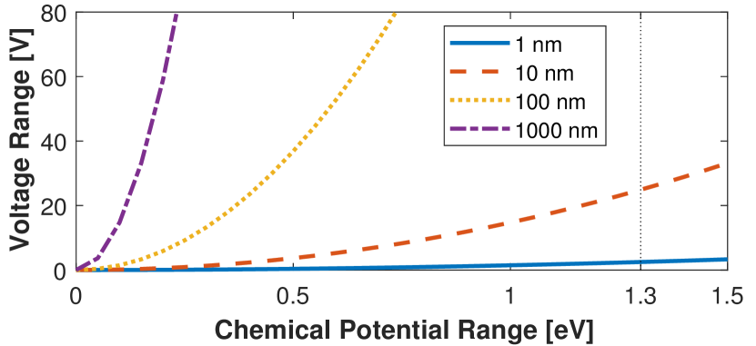
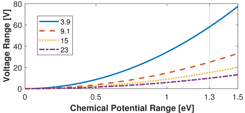
Figure 13 illustrates the voltage ranges required to achieve a certain target chemical potential range. As directly implied by (15), the voltage requirements increase quadratically with the target chemical potential range. To limit the requirements, one can either minimize the space between the gate and the graphene layer or use materials with high dielectric constant. However, the former is determined by technological constraints, and the latter needs to take into consideration the cost and other characteristics of the material.
The chemical potential range required by our metasurface can be obtained easily once the unit cell states are defined. In the present design, eV. Assuming a Al2O3 layer () with thickness nm, achievable with current technologies [32], the resulting voltage range is 24.9 V.
IV-C Towards an Experimental Setup
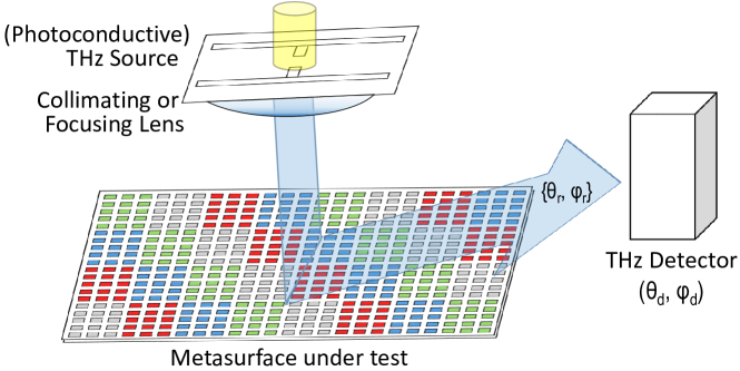
Figure 14 illustrates a possible measurement setup for the experimental of the metasurface. [11, 17] [62]
V Discussion
In this section, we qualitatively discuss several cross-cutting issues related to the design of the metasurface.
Scalability analysis: To accommodate the proposed design flow to different beam steering specifications, it is crucial to understand which are the key design parameters and what performance metrics do they affect. Here, we highlight some:
-
•
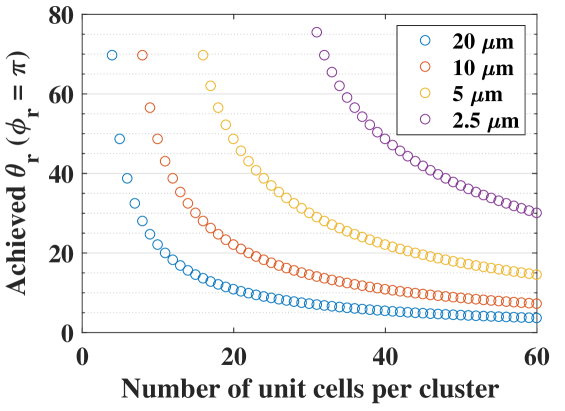
The size of the unit cell presents an interesting tradeoff. While it may be difficult to achieve a wide phase range if the unit cell is too small with respect to the wavelength (see Figs. 3 and 4), reducing its dimensions leads to a raise in the maximum achievable phase gradient. This is useful to achieve better control at the end-fire directions (o) of the metasurface, as exemplified by Fig. 15(a). For instance, we can achieve beam steering at o only for m. For angles even closer to o, a design converting the incident wave into a surface wave may be required [63]. In any case, note that such fine-grained control at THz frequencies can only be achieved with graphene, thanks to its support of plasmonic slow-wave propagation in this frequency band.
-
•
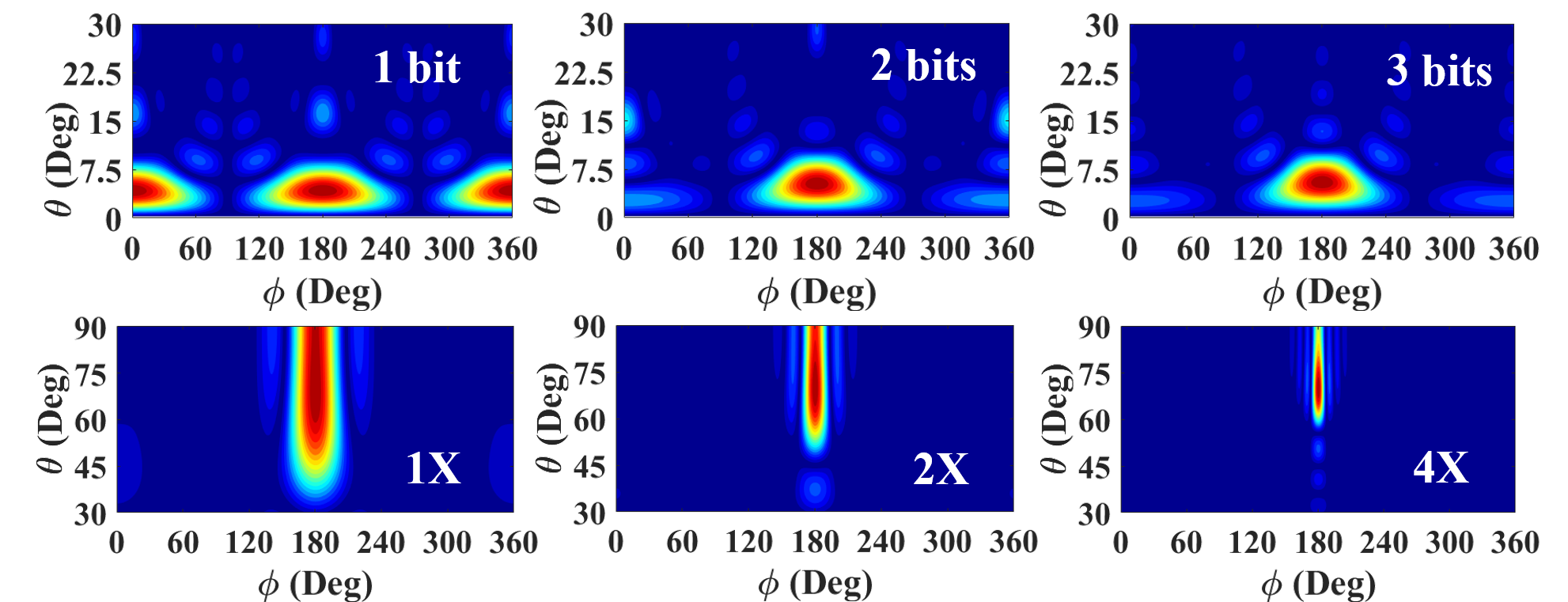
Increasing the number of bits provides better control on the phase as it allows to draw the phase gradient more accurately, with more clusters and less unit cells per cluster. This is of special importance in directions close to the boresight (o), where a subtle gradient is required. Fig. 15(b) exemplifies this for a design targeting o with fixed size, but increasing number of bits. The 3-bit instance greatly reduces the side lobes and has its maximum at o, whereas the beam moves away from the desired direction for the 2-bit and 1-bit cases (4.92o and 4.22o, respectively). Note, however, that the gain in accuracy comes at the cost of a substantially higher complexity at the controller and the actuator.
-
•
In arrays, adding more antennas allows to reduce the beam width. The same principle should apply in our design, as exemplified in Section III-C with the array factor formulation. We verified such hypothesis by fixing the gradient and doubling the number of supercells once and twice (from to ). The resulting far field patterns, shown in Fig. 15(b), clearly demonstrate that the beam is sharpened without significantly changing the direction of maximum energy. In fact, the beam width is reduced by a factor proportional to the increase in metasurface size, i.e. from 50o and 5o to 12o and 1.3o in the and angles, respectively.
Co-design opportunities: Understanding the design flow from the point of view of the unit cell, the metasurface, or the device as a whole helps to identify possible co-design opportunities. For instance, the unit cell configuration and the coding determine the complexity in terms of number of required voltage levels, as well as the quantity and size of the multiplexers. For an -bit coding with independently biased graphene patches, we may require up to levels and multiplexers with inputs. However, advanced design exploration techniques may allow to find design points that reduce the voltage range, the number of required levels, and the multiplexer inputs while gracefully degrading the performance of the system. For instance, in our 2-bit implementation with the unit cell, we could take and still achieve reasonable performance, but with a reduction of voltage range and number of levels and greatly simplfying the multiplexing circuits.
Adaptive clusterization: The strength of the proposed design flow is its simplicity. By fixing the cluster size first and then statically building the super cells, the state matrix can be calculated easily. However, the rounding operation used in the number of unit cells per cluster (Equation (11)) introduces an error, specially for large unit cells, that is later amplified by the static building of super cells. Both issues can be alleviated by simply inverting the design flow, i.e. obtaining the size of the super cell first, and then breaking it down into unequal clusters. For instance, a super cell composed by 18 unit cells can be coded with 4, 5, 4, and 5 unit cells per state; otherwise, the super cell would be statically coded to either 4 or 5 unit cells per state, leading to a significant error. In a similar approach, the coding algorithm could dynamically adapt the number of states, using fewer bits in those directions that require a very large gradient.
VI Conclusion
This paper has presented the complete design, from the unit cell up to the programming algorithm, of a reconfigurable digital metamaterial for beam steering in the terahertz band. The tunability of graphene is exploited at the unit cell level to provide a phase range close to , whereas the generalized Snell’s law of reflection has been used to derive the phase gradients required to target the beam to the desired direction. The results confirm the validity of the approach, which for normal incidence achieves a very broad reflection range with angle-dependent beam widths and steering errors. Considering normal incidence, the analytical formulation also models forbidden (and unreasonable) reflection directions effectively as infinite gradients. Finally, the scalability analysis confirms that the beam width depends on the size of the metasurface, the reflection range depends on the size of the unit cells, and the steering error and side lobe levels depend on the number of phases that the graphene-based unit cells can implement. Future works could leverage the comprehensive methodology developed herein to optimize the unit cell design and phase gradient formation to reduce the overhead of the solution and further improve the beam steering performance.
Acknowledgment
This work has been partially funded by Iran’s National Elites Foundation (INEF), the Spanish Ministry of Economía y Competitividad under grant PCIN-2015-012, and by ICREA under the ICREA Academia programme. Also, the authors would like to thank Christoph Süßmeier and the anonymous reviewers for their invaluable feedback.
Appendix
To extract from (6), we divide both expressions and apply basic trigometry to obtain
| (16) |
which yields
| (17) |
To extract from (6), we square and sum both expressions:
| (18) |
which, after applying basic trigonometry, becomes
| (19) |
Isolating, we obtain
| (20) |
References
- [1] H. T. Chen, A. J. Taylor, and N. Yu, “A review of metasurfaces: Physics and applications,” Reports on Progress in Physics, vol. 79, no. 7, 2016.
- [2] S. B. Glybovski, S. A. Tretyakov, P. A. Belov, Y. S. Kivshar, and C. R. Simovski, “Metasurfaces: From microwaves to visible,” Physics Reports, vol. 634, pp. 1–72, 2016.
- [3] P. Y. Chen and A. Alù, “Mantle cloaking using thin patterned metasurfaces,” Physical Review B - Condensed Matter and Materials Physics, vol. 84, no. 20, pp. 1–13, 2011.
- [4] X. Chen, L. Huang, H. Mühlenbernd, G. Li, and B. Bai, “Dual-polarity plasmonic metalens for visible light,” Nature Communications, no. 3, p. 1198, 2012.
- [5] L. Li, T.-J. Cui, W. Ji, S. Liu, J. Ding, X. Wan, Y. Bo Li, M. Jiang, C. W. Qiu, and S. Zhang, “Electromagnetic reprogrammable coding-metasurface holograms,” Nature Communications, vol. 8, no. 1, pp. 1–7, 2017.
- [6] S. Vellucci, A. Monti, M. Barbuto, A. Toscano, and F. Bilotti, “Satellite Applications of Electromagnetic Cloaking,” IEEE Transactions on Antennas and Propagation, vol. 65, no. 9, pp. 4931–4934, 2017.
- [7] A. C. Tasolamprou, T. Koschny, M. Kafesaki, and C. M. Soukoulis, “Near-Infrared and Optical Beam Steering and Frequency Splitting in Air-Holes-in-Silicon Inverse Photonic Crystals,” ACS Photonics, vol. 4, no. 11, pp. 2782–2788, 2017.
- [8] O. Tsilipakos, A. C. Tasolamprou, T. Koschny, M. Kafesaki, E. N. Economou, and C. M. Soukoulis, “Pairing Toroidal and Magnetic Dipole Resonances in Elliptic Dielectric Rod Metasurfaces for Reconfigurable Wavefront Manipulation in Reflection,” Advanced Optical Materials, vol. 6, no. 22, 2018.
- [9] S. W. Qu, W. W. Wu, B. J. Chen, H. Yi, X. Bai, K. B. Ng, and C. H. Chan, “Controlling Dispersion Characteristics of Terahertz Metasurface,” Scientific Reports, vol. 5, p. 9367, 2015.
- [10] Y. Zhang, L. Liang, J. Yang, Y. Feng, B. Zhu, J. Zhao, T. Jiang, B. Jin, and W. Liu, “Broadband diffuse terahertz wave scattering by flexible metasurface with randomized phase distribution,” Scientific Reports, vol. 6, p. 26875, 2016.
- [11] S. Liu, T. J. Cui, Q. Xu, D. Bao, L. Du, X. Wan, W. X. Tang, C. Ouyang, X. Y. Zhou, H. Yuan, H. F. Ma, W. X. Jiang, J. Han, W. Zhang, and Q. Cheng, “Anisotropic coding metamaterials and their powerful manipulation of differently polarized terahertz waves,” Light: Science and Applications, vol. 5, no. 5, pp. e16 076–11, 2016.
- [12] S. W. Qu, H. Yi, B. J. Chen, K. B. Ng, and C. H. Chan, “Terahertz Reflecting and Transmitting Metasurfaces,” Proceedings of the IEEE, vol. 105, no. 6, pp. 1166–1184, 2017.
- [13] G. Oliveri, D. Werner, and A. Massa, “Reconfigurable electromagnetics through metamaterials - A Review,” Proceedings of the IEEE, vol. 103, no. 7, pp. 1034 – 1056, 2015.
- [14] F. Liu, A. Pitilakis, M. S. Mirmoosa, O. Tsilipakos, X. Wang, A. C. Tasolamprou, S. Abadal, A. Cabellos-Aparicio, E. Alarcón, C. Liaskos, N. V. Kantartzis, M. Kafesaki, E. N. Economou, C. M. Soukoulis, and S. Tretyakov, “Programmable Metasurfaces: State of the art and Prospects,” in Proceedings of the ISCAS ’18, 2018.
- [15] F. Liu, O. Tsilipakos, A. Pitilakis, A. C. Tasolamprou, M. S. Mirmoosa, N. V. Kantartzis, D.-h. Kwon, M. Kafesaki, C. M. Soukoulis, and S. A. Tretyakov, “Intelligent Metasurfaces with Continuously Tunable Local Surface Impedance for Multiple Reconfigurable Functions,” Phys. Rev. Applied, vol. 11, no. 4, p. 044204, 2019.
- [16] S. Liu and T. J. Cui, “Concepts, working principles, and applications of coding and programmable metamaterials,” Advanced Optical Materials, vol. 5, no. 22, p. 1700624, 2017.
- [17] L. Liang, M. Qi, J. Yang, X. Shen, J. Zhai, W. Xu, B. Jin, W. Liu, Y. Feng, C. Zhang, H. Lu, H. T. Chen, L. Kang, W. Xu, J. Chen, T. J. Cui, P. Wu, and S. Liu, “Anomalous Terahertz Reflection and Scattering by Flexible and Conformal Coding Metamaterials,” Advanced Optical Materials, vol. 3, no. 10, pp. 1374–1380, 2015.
- [18] C. Della Giovampaola and N. Engheta, “Digital metamaterials,” Nature Materials, vol. 13, no. 12, pp. 1115–1121, 2014.
- [19] T. J. Cui, M. Q. Qi, X. Wan, J. Zhao, and Q. Cheng, “Coding Metamaterials, Digital Metamaterials and Programming Metamaterials,” Light: Science & Applications, vol. 3, 2014.
- [20] H. Yang, X. Cao, F. Yang, J. Gao, S. Xu, M. Li, X. Chen, Y. Zhao, Y. Zheng, and S. Li, “A programmable metasurface with dynamic polarization, scattering and focusing control,” Scientific Reports, vol. 6, no. 35692, 2016.
- [21] C. Huang, B. Sun, W. Pan, J. Cui, X. Wu, and X. Luo, “Dynamical beam manipulation based on 2-bit digitally-controlled coding metasurface,” Scientific Reports, vol. 7, no. January, pp. 1–8, 2017.
- [22] K. S. Novoselov, V. I. Fal’Ko, L. Colombo, P. R. Gellert, M. G. Schwab, and K. Kim, “A roadmap for graphene,” Nature, vol. 490, no. 7419, pp. 192–200, 2012.
- [23] Y. Wu, K. A. Jenkins, A. Valdes-Garcia, D. B. Farmer, Y. Zhu, A. Bol, C. Dimitrakopoulos, W. Zhu, F. Xia, P. Avouris, and Y.-M. Lin, “State-of-the-art graphene high-frequency electronics,” Nano letters, vol. 12, no. 6, pp. 3062–7, jun 2012.
- [24] T. Low and P. Avouris, “Graphene plasmonics for terahertz to mid-infrared applications,” ACS Nano, vol. 8, no. 2, pp. 1086–1101, 2014.
- [25] S. E. Hosseininejad, E. Alarcón, N. Komjani, S. Abadal, M. C. Lemme, P. Haring Bolívar, and A. Cabellos-Aparicio, “Study of hybrid and pure plasmonic terahertz antennas based on graphene guided-wave structures,” Nano Communication Networks, vol. 12, pp. 34–42, 2017.
- [26] J. M. Jornet and I. F. Akyildiz, “Graphene-based plasmonic nano-transceiver for terahertz band communication,” in Proceedings of the EuCAP ’14, 2014, pp. 492–6.
- [27] D. Correas-Serrano and J. S. Gomez-Diaz, “Graphene-based Antennas for Terahertz Systems: A Review,” FERMAT, 2017. [Online]. Available: http://arxiv.org/abs/1704.00371
- [28] I. Llatser, C. Kremers, A. Cabellos-Aparicio, E. Alarcón, and D. N. Chigrin, “Comparison of the resonant frequency in graphene and metallic nano-antennas,” AIP Conference Proceedings, vol. 1475, pp. 143–145, 2012.
- [29] M. Tamagnone, J. Gomez-Diaz, J. R. Mosig, and J. Perruisseau-Carrier, “Reconfigurable terahertz plasmonic antenna concept using a graphene stack,” Applied Physics Letters, vol. 101, no. 21, p. 214102, 2012.
- [30] S. Hosseininejad and N. Komjani, “Comparative analysis of graphene-integrated slab waveguides for terahertz plasmonics,” Photonics and Nanostructures - Fundamentals and Applications, vol. 20, no. July, pp. 59–67, 2016.
- [31] S. E. Hosseininejad, M. Neshat, R. Faraji-Dana, S. Abadal, M. C. Lemme, P. Haring Bolívar, E. Alarcón, and A. Cabellos-Aparicio, “Terahertz Dielectric Resonator Antenna Coupled to Graphene Plasmonic Dipole,” in Proceedings of the EuCAP ’18, 2018.
- [32] Y. Huang, L. Wu, M. Tang, and J. Mao, “Design of a beam reconfigurable THz antenna with graphene-based switchable high-impedance surface,” IEEE Transactions on Nanotechnology, vol. 11, no. 4, pp. 836–842, 2012.
- [33] Z. Xu, X. Dong, and J. Bornemann, “Design of a Reconfigurable MIMO System for THz Communications Based on Graphene Antennas,” IEEE Transactions on Terahertz Science and Technology, vol. 4, no. 5, pp. 609–617, 2014.
- [34] S. E. Hosseininejad, S. Abadal, M. Neshat, R. Faraji-Dana, M. C. Lemme, C. Suessmeier, P. Haring Bolívar, E. Alarcón, and A. Cabellos-Aparicio, “MAC-Oriented Programmable Terahertz PHY via Graphene-based Yagi-Uda Antennas,” in Proceedings of the WCNC ’18, 2018.
- [35] E. Carrasco, M. Tamagnone, and J. Perruisseau-Carrier, “Tunable graphene reflective cells for THz reflectarrays and generalized law of reflection,” Applied Physics Letters, vol. 102, no. 10, 2013.
- [36] B. Orazbayev, M. Beruete, and I. Khromova, “Ultrafast beam steering based on graphene metamaterial,” in Proceedings of the EuCAP 2017, 2017, pp. 3896–3899.
- [37] S. E. Hosseininejad, K. Rouhi, M. Neshat, R. Faraji-Dana, A. Cabellos-Aparicio, S. Abadal, and E. Alarcón, “Reprogrammable Graphene-based Metasurface Mirror with Adaptive Focal Point for THz Imaging,” Scientific Reports, vol. 9, p. 2868, 2019.
- [38] K. Rouhi, H. Rajabalipanah, and A. Abdolali, “Real-Time and Broadband Terahertz Wave Scattering Manipulation via Polarization-Insensitive Conformal Graphene-Based Coding Metasurfaces,” Annalen der Physik, vol. 1700310, p. 1700310, 2017.
- [39] S. R. Biswas, C. E. Gutiérrez, A. Nemilentsau, I.-H. Lee, S.-H. Oh, P. Avouris, and T. Low, “Tunable Graphene Metasurface Reflectarray for Cloaking, Illusion and Focusing,” Physical Review Applied, vol. 9, no. 3, p. 034021, 2018.
- [40] Z. Chang, B. You, L. S. Wu, M. Tang, Y. P. Zhang, and J. F. Mao, “A Reconfigurable Graphene Reflectarray for Generation of Vortex THz Waves,” IEEE Antennas and Wireless Propagation Letters, vol. 15, pp. 1537–1540, 2016.
- [41] Y. Chen, X. Li, Y. Sonnefraud, A. I. Fernández-Domínguez, X. Luo, M. Hong, and S. A. Maier, “Engineering the Phase Front of Light with Phase-Change Material Based Planar lenses,” Scientific Reports, vol. 5, p. 8660, 2015.
- [42] J. Perruisseau-Carrier, F. Bongard, R. Golubovic-Niciforovic, R. Torres-Sanchez, and J. R. Mosig, “Contributions to the Modeling and Design of Reconfigurable Reflecting Cells Embedding Discrete Control Elements,” IEEE Transactions on Microwave Theory and Techniques, vol. 58, no. 6, pp. 1621–1628, 2010.
- [43] F. S. Ma, Y. S. Lin, X. H. Zhang, and C. Lee, “Tunable multiband terahertz metamaterials using a reconfigurable electric split-ring resonator array,” Light: Science & Applications, vol. 3, p. e171, 2014.
- [44] J. Wang, W. B. Lu, J. L. Liu, and T. J. Cui, “Digital Metamaterials Using Graphene,” Plasmonics, vol. 10, no. 5, pp. 1141–1145, 2015.
- [45] I. Akyildiz, J. Jornet, and C. Han, “TeraNets: ultra-broadband communication networks in the terahertz band,” IEEE Wireless Communications, vol. 21, no. 4, pp. 130–135, 2014.
- [46] I. F. Akyildiz, C. Han, and S. Nie, “Combating the Distance Problem in the Millimeter Wave and Terahertz Frequency Bands,” IEEE Communications Magazine, vol. 56, no. June, pp. 102–108, 2018.
- [47] I. F. Akyildiz and J. M. Jornet, “Realizing ultra-massive mimo (1024 1024) communication in the (0.06–10) terahertz band,” Nano Communication Networks, vol. 8, pp. 46–54, 2016.
- [48] X. Tan, Z. Sun, D. Koutsonikolas, and J. M. Jornet, “Enabling Indoor Mobile Millimeter-wave Networks Based on Smart Reflect-arrays,” in Proceedings of the INFOCOM ’18, 2018.
- [49] C. Liaskos, A. Tsioliaridou, A. Pitsillides, S. Ioannidis, and I. Akyildiz, “Using any Surface to Realize a New Paradigm for Wireless Communications,” Communications of the ACM, vol. 61, no. 11, pp. 30–33, 2018.
- [50] G. W. Hanson, “Dyadic Green’s Functions for an Anisotropic , Non-Local Model of Biased Graphene,” IEEE Transactions on Antennas and Propagation, vol. 56, no. 3, pp. 747–757, 2008.
- [51] S. Abadal, I. Llatser, A. Mestres, H. Lee, E. Alarcon, and A. Cabellos-Aparicio, “Time-domain analysis of graphene-based miniaturized antennas for ultra-short-range impulse radio communications,” IEEE Transactions on Communications, vol. 63, no. 4, pp. 1470–1482, 2015.
- [52] L. Banszerus, M. Schmitz, S. Engels, J. Dauber, M. Oellers, and P. Gr, “Ultra-high mobility graphene devices from chemical vapor deposition on reusable copper,” Science Advances, vol. 1, no. 6, p. e1500222, 2015.
- [53] “CST Microwave Studio.” [Online]. Available: http://www.cst.com
- [54] X. Zhou, T. Zhang, L. Chen, W. Hong, and X. Li, “A graphene-based hybrid plasmonic waveguide with ultra-deep subwavelength confinement,” Journal of Lightwave Technology, vol. 32, no. 21, pp. 4199–4203, 2014.
- [55] Y. Kim, S. Kodama, Y. Mizushima, N. Maeda, H. Kitada, K. Fujimoto, T. Nakamura, D. Suzuki, A. Kawai, K. Arai et al., “Ultra thinning down to 4-m using 300-mm wafer proven by 40-nm node 2gb dram for 3d multi-stack wow applications,” in 2014 Symposium on VLSI Technology (VLSI-Technology): Digest of Technical Papers. IEEE, 2014, pp. 1–2.
- [56] N. Yu, P. Genevet, M. A. Kats, F. Aieta, J.-P. Tetienne, F. Capasso, and Z. Gaburro, “Light propagation with phase discontinuities: generalized laws of reflection and refraction,” science, vol. 334, no. 6054, pp. 333–337, 2011.
- [57] S. Liu, T. J. Cui, L. Zhang, Q. Xu, Q. Wang, X. Wan, J. Q. Gu, W. X. Tang, M. Qing Qi, J. G. Han et al., “Convolution operations on coding metasurface to reach flexible and continuous controls of terahertz beams,” Advanced Science, vol. 3, no. 10, p. 1600156, 2016.
- [58] C. Liaskos, A. Tsioliaridou, A. Pitsillides, I. F. Akyildiz, N. V. Kantartzis, A. X. Lalas, X. Dimitropoulos, S. Ioannidis, M. Kafesaki, and C. M. Soukoulis, “Design and Development of Software Defined Metamaterials for Nanonetworks,” IEEE Circuits and Systems Magazine, vol. 15, no. 4, pp. 12–25, 2015.
- [59] S. Abadal, C. Liaskos, A. Tsioliaridou, S. Ioannidis, A. Pitsillides, J. Solé-Pareta, E. Alarcón, and A. Cabellos-Aparicio, “Computing and Communications for the Software-Defined Metamaterial Paradigm: A Context Analysis,” IEEE Access, vol. 5, pp. 6225–6235, 2017.
- [60] J. S. Gómez-Díaz, C. Moldovan, S. Capdevila, J. Romeu, L. Bernard, A. Magrez, A. Ionescu, and J. Perruisseau-Carrier, “Self-biased reconfigurable graphene stacks for terahertz plasmonics,” Nature Communications, vol. 6, no. 6334, pp. 1–8, 2015.
- [61] Y.-J. Yu, Y. Zhao, S. Ryu, L. E. Brus, K. S. Kim, and P. Kim, “Tuning the graphene work function by electric field effect,” Nano Letters, vol. 9, no. 10, pp. 3430–3434, 2009.
- [62] J. Kokkoniemi, V. Petrov, D. Moltchanov, J. Lehtomaki, Y. Koucheryavy, and M. Juntti, “Wideband Terahertz Band Reflection and Diffuse Scattering Measurements for Beyond 5G Indoor Wireless Networks,” in Proceedings of the EW ’16, 2016.
- [63] S. N. Tcvetkova, D. H. Kwon, A. Diaz-Rubio, and S. A. Tretyakov, “Nearly perfect conversion of a propagating wave into a surface wave,” in Proceedings of the ICEAA 2017, 2017, pp. 1426–1428.