Realization of doubly inhomogeneous waveplates for structuring of light beams
Abstract
Waveplates having spatially varying fast-axis orientation and retardance provide an elegant and easy way to locally manipulate different attributes of light beams namely, polarization, amplitude and phase, leading to the generation of exotic structured light beams. The fabrication of such doubly inhomogeneous waveplates (d-plates) is more complex, compared to that of singly inhomogeneous waveplates (s-plates) having uniform retardance, which can be easily fabricated by different means such as photoalignment of liquid crystals, metasurfaces etc. Here, exploiting the SU(2) formalism, we establish analytically that any d-plate can be equivalently implemented using a pair of quarter-wave s-plates and a half-wave s-plate. An important advantage of this method is that it gives the flexibility to realize a whole family of distinct d-plates using the same triplet of s-plates. To underline the scope of this method, we propose novel d-plates for spatially tailoring the phase and complex amplitudes of light beams. Towards complex amplitude shaping, we present a generic method for carving out higher-order eigenmodes of light using a d-plate in conjugation with a polarizer. A generalized q-plate-like gadget, for imparting a polarization-dependent phase profile to a scalar light beam, is proposed as a demonstration of phase-polarization interplay. For these two illustrations, the corresponding three-s-plate gadget is constructed, and its functioning is validated with extensive numerical simulations. The main result and its illustrations are generic and agnostic to the way the s-plates are fabricated and we believe they carry the potential to push the current state of the art in interdisciplinary applications involving structured light beams.
I Introduction
Waveplates have been indispensable workhorses in optics laboratories, extensively used for manipulating the state of polarization (SoP) of light beams. Traditionally, they are made from optically anisotropic materials and characterized by a uniform retardance and a unique orientation of fast-axis confined to its plane, classified here as homogeneous waveplates. One could also fabricate waveplates with spatial variation in either retardance or fast-axis orientation or both, and are here termed as inhomogeneous waveplates. For notational convenience, we classify the waveplates based on their inhomogeneity, into four kinds, as summarized in the Tab. (1).
| Kind | Retardance | fast-axis | |
|---|---|---|---|
| Homogeneous | Uniform | Uniform | |
| Singly inhomogeneous | 1 | Uniform | Nonuniform |
| (s-plate) | 2 | Nonuniform | Uniform |
| Doubly inhomogeneous | Nonuniform | Nonuniform | |
| (d-plate) | |||
A light beam with a spatially uniform SoP in its transverse plane, referred to as scalar beam, through a homogeneous waveplate exits as a scalar beam with a different SoP. In this process, it also picks-up a kind of geometric phase, called the Pancharatnam-Berry (PB) phase (pancharatnam1956generalized, ; berry1987adiabatic, ), whose magnitude depends on the retardance and fast-axis orientation of the waveplate, in addition to the input SoP. On the other hand, a scalar beam through an inhomogeneous waveplate would emerge out with a spatially varying SoP and/or phase. Light beams with spatially varying SoPs are termed as vector beams(zhan2009cylindrical, ; qiwen2013vectorial, ). Generation of light beams with spatially varying phase, i.e., wavefront shaping, is also possible using inhomogeneous waveplates, based on the idea of PB-phase. For instance a well-known s-plate of the first kind is the q-plate(marrucci2006optical, ), whose fast-axis varies linearly with the azimuthal angle. The standard q-plates have a retardance and a scalar light beam with circular polarization through it acquires a helical wavefront, in addition to flipped helicity in its polarization.
Such tailoring of light beams, with spatial variation in SoP, amplitude and phase, leads to a bigger class of light beams called structured light(andrews2011structured, ; rubinsztein2016roadmap, ; rosales2018review, ). In the recent past, structured light has found increased applications. For instance, radially polarized light, a kind of vector beams, are shown to provide sharper focusing in comparison with linearly polarized light (dorn2003sharper, ). Light beams with helical phase are known to carry orbital angular momentum(allen1992orbital, ; shen2019optical, ) and this concept has given birth to many novel phenomena in optics like: spin-orbit interactions(bliokh2015spin, ), spin-Hall effect(liu2017photonic, ) and these have shown promising applications too(shitrit2013spin, ; aiello2015transverse, ). Structuring of light has also contributed in, among others, optical trapping(kozawa2010optical, ; roxworthy2010optical, ; taylor2015enhanced, ), material processing(meier2007material, ) and quantum information tasks(erhard2018twisted, ).
The last couple of decades has therefore witnessed a flurry of activity towards designing inhomogeneous waveplates aimed at the generation of structured light beams. These efforts have been particularly successful with respect to s-plates, leading to diverse methods of fabricating them being established, prominent ones being those based on photoalignment of liquid crystals(Chigrinov2008, ; kim2015fabrication, ; ji2016meta, ) and metasurfaces(lin2014dielectric, ; khorasaninejad2016metalenses, ; scheuer2020optical, ). The richness offered by d-plates in applications is just beginning to be explored(ling2015giant, ; pal2016tunable, ; devlin2017arbitrary, ; rafayelyan2017laguerre, ; rubin2019matrix, ), their adaptation being slow perhaps due to the challenges in their fabrication. Use of metasurfaces for fabricating the d-plates is now picking up steam(arbabi2015dielectric, ; mueller2017metasurface, ), but it involves precise control of dimensions in the nano-meter length scale. Further, in this method the parameters of the d-plate get fixed at the time of fabrication and cannot be dynamically tuned. In liquid crystal based s-plates, on the other hand, it is possible to achieve active control of retardance through external means like applied voltage (piccirillo2010photon, ; Slussarenko:11, ) or temperature(Karimi2009, ), but, to the best of our knowledge, there has been no literature on fabrication of d-plates using liquid crystals.
These limitations in current methods of fabricating d-plates forces one to seek alternate ways of realizing them. In this context, it is interesting to explore whether a stack of s-plates can effectively function like a d-plate. Such effective waveplates, have earlier assisted in realizing many functionalities which otherwise are not possible through individual waveplates. For instance, early work of Pancharatnam demonstrated that a half-wave (HW) plate sandwiched between two identically oriented quarter-wave (QW) plates functions effectively as a tunable retardance waveplate and has been used for realizing achromatic waveplates(pancharatnam_1_1955achromatic, ; pancharatnam2_1955achromatic, ) and are even available commercially (thorlabs_Pancharatnam_achromat, ). Stacking of s-plates has also yielded many novel results. For instance, combination of q-plates and waveplates are used for changing the topological charges of q-plates(yi2015addition, ; delaney2017arithmetic, ). Passively tuning the retardance of q-plates is possible from a combination of q-plates wherein, the retardance is tuned by merely changing the relative orientation of the involved q-plates(radhakrishna2019wavelength, ).
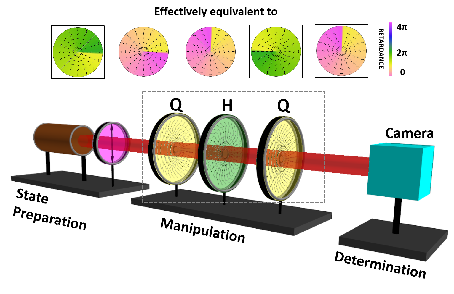
In this article, we first demonstrate that an arrangement involving a pair of identically oriented QW-s-plates with a HW-s-plate placed in between (henceforth referred to as QHQ-s-plate) is effectively equivalent to a d-plate. Conversely, given a d-plate, we establish that there exists a unique QHQ-s-plate equivalent to it and derive the fast-axis orientations of those s-plates. While local manipulation of SoPs of light using waveplates is well-studied, spatial structuring of its complex amplitude and phase is more involved and rarely discussed. Therefore as a strong demonstration of this equivalence, we theoretically propose novel d-plate based gadgets for local manipulation of amplitude and phase of light beams. For these two cases, we numerically simulate the corresponding QHQ-s-plate and validate its ability to mimic the d-plate. These examples are of significant interest and complexity in their own realm, and have spawned a large amount of literature.
The first illustration is that of tailoring the complex amplitude of light beams. Different varieties of light beams are studied in the literature(korotkova2013random, ), for instance Laguerre-Gaussian(LG) and Hermite-Gaussian(HG) beams(galvez2017complex, ), non-diffracting beams like Bessel beams(bouchal2003nondiffracting, ; mazilu2010light, ), accelerating beams(efremidis2019airy, ) and so on. Each of these beams have found numerous applications, for instance, in reducing the thermal noise of gravitational wave detectors (granata2010higher, ; tao2020higher, ), in STED microscopy(hell1994breaking, ; yu2016super, ), in optical tweezers(simpson1996optical, ; simpson1997mechanical, ) Bose-Einstein-condensation(wright2000toroidal, ) etc. Here, we demonstrate that starting from the fundamental Gaussian mode of light, higher-order LG and HG beams can be generated using a combination of d-plate and a polarizer. Similar strategy of realization has been employed in (rafayelyan2017laguerre, ; rafayelyan2017laguerre_nanostructure, ), but restricted to higher order LG-beams.
The next illustration is meant at designing a d-plate that imparts a polarization-dependent phase profile to the input scalar light beam. This, in a sense, generalizes the notion of q-plate to arbitrary elliptical polarization (instead of circular polarization) and arbitrary wavefront (instead of helical wavefront). This example also serves to bring out the limitation of d-plates in affecting PB-phase based SoP transformations.
II Theory
The SoP of a light beam refers to the direction of the time-varying electric field vector in its transverse plane. SoPs are described in different but equivalent ways, prominent ones being Jones vector, Stokes vector and as points on the Poincare sphere. The Jones vector of an SoP is a two-dimensional complex vector of unit norm given by:
| (1) |
where and are left and right circular polarizations respectively, which in the horizontal-vertical basis, and , are chosen to be and and , . One could also characterize the SoP by a three-dimensional real unit vector , called the Stokes vector whose explicit expression is
| (2) |
The Jones and Stokes vector representations of a polarization state are connected by(damask2004polarization, )
| (3) |
where is a Pauli-spin vector with components:
| (4) |
These SoPs can also be represented geometrically as points on the surface of a unit sphere, called the Poincare sphere. In this description, the SoP is mapped to the point whose polar and azimuthal coordinates are and respectively.
SoP of a light beam can be altered, without changing its intensity, by use of anisotropic optical elements called waveplates. They are characterized by two parameters: retardance and orientation of the fast-axis . They function by introducing a phase difference of between the electric field component along the fast-axis and its orthogonal direction. For instance QW-plate and HW-plate introduce a phase difference of and respectively. As waveplates merely introduce phase difference between the orthogonal components, they do not alter the intensity of the light beam. Hence, their action is mathematically described by norm-preserving matrices, which in Jones vector formalism are unitary matrices called Jones matrices and in Stokes vector formalism are orthogonal matrices.
By definition, Jones matrix of waveplates accounts for the linear transformation between two Jones vectors of SoPs. Jones vectors, however, are arbitrary up to a global phase factor, and hence waveplates that transform the SoPs can be represented by unitary matrices, without regard to the determinant. Nevertheless, for correct handling of the associated PB phase change, it is preferable to represent Jones matrices as unitary matrices of unit determinant, i.e., matrices (damask2004polarization, ). Therefore, in the rest of the article, the Jones matrices of waveplates are described using SU(2) matrices.
On the Poincare sphere, the action of a waveplate with parameters and , on an SoP is described as a rotation of its Stokes vector , about the rotation axis , by the angle . The Jones matrix of such a waveplate, denoted as , in the basis is given by:
| (5) | ||||
| (8) |
where is the identity matrix. It may be noted that is a symmetric matrix, with diagonal elements being complex conjugates of each other, and off-diagonal elements being purely imaginary.
For a stack of waveplates, their combined action is described by a matrix obtained by multiplying the Jones matrix of each waveplates. While the product of Jones matrices of waveplates is also an SU(2) matrix, it need not be a Jones matrix of the form of Eq. (8). However, if the resulting matrix is also of this form, then the sequence of waveplates effectively functions like a single waveplate , having an effective retardance and an effective fast-axis orientation which can be determined from the SU(2) matrix:
| (9) | ||||
| (10) |
where is the imaginary part of .
As mentioned in the previous section, an arrangement of HW-plate sandwiched between two identically oriented QW-plates acts like a single waveplate, with effective retardance depending on the relative orientation between the HW-plate and QW-plates, and effective fast-axis orientation inclined at an angle of with respect to the QW-plates. This arrangement of waveplates, called here as QHQ-waveplate, enables realizing a tunable retardance waveplate where the tuning is achieved by merely changing the relative orientation of the plates.
The above Jones matrix formalism of waveplates can be extended to s-plates and d-plates, except that now the matrix is a function of the radial and azimuthal coordinates of the plate, through or or both. For instance, the standard q-plate(marrucci2006optical, ) is the most studied s-plate of the first kind, with retardance , and fast-axis orientation varying linearly with the azimuthal angle as , where is the topological charge and is the offset angle. Its Jones matrix is therefore a function of azimuthal coordinate :
| (11) |
Here we extend the notion of QHQ-waveplate to such inhomogeneous waveplates and explore its effective behavior. Since the QHQ-arrangement is possible only with s-plates of first kind, in the rest of the article, s-plate always refers to the s-plate of first kind classified in the Tab. (1), unless mentioned otherwise.
Consider a HW-s-plate with fast-axis orientation placed in between two identically oriented QW-s-plates having fast-axis distribution . We refer to this QHQ arrangement of s-plates as the “QHQ-s-plate”. The effective retardance and the effective fast-axis orientation of the QHQ-s-plate is (see appendix A):
| (12) | ||||
| (13) |
It should be noted that the effective retardance acquires spatial dependence, and thereby converts the three s-plates into an effective d-plate. Conversely, and more importantly, any desired d-plate with and can be uniquely realized as QHQ-s-plate with and given by:
| (14) | ||||
| (15) |
It should be emphasized that the QHQ-s-plate is completely equivalent to the d-plate, not just in bringing about the SoP transformations but also in capturing the associated PB phases correctly. Moreover, an important advantage of realizing d-plate through this method is that a single set of QHQ s-plates can be employed for generating a variety of d-plates. This is possible by merely changing the orientations of three s-plates, constraining to the QHQ arrangement.
To elaborate, consider a QHQ-s-plate, having fast-axis variation of QW-s-plate and HW-s-plate as and respectively, set for realizing a d-plate with parameters and . Rotating these s-plates by angles and respectively about their axes results in new s-plates having and , see Eq. (42) of appendix (B). These new s-plates continue to remain in the QHQ arrangement and therefore yeild a new d-plate, with parameters and given by:
| (16) | |||||
| (17) |
The five insets in Fig. (1) depict the distinct d-plates realized using the same physical set of three s-plates but by rotating them constraining to QHQ arrangement.
In the following section, we explore the possible applications of these results towards spatial control of amplitude and phase of light beams.
III illustrations of structuring the light beam using d-plates
III.1 Tailoring the complex amplitude of light beams
In this subsection, a generic method for spatial tailoring of the amplitude and phase of light beams, using d-plates is proposed. As a demonstration of this technique, realization of higher order LG beams and HG beams starting from a fundamental Gaussian beam is discussed. We aim to tailor a desired complex electric field , starting from a scalar light beam having electric field . We achieve this by transforming the input scalar light beam using a d-plate, such that one of the components of the emerging vector beam, in a particular orthogonal basis, is . This component can be extracted by projecting out the orthogonal component. For concreteness, we work in basis, and let the SoP of the initial light beam be . The transformation briefed above can be achieved by an transformation :
| (18) |
where is the remnant electric field, satisfying the relation:
| (19) |
Assuming does not vanish within the region of interest,
| (20) |
Given the action of on its action on vertical polarization gets fixed because of its property:
| (21) |
where denotes the complex conjugation. Hence, the matrix of in the basis is given by
| (22) |
The matrix will correspond to the Jones matrix of a d-plate, as in Eq. (8), provided its off-diagonal elements are purely imaginary. The ratio appearing along the off-diagonal is , where and are the respective phases which, in general, can be spatially variant. As only the magnitude of is fixed through Eq. (19) leaving us free with the choice of , the off-diagonal entries can be rendered purely imaginary by setting , so that the resulting matrix can then be realized by a d-plate . Placing a polarizing beam splitter at the state determination stage (see Fig. (1)), yields the desired field in the horizontal arm and the remnant field in the vertical arm.
The required retardance and fast-axis orientation of the d-plate are extracted from the resulting matrix through Eqs. (9 and 10):
| (23) | |||||
| (24) |
It follows from Eqs. (23 and 24) that for the case of , the fast-axis orientation equals at all , reducing the d-plate to an s-plate of the second kind (see Tab. 1).
Here, we apply this idea towards simulating LG and HG modes of higher order. The functional forms of these modes are readily available, for instance(galvez2017complex, ). At the location of the beam waist , they simplify to:
| (25) |
| (26) |
where denotes the associated Laguerre polynomials with and being the azimuthal and radial indices of the LG beam respectively; refers to the Hermite polynomial of order ; is the beam waist and is a constant, indicating the power of the light beam.
We chose the input beam as the horizontally polarized fundamental Gaussian mode, since it is non-vanishing at all finite values of , thereby satisfying the condition required for Eq. (20). Placing the d-plate at the location of the input beam waist, we have
| (27) |
The LG and HG modes simulated are and respectively. The possible values for and is restricted through Eq. (19) which demands at all within the region of interest in the transverse plane, which in turn dictate the conversion efficiency of the d-plates.
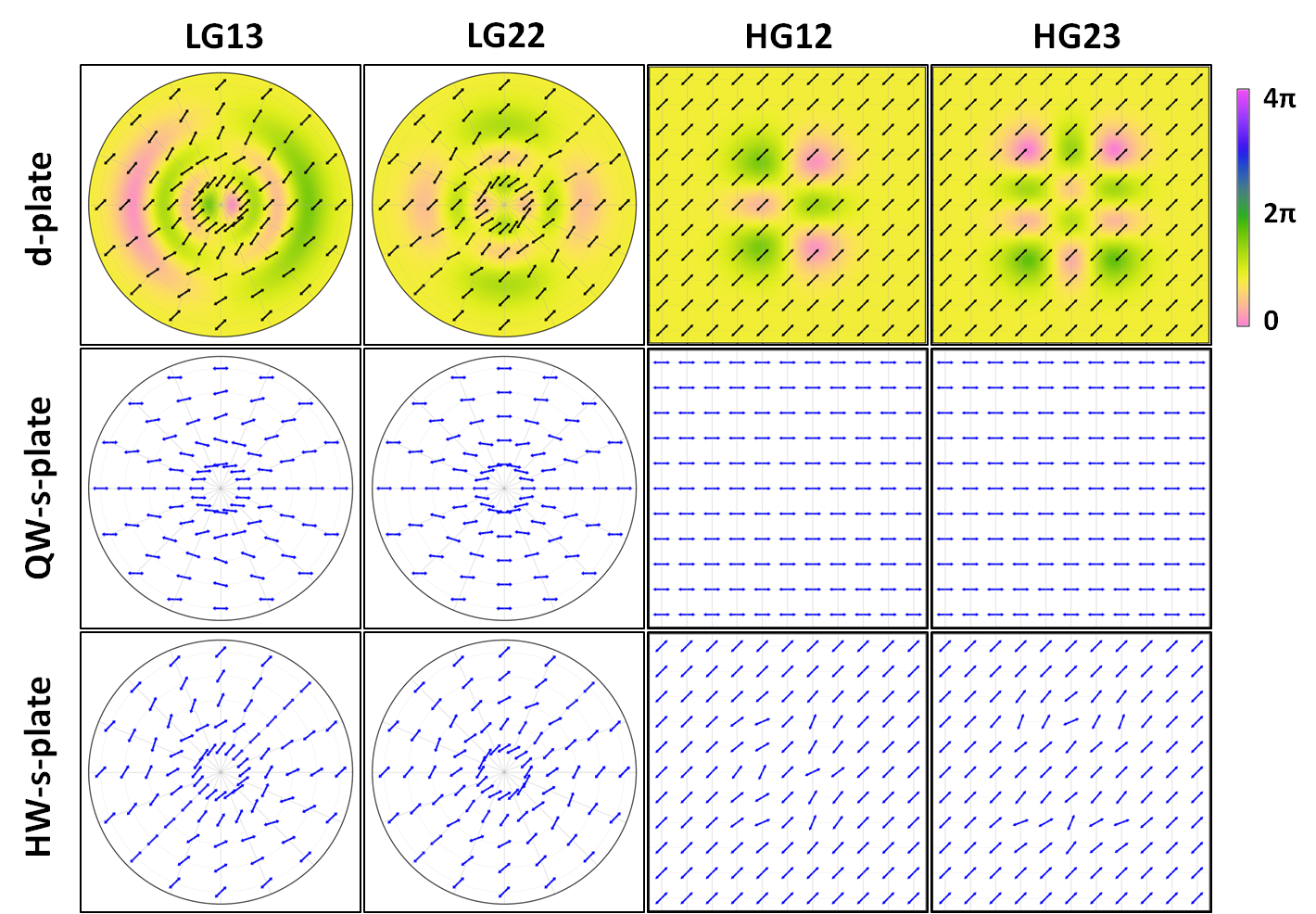
We now illustrate the working of this method by studying a few cases through numerical simulations. We consider = and in case of LG modes, and in case of HG modes, and . The values of and in all four cases are taken to be and respectively. The retardance and fast-axis orientations of the d-plates required for this apodization are calculated using Eqs. (23 and 24). The required fast-axis orientations of the QW-s-plates and HW-s-plate for realizing these d-plates are respectively determined using Eqs. (14 and 15) and are summarized in Fig. (2).
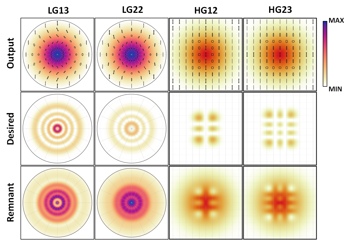
To validate the conversion to higher order modes, evolution of light through the QHQ-s-plates is numerically simulated, ignoring the diffraction and propagation effects. The input scalar beam, as it emerges out of the QHQ-s-plate, gets converted into a vector beam through Eq. (8). The numerically simulated intensity and SoP distributions in the transverse plane at the exit plane of these QHQ-s-plates is depicted in Fig. (3). The desired modes and remnant fields are contained in the horizontal and vertical component of these vector beams, which can be extracted by projecting them, for instance, using a polarizing beam splitter. Figure (3) summarizes the intensity distributions, and for all the four cases. The spatial distribution of intensity in the horizontal projection is consistent with that of the desired modes. The ratio of beam waists of output and input beams appears to be a crucial parameter in deciding the efficiency of conversion, as also observed in (rafayelyan2017laguerre, ).
To summarize this subsection, d-plate, together with a standard polarizer, can aid in sculpting any complex amplitude light beams, out of the ubiquitous fundamental Gaussian beams.
III.2 Arbitrary polarization-dependent wavefront shaping
Waveplates, apart from manipulating the SoP, also impart a total phase (=dynamic phase + geometric phase), which depends on the plate parameters and the involved SoPs. Given a pair of SoPs, there always exists a waveplate that transforms one state to other unitarily and picking up a particular phase in the process, depending on the path of transformation. Owing to the spatial inhomogeneity of their fast-axis orientation, s-plates are capable of imparting desired phase distribution onto the input light beam. In these lines, the most studied s-plates are the q-plates which basically flip the handedness of the input circular polarization, and impart a helical phase in the process. In this subsection, we seek to extend this functioning of q-plates to arbitrary SoPs instead of circular polarizations, and to arbitrary phase distributions instead of helical phase. The mathematical treatment required in the conversion of an arbitrary SoP into an SoP of flipped handedness, and with arbitrary phase distribution is first discussed. A d-plate based gadget is designed to impart a polarization-dependent phase distribution to the input light beam.
In general, using a waveplate it is not possible to transform SoPs with a given phase, as the possible rotation axes for transforming them are limited to two directions, thereby restricting the number of phases to two. This stems from the fact that, the midplane of the SoPs involved intersects the equatorial plane at only two points on the Poincare sphere (which are antipodal), unless the midplane coincides with the equatorial plane (see Fig. 1 in the ref. (Bettegowda2017, )). Such a case occurs when the SoPs involved are enantiogyres(salazar2018trajectories, ), that is, mirror reflections of each other about the equatorial plane of the Poincare sphere. Since the midplane of the enantiogyres coincides with the equatorial plane of the Poincare sphere, every fast-axis orientation of the waveplate is a rotation axis for transforming the states. This enables accessing every possible path in unitary transformation of enantiogyres(devlin2017arbitrary, ). In other words, for a waveplate oriented at any angle , there always exists a retardance depending on , such that takes an SoP to its enantiogyre. Each one of these generate a different phase between to in the process.
Conversely, given a pair of enantiogyres and a desired spatial phase distribution, one could always conceive of a d-plate affecting such a transformation. In this subsection, we provide a general prescription for constructing these d-plates, and their realization using QHQ arrangement of s-plates. This exercise demonstrates, tailoring the wavefront of a light beam and also assist to achieve an arbitrary spin-orbit conversion.
Towards this, we seek a unitary transformation , that transforms the SoP to its enantiogyre :
| (28) |
Being a unitary transformation, naturally transforms (the orthogonal state of ) to (the orthogonal state of ):
| (29) |
where and are arbitrary spatially varying phases. The determinant of this unitary transformation is (see appendix C). Since, waveplates are mathematically SU(2) (determinant=), they alone cannot bring about this transformation. However any unitary transformation is equivalent to (simon1989universal, ; bhandari1997polarization, ), hence the above transformation is possible by employing a phase plate for inducing a phase of , in conjugation with a waveplate:
| (30) |
where indicates the action of phase plate. The required retardance and fast-axis orientation of the waveplate depend both on the SoP parameters , and the difference of the phases , (see appendix C):
| (31) | ||||
| (32) |
where and .
For transformation between special enantiogyres left circular polarization and right circular polarization , the retardance is uniformly , independent of the phases, and the fast-axis orientation is of the form , indicating that the necessary waveplate is a HW-s-plate. For any other enantiogyres, parameters and both acquire a spatial dependence through , thereby demanding to be a d-plate. As d-plate can be realized by the QHQ arrangement of s-plates, augmenting this arrangement with a phase plate makes it possible to generate scalar beams having any desired spatial variation of phase.
As a concrete illustration of this idea, we now study the so-called J-plate(mueller2017metasurface, ; devlin2017arbitrary, ) proposed for converting an arbitrary SAM to OAM states of light. J-plate extends the notion of q-plates for circularly polarized light to arbitrary elliptically polarized light. For J-plates, the phase distribution of Eqs. (28 and 29) are of the form and , where and are integers. The phase plate required for this turns out to be a spiral phase plate of order (beijersbergen1994helical, ).
Here we demonstrate the construction of such a J-plate for transforming the SoP to its enantiogyre, . The required retardance and fast-axis orientations of Eqs. (31 and 32) in this case simplify to:
| (33) | ||||
| (34) |
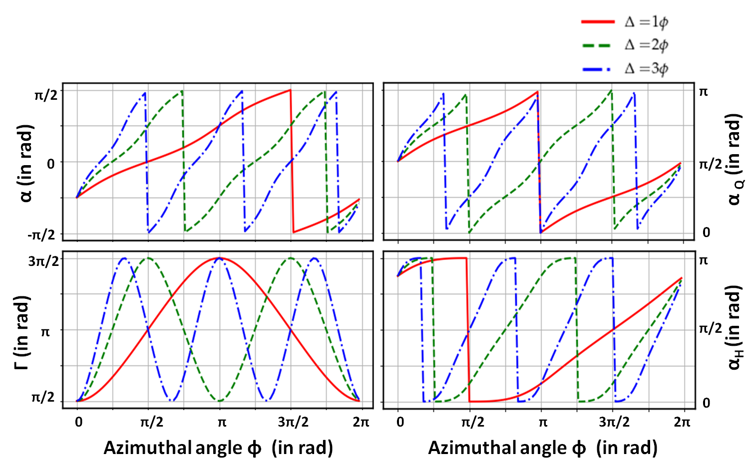
where . Figure (4) shows the azimuthal variation of and of the above equations, for and . The necessary fast axes variation of the QW-s-plates and HW-s-plates for realizing these using QHQ arrangement are also shown. The smooth azimuthal variation of and of the s-plates indicate the ease of their fabrication. The jumps observed in the fast-axis variations are always of magnitude and arise due to numerical inversion of Eq. (34). Since orientation of fast-axis is modulo , these jumps are experimentally inconsequential.
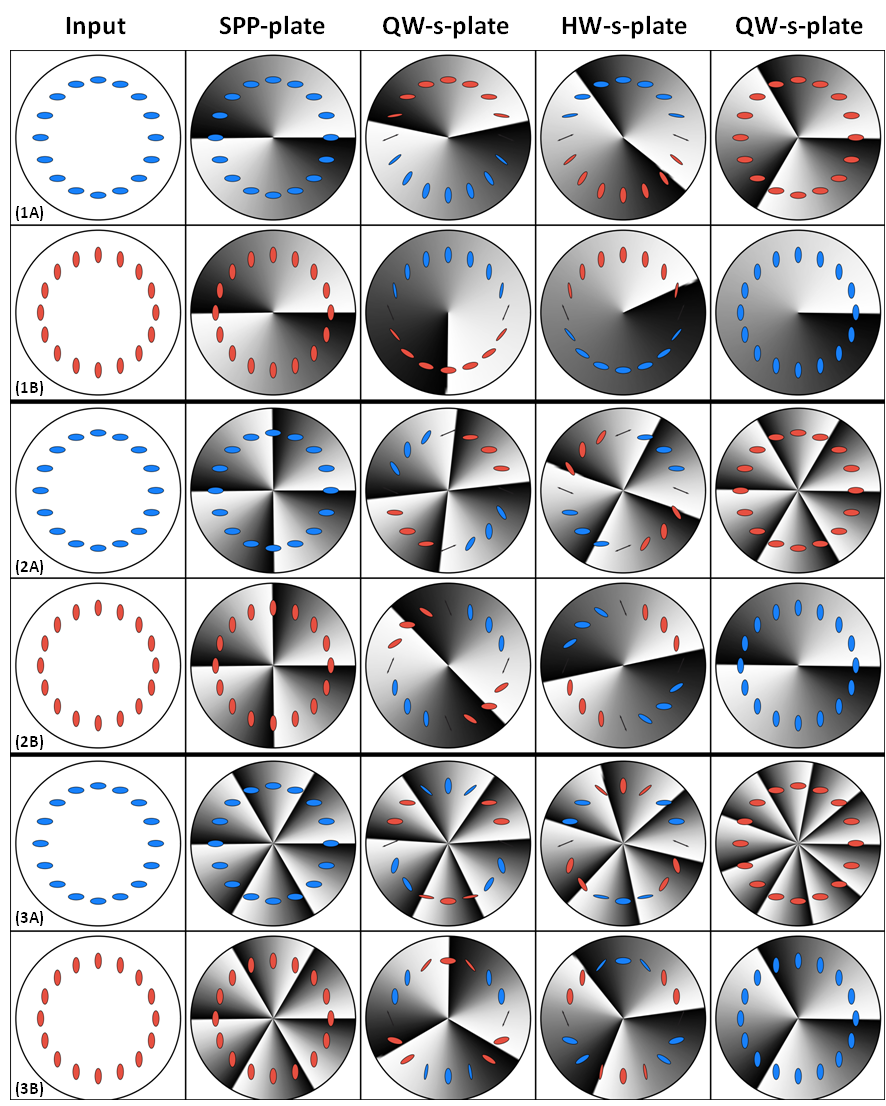
We now demonstrate the functioning of the QHQ arrangement towards realizing the J-plates. Figure (5) traces the simulated phase and polarization profile in the transverse plane of the light beam as it exits through each of the four plates (spiral phase plate and QHQ-s-plates). The input SoPs considered are and its orthogonal state, shown as rows (A) and (B) respectively. Rows (1), (2) and (3) correspond to the J-plates having , and respectively. These J-plates correspond to the d-plates of Fig. (4) together with the spiral phase plate of order , and respectively. In these figures, the polarization profile along the radial direction is uniform and hence is suppressed for visual clarity. The greyscale color coding depicts the phase in the transverse plane. In each of the six cases, even though the input scalar beam gets converted to vector beam in transit, the beam at the exit plane of the final plate is once again scalar but with the intended phase distribution. This demonstrates the utility of the QHQ-s-plates towards mimicking the J-plate.
To summarize this subsection, a generalized version of q-plates, for affecting polarization-dependent phase profile to the input light beam is mathematically elucidated through Eqs. (28 and 29). Parameters of the d-plate that assists this transformation are deduced in Eqs. (31 and 32). A simple, albeit non-trivial illustration of this idea has been demonstrated numerically in realizing the “J-plate” proposed recently in ref. (devlin2017arbitrary, ).
IV Summary and Conclusions
Optical elements which affect the polarization and phase of the light beam, without affecting its intensity belong to the class of “waveplates”. They are characterized by their retardance and orientation of fast-axis, and have been classified here into different kinds based on the spatial variation of these parameters. Waveplates exhibiting inhomogeneity in both their retardance and fast-axis orientation, referred to as d-plates here, have proved to be of immense utility in the recent years. The interplay of phase and polarization of the light, as it traverses through the d-plate, can be gainfully exploited towards realizing exotic structured light beams.
Fabrication of these d-plates, however, continues to be a formidable challenge, in contrast to singly inhomogeneous waveplates (s-plates), whose manufacture has been standardized in multiple ways. In this article a novel method for realizing “effective” d-plate involving only s-plates, has been proposed. This is achieved by establishing the equivalence of a d-plate and a gadget involving a HW-s-plate placed between two identically oriented QW-s-plates, using SU(2) formalism. Given a d-plate, -with an arbitrary spatial variation in both retardance and fast-axis orientation,- the necessary HW-s-plate and QW-s-plates for realizing it have been identified. An important advantage of this approach is that, using the same set of three s-plates, a variety of inequivalent d-plates can be realized by mere change of their relative orientations. The methodology is generic enough to be employed with any of the s-plate fabrication techniques. Further, the ability to dynamically tune the retardance of s-plates (for eg. with voltage controlled liquid-crystal based s-plates) allows for QHQ-s-plates to realize d-plates for different wavelengths.
The versatility and potential of this method has been exhibited in two steps: firstly, specific d-plates required for tailoring individual aspects of light have been identified. For each of these d-plates, the required s-plates have been identified and their equivalence with the d-plates has been analytically and numerically established.
Another significant contribution of this article has been in fashioning d-plates for (i) realizing an arbitrary complex field amplitude distribution and (ii) polarization-dependent phase manipulation.
In the first application, starting from a known electric field distribution, a generic polarimetric approach for realizing arbitrary complex electric field distribution has been presented. As a concrete example, LG beams and HG beams of higher order have been sculpted from the horizontally polarized fundamental Gaussian beam, using a specially designed d-plate and a polarizer. The ratio of input and output beam waists is seen to play an important role in deciding the conversion efficiency and needs to be optimized.
The second application presented here generalizes the functioning of q-plates. The phase-polarization interplay seen in waveplates has been exploited in designing a d-plate that functions like a polarization-dependent spatially varying phase plate. This d-plate imparts distinct phase distribution on the input light beam depending on its polarization.
The d-plates discussed here, although of significant interest in themselves, are not exhaustive but merely cursory pointing to their rich class. QHQ-s-plates offer an easy method of realizing any such d-plates, and we believe they will greatly advance the experimental state of the art in structuring of light and application involving structured light beams.
Appendix A Single effective waveplate.
The Jones matrices of HW-plate (retardance ) is given by (see Eq.(5))
and the Jones matrix of QW-plate (retardance ) is given by:
In QHQ arrangement, an HW-plate oriented at any angle say is sandwiched between two identically oriented QW-plates .
| (35) |
The resultant matrix of QHQ arrangement can be evaluated by making use of the Pauli-matrices identity namely: , given by:
| (36) |
The resultant matrix of QHQ arrangement, eq. (), is symmetric and has purely imaginary off-diagonal elements, similar to the Eq. (8). This arrangement is therefore equivalent to a single waveplate , whose effective retardance and an effective fast-axis orientation can be derived from Eqs. (9 and 10), and they are:
| (37) | ||||
| (38) |
Appendix B Rotating the waveplate
Consider a d-plate whose spatial variation in fast-axis orientation and retardance are respectively given by and . Mathematically, given the fast-axis orientation , the fast-axis in the X-Y plane is given by , where and are unit vectors along the and directions:
| (39) |
Now, consider rotating this plate by an angle, say . Because of this rotation, the field of vectors changes to . The rotated vectors in the old coordinates is given by
| (40) |
where is the rotation matrix about the -direction. Upon simplification, we have,
| (41) |
From which the fast-axis orientation after the rotation can be obtained as:
| (42) |
Retardance being a scalar, transforms simply as.
| (43) |
Appendix C Determining the Jones matrix
The Jones matrix of the unitary transformation in the basis is given by:
| (44) |
Given the unitary transformation of Eqs. (28 and 29), its action on can be identified by expressing them in the basis:
| (45) | ||||
| (46) |
Expressing and in the basis:
| (47) |
From this the determinant of the matrix is and this unitary matrix can be converted into a SU(2) matrix by multiplying with phase element as:
References
- (1) Shivaramakrishnan Pancharatnam. Generalized theory of interference and its applications. In Proceedings of the Indian Academy of Sciences-Section A, volume 44, pages 398–417. Springer, 1956.
- (2) Michael V Berry. The adiabatic phase and pancharatnam’s phase for polarized light. Journal of Modern Optics, 34(11):1401–1407, 1987.
- (3) Qiwen Zhan. Cylindrical vector beams: from mathematical concepts to applications. Advances in Optics and Photonics, 1(1):1–57, 2009.
- (4) Zhan Qiwen. Vectorial optical fields: Fundamentals and applications. World scientific, 2013.
- (5) Lorenzo Marrucci, C Manzo, and D Paparo. Optical spin-to-orbital angular momentum conversion in inhomogeneous anisotropic media. Physical review letters, 96(16):163905, 2006.
- (6) David L Andrews. Structured light and its applications: An introduction to phase-structured beams and nanoscale optical forces. Academic press, 2011.
- (7) Halina Rubinsztein-Dunlop, Andrew Forbes, Michael V Berry, Mark R Dennis, David L Andrews, Masud Mansuripur, Cornelia Denz, Christina Alpmann, Peter Banzer, Thomas Bauer, et al. Roadmap on structured light. Journal of Optics, 19(1):013001, 2016.
- (8) Carmelo Rosales-Guzmán, Bienvenu Ndagano, and Andrew Forbes. A review of complex vector light fields and their applications. Journal of Optics, 20(12):123001, 2018.
- (9) Ralf Dorn, Susanne Quabis, and Gerd Leuchs. Sharper focus for a radially polarized light beam. Physical review letters, 91(23):233901, 2003.
- (10) Les Allen, Marco W Beijersbergen, RJC Spreeuw, and JP Woerdman. Orbital angular momentum of light and the transformation of laguerre-gaussian laser modes. Physical Review A, 45(11):8185, 1992.
- (11) Yijie Shen, Xuejiao Wang, Zhenwei Xie, Changjun Min, Xing Fu, Qiang Liu, Mali Gong, and Xiaocong Yuan. Optical vortices 30 years on: Oam manipulation from topological charge to multiple singularities. Light: Science & Applications, 8(1):1–29, 2019.
- (12) K Yu Bliokh, FJ Rodríguez-Fortuño, Franco Nori, and Anatoly V Zayats. Spin–orbit interactions of light. Nature Photonics, 9(12):796, 2015.
- (13) Yachao Liu, Yougang Ke, Hailu Luo, and Shuangchun Wen. Photonic spin hall effect in metasurfaces: a brief review. Nanophotonics, 6(1):51–70, 2017.
- (14) Nir Shitrit, Igor Yulevich, Elhanan Maguid, Dror Ozeri, Dekel Veksler, Vladimir Kleiner, and Erez Hasman. Spin-optical metamaterial route to spin-controlled photonics. Science, 340(6133):724–726, 2013.
- (15) Andrea Aiello, Peter Banzer, Martin Neugebauer, and Gerd Leuchs. From transverse angular momentum to photonic wheels. Nature Photonics, 9(12):789–795, 2015.
- (16) Yuichi Kozawa and Shunichi Sato. Optical trapping of micrometer-sized dielectric particles by cylindrical vector beams. Optics Express, 18(10):10828–10833, 2010.
- (17) Brian J Roxworthy and Kimani C Toussaint Jr. Optical trapping with -phase cylindrical vector beams. New Journal of Physics, 12(7):073012, 2010.
- (18) Michael A Taylor, Muhammad Waleed, Alexander B Stilgoe, Halina Rubinsztein-Dunlop, and Warwick P Bowen. Enhanced optical trapping via structured scattering. Nature Photonics, 9(10):669–673, 2015.
- (19) Matthias Meier, Valerio Romano, and Thomas Feurer. Material processing with pulsed radially and azimuthally polarized laser radiation. Applied Physics A, 86(3):329–334, 2007.
- (20) Manuel Erhard, Robert Fickler, Mario Krenn, and Anton Zeilinger. Twisted photons: new quantum perspectives in high dimensions. Light: Science & Applications, 7(3):17146, 2018.
- (21) V.G. Chigrinov, V.M. Kozenkov, and H.S. Kwok. Photoalignment of Liquid Crystalline Materials: Physics and Applications. Wiley Series in Display Technology. Wiley, 2008.
- (22) Jihwan Kim, Yanming Li, Matthew N Miskiewicz, Chulwoo Oh, Michael W Kudenov, and Michael J Escuti. Fabrication of ideal geometric-phase holograms with arbitrary wavefronts. Optica, 2(11):958–964, 2015.
- (23) Wei Ji, Chun-Hong Lee, Peng Chen, Wei Hu, Yang Ming, Lijian Zhang, Tsung-Hsien Lin, Vladimir Chigrinov, and Yan-Qing Lu. Meta-q-plate for complex beam shaping. Scientific reports, 6:25528, 2016.
- (24) Dianmin Lin, Pengyu Fan, Erez Hasman, and Mark L Brongersma. Dielectric gradient metasurface optical elements. science, 345(6194):298–302, 2014.
- (25) Mohammadreza Khorasaninejad, Wei Ting Chen, Robert C Devlin, Jaewon Oh, Alexander Y Zhu, and Federico Capasso. Metalenses at visible wavelengths: Diffraction-limited focusing and subwavelength resolution imaging. Science, 352(6290):1190–1194, 2016.
- (26) Jacob Scheuer. Optical metasurfaces are coming of age: Short-and long-term opportunities for commercial applications. ACS Photonics, 2020.
- (27) Xiaohui Ling, Xinxing Zhou, Xunong Yi, Weixing Shu, Yachao Liu, Shizhen Chen, Hailu Luo, Shuangchun Wen, and Dianyuan Fan. Giant photonic spin hall effect in momentum space in a structured metamaterial with spatially varying birefringence. Light: Science & Applications, 4(5):e290–e290, 2015.
- (28) Mandira Pal, Chitram Banerjee, Shubham Chandel, Ankan Bag, Shovan K Majumder, and Nirmalya Ghosh. Tunable spin dependent beam shift by simultaneously tailoring geometric and dynamical phases of light in inhomogeneous anisotropic medium. Scientific reports, 6:39582, 2016.
- (29) Robert C Devlin, Antonio Ambrosio, Noah A Rubin, JP Balthasar Mueller, and Federico Capasso. Arbitrary spin-to–orbital angular momentum conversion of light. Science, 358(6365):896–901, 2017.
- (30) Mushegh Rafayelyan and Etienne Brasselet. Laguerre–gaussian modal q-plates. Optics letters, 42(10):1966–1969, 2017.
- (31) Noah A Rubin, Gabriele D’Aversa, Paul Chevalier, Zhujun Shi, Wei Ting Chen, and Federico Capasso. Matrix fourier optics enables a compact full-stokes polarization camera. Science, 365(6448):eaax1839, 2019.
- (32) Amir Arbabi, Yu Horie, Mahmood Bagheri, and Andrei Faraon. Dielectric metasurfaces for complete control of phase and polarization with subwavelength spatial resolution and high transmission. Nature nanotechnology, 10(11):937–943, 2015.
- (33) JP Balthasar Mueller, Noah A Rubin, Robert C Devlin, Benedikt Groever, and Federico Capasso. Metasurface polarization optics: independent phase control of arbitrary orthogonal states of polarization. Physical review letters, 118(11):113901, 2017.
- (34) Bruno Piccirillo, Vincenzo D Ambrosio, Sergei Slussarenko, Lorenzo Marrucci, and Enrico Santamato. Photon spin-to-orbital angular momentum conversion via an electrically tunable q-plate. Applied Physics Letters, 97(24):241104, 2010.
- (35) Sergei Slussarenko, Anatoli Murauski, Tao Du, Vladimir Chigrinov, Lorenzo Marrucci, and Enrico Santamato. Tunable liquid crystal q-plates with arbitrary topological charge. Opt. Express, 19(5):4085–4090, Feb 2011.
- (36) Ebrahim Karimi, Bruno Piccirillo, Eleonora Nagali, Lorenzo Marrucci, and Enrico Santamato. Efficient generation and sorting of orbital angular momentum eigenmodes of light by thermally tuned q-plates. Applied Physics Letters, 94(23):231124, 2009.
- (37) Shivaramakrishnan Pancharatnam. Achromatic combinations of birefringent plates part-i. In Proceedings of the Indian Academy of Sciences-Section A, volume 41, pages 130–136. Springer, 1955.
- (38) Shivaramakrishnan Pancharatnam. Achromatic combinations of birefringent plates part-ii. In Proceedings of the Indian Academy of Sciences-Section A, volume 41, pages 137–144. Springer, 1955.
- (39) Thorlabs super achromatic waveplates.
- (40) Xunong Yi, Ying Li, Xiaohui Ling, Yachao Liu, Yougang Ke, and Dianyuan Fan. Addition and subtraction operation of optical orbital angular momentum with dielectric metasurfaces. Optics Communications, 356:456–462, 2015.
- (41) Sam Delaney, María M Sánchez-López, Ignacio Moreno, and Jeffrey A Davis. Arithmetic with q-plates. Applied optics, 56(3):596–600, 2017.
- (42) B Radhakrishna, Gururaj Kadiri, and G Raghavan. Wavelength-adaptable effective q-plates with passively tunable retardance. Scientific reports, 9(1):1–9, 2019.
- (43) Olga Korotkova. Random light beams: theory and applications. CRC press, 2013.
- (44) Enrique J Galvez. Complex light beams. Deep Imaging in Tissue and Biomedical Materials: Using Linear and Nonlinear Optical Methods, page 31, 2017.
- (45) Zdeněk Bouchal. Nondiffracting optical beams: physical properties, experiments, and applications. Czechoslovak journal of physics, 53(7):537–578, 2003.
- (46) Michael Mazilu, D James Stevenson, Frank Gunn-Moore, and Kishan Dholakia. Light beats the spread:’non-diffracting’ beams. Laser & Photonics Reviews, 4(4):529–547, 2010.
- (47) Nikolaos K Efremidis, Zhigang Chen, Mordechai Segev, and Demetrios N Christodoulides. Airy beams and accelerating waves: an overview of recent advances. Optica, 6(5):686–701, 2019.
- (48) Massimo Granata, Christelle Buy, Robert Ward, and Matteo Barsuglia. Higher-order laguerre-gauss mode generation and interferometry for gravitational wave detectors. Physical review letters, 105(23):231102, 2010.
- (49) Liu Tao, Anna Green, and Paul Fulda. Higher-order hermite-gauss modes as a robust flat beam in interferometric gravitational wave detectors. arXiv preprint arXiv:2010.04338, 2020.
- (50) Stefan W Hell and Jan Wichmann. Breaking the diffraction resolution limit by stimulated emission: stimulated-emission-depletion fluorescence microscopy. Optics letters, 19(11):780–782, 1994.
- (51) Wentao Yu, Ziheng Ji, Dashan Dong, Xusan Yang, Yunfeng Xiao, Qihuang Gong, Peng Xi, and Kebin Shi. Super-resolution deep imaging with hollow bessel beam sted microscopy. Laser & Photonics Reviews, 10(1):147–152, 2016.
- (52) NB Simpson, L Allen, and MJ Padgett. Optical tweezers and optical spanners with laguerre–gaussian modes. Journal of modern optics, 43(12):2485–2491, 1996.
- (53) NB Simpson, K Dholakia, L Allen, and MJ Padgett. Mechanical equivalence of spin and orbital angular momentum of light: an optical spanner. Optics letters, 22(1):52–54, 1997.
- (54) EM Wright, J Arlt, and K Dholakia. Toroidal optical dipole traps for atomic bose-einstein condensates using laguerre-gaussian beams. Physical Review A, 63(1):013608, 2000.
- (55) Mushegh Rafayelyan, Titas Gertus, and Etienne Brasselet. Laguerre-gaussian quasi-modal q-plates from nanostructured glasses. Applied Physics Letters, 110(26):261108, 2017.
- (56) Jay N Damask. Polarization optics in telecommunications, volume 101. Springer Science & Business Media, 2004.
- (57) Radhakrishna Bettegowda. Prescription for transforming polarization states of light using two-quarter waveplates. Optical Engineering, 56(3):034110, 2017.
- (58) Karol Salazar-Ariza and Rafael Torres. Trajectories on the poincaré sphere of polarization states of a beam passing through a rotating linear retarder. JOSA A, 35(1):65–72, 2018.
- (59) R Simon and N Mukunda. Universal su (2) gadget for polarization optics. Physics Letters A, 138(9):474–480, 1989.
- (60) Rajendra Bhandari. Polarization of light and topological phases. Physics Reports, 281(1):1–64, 1997.
- (61) MW Beijersbergen, RPC Coerwinkel, M Kristensen, and JP Woerdman. Helical-wavefront laser beams produced with a spiral phaseplate. Optics Communications, 112(5-6):321–327, 1994.