Planar-integrated magneto-optical trap
Abstract
The magneto-optical trap (MOT) is an essential tool for collecting and preparing cold atoms with a wide range of applications. We demonstrate a planar-integrated MOT by combining an optical grating chip with a magnetic coil chip. The flat grating chip simplifies the conventional six-beam configuration down to a single laser beam; the flat coil chip replaces the conventional anti-Helmholtz coils of a cylindrical geometry. We trap cold atoms in the planar-integrated MOT, at a point 3 – 9 mm above the chip surface. This novel configuration effectively reduces the volume, weight, and complexity of the MOT, bringing benefits to applications including gravimeter, clock and quantum memory devices.
I Introduction
The magneto-optical trap (MOT) is one of the most important experimental platforms in atomic physics (Zhai, 2015; Firstenberg et al., 2016; Cooper et al., 2019; Tomza et al., 2019). Cold atoms prepared by a MOT are widely used in quantum measurement and metrology applications (Liu et al., 2018; Grotti et al., 2018; Udem et al., 2002). For example, the atomic gravimetry with precision achieving Gal/ has been demonstrated (Hu et al., 2013). The conventional MOT apparatus consists of three orthogonal pairs of retro-reflected laser beams and a pair of anti-Helmholtz coils in a cylindrical geometry (Raab et al., 1987).
Over the past decade, great efforts have been devoted to minimizing the MOT system. Most attentions are paid to reducing the bulky optical system. For example, by using a pyramidal retroreflector, only one incident laser beam is needed (Lee et al., 1996; Vangeleyn et al., 2009; Pollock et al., 2009, 2011). More recently, the idea was further developed by replacing the pyramidal retroreflector with a completely flat chip consisting of three gratings, demonstrating a MOT that can capture as many as atoms with a single incident laser beam (Vangeleyn et al., 2010; Nshii et al., 2013; Lee et al., 2013; McGilligan et al., 2016; Cotter et al., 2016). In contrast, the original bulky anti-Helmholtz coils still remain. Although U- or Z-shaped wires were employed in an atom chip to assist the MOT, external Helmholtz coils were still required to provide a bias field (Reichel et al., 1999; Denschlag et al., 1999; Folman et al., 2000; Pollock et al., 2009, 2011; Rushton et al., 2016).
In this work, we develop a planar-integrated MOT (piMOT) configuration based on both a grating chip and a planar coil chip. The coil chip generates a quadrupole magnetic field several millimeters above the chip surface, matching the working points of the optical grating chip. While carrying a current of , the magnetic field gradient reaches , and the low working voltage of and power of allows it to be powered by batteries. With both chips stacked outside a glass vacuum cell, we trap atoms. The piMOT is simple, portable, and low-cost. It opens the possibility for further monolithic integration of the cold atom system with photonic chips (Xie et al., 2019; Hu et al., 2020; Wang et al., 2021; McGehee et al., 2021), with future applications including portable gravimeter (Kasevich and Chu, 1991; Peters et al., 1999, 2001; Wang et al., 2018), clock (ESSEN and PARRY, 1955; de Beauvoir et al., 1997; Laurent et al., 2006; Liu et al., 2017a, b) and quantum memory devices (Duan et al., 2001; Ding et al., 2015; Wang et al., 2019; Wen et al., 2019).
II The coil chip
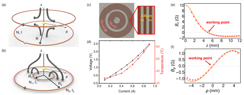
The atoms are trapped in the MOT at the working point where the field equals zero and strong field gradients are present in all directions (Bergeman et al., 1987). A conventional MOT generates this magnetic field using a pair of anti-Helmholtz coils (Raab et al., 1987), which is composed by a pair of identical coils (same radius , current , and turns ) with opposite current directions, as shown in Fig. 1(a). The working point of this coil configuration is exactly its geometrical center. This cylindrical geometry poses limitations on a compact cold-atom system. For example, the vacuum cell needs to be inserted in between the pair of coils, thus limiting the minimum size of the coils. In order to reach the required ~ 10 G/cm field gradient, the required currents in the coils grow with the cube of the coil size, which then leads to heat dissipation problems. These limitations can be overcome with a planar coil design to achieve a compact system.
We propose the coplanar annular coil chip [Fig. 1(b)], consisting of two coaxial coils with different radii and (), different numbers of turns and , and opposite currents and - (). Here, we define the center of the coils as the origin of the circular coordinate system and the axis perpendicular to the coil plane. At a point () on the axis, the coils produce a magnetic field intensity as (Bergeman et al., 1987)
| (1) |
| (2) |
and the corresponding magnetic field gradients
| (3) | ||||
| (4) |
Due to the cylindrical symmetry, on the -axis. For simplicity, we first consider the case of balanced currents , which allows the two coils to be connected in series with one current supply. For appropriate and , we can adjust and to make the field intensities zero at a desired height , i.e. at the target MOT working point . As a result, this coplanar coil configuration is able to provide the quadrupole magnetic field for realizing MOT, with a working point above the surface of the coil plane.
A coil chip is constructed based on the printed-circuit-board (PCB) technology, with a chip thickness of and an edge length of . The coils are made by copper wire printed on a square Rogers ceramic substrate [Fig. 1(c)]. The thickness, width, and spacing of the wire are , , and , respectively. The inner coil has turns, with a radius ranging from 2.6 mm to 7.8 mm, and the outer coil has turns, with a radius ranging from 9.6 mm to 14.8 mm. According to Eq. (1-4), this coil chip has a working point at the height , an axial field gradient of and a radial gradient of when carrying a current of .
Figures 1(e) and (f) show the calculation and measurement results of the axial and radial magnetic fields ( and ). As designed, the coil chip provides an axial gradient of and a radial gradient of around the working point with . From the measured field distribution, in a range of about along both and directions around the working point, the coil chip can provide the desired magnetic field gradients for the MOT. This provides a sufficiently large volume for confining cold atoms.
Besides the magnetic fields, we also evaluate the performance of the coil chip for practical applications by measuring the steady-state voltage and temperature of the chip versus the current [Fig. 1(d)]. The coil chip is placed in an ambient environment underneath the glass cell. At the working current I = 0.9 A, the voltage is measured to be 2.5 V, corresponding to a resistive heating power of 2.2 W. The chip temperature remains at around . For application without need for modulation, the coil chip can be replaced by a ring of permanent magnet to remove the power supply and avoid heating issue. In conclusion, the coil chip can provide a stable magnetic field for MOT at a low power setting. This is made possible by the small distances in the planar integration design.
III Experimental performance of the planar-integrated MOT
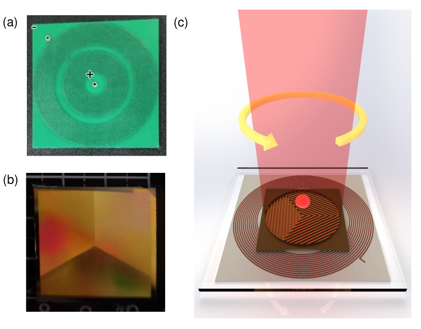
Figure 2(c) shows a conceptual sketch of the co-integrated MOT based on the combination of a grating chip [Fig. 2(b)] and a coil chip [Fig. 2(a)]. The grating chip consists of three etched gratings on a silicon substrate. Following the pioneering works of the grating MOT (Nshii et al., 2013; Cotter et al., 2016), the angle between grating periodic directions is , and the grating period and duty cycle are and , respectively. The top side of the grating chip is gold-coated to increase diffraction efficiency. The measured diffraction angle is with respect to -axis and the diffraction efficiency is .
In our experiment, the grating chip is mounted underneath and outside the vacuum cell. The coil chip is mounted below the grating chip and aligned so that the two working points of the chips coincide. Two ECDL diode lasers are tuned to the D2 lines. The cooling laser frequency is tuned to the to cycling transition with a detuning , and the repump laser is tuned to the to transition. The beams of the two lasers are combined and coupled into a polarization maintaining fiber and delivered to the MOT setup. The incident beam is circularly polarized, has a diameter of , an optical intensity of for the cooling laser and for the repump. Three first-order diffraction beams from the gratings along with the incident beam form a MOT in the presence of a quadrupole magnetic field [see Fig. 2(a)].
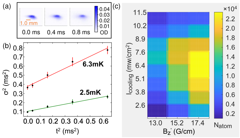
By absorption imaging and time-of-flight method, the temperature of the trapped atom cloud is evaluated. Figure 3(a) shows the absorption images of cold atoms following free expansion over a duration . Figure. 3(b) shows the experimental and fitting results of the atom cloud sizes against . The extracted temperature is for the axial direction and for the radial direction. Moreover, we adjust the cooling laser intensity and the magnetic field gradient to examine the system performance, and the results are summarized in Fig. 3(c). At a trapping laser intensity of , the planar-integrated MOT achieves an atom number of and a number density of .
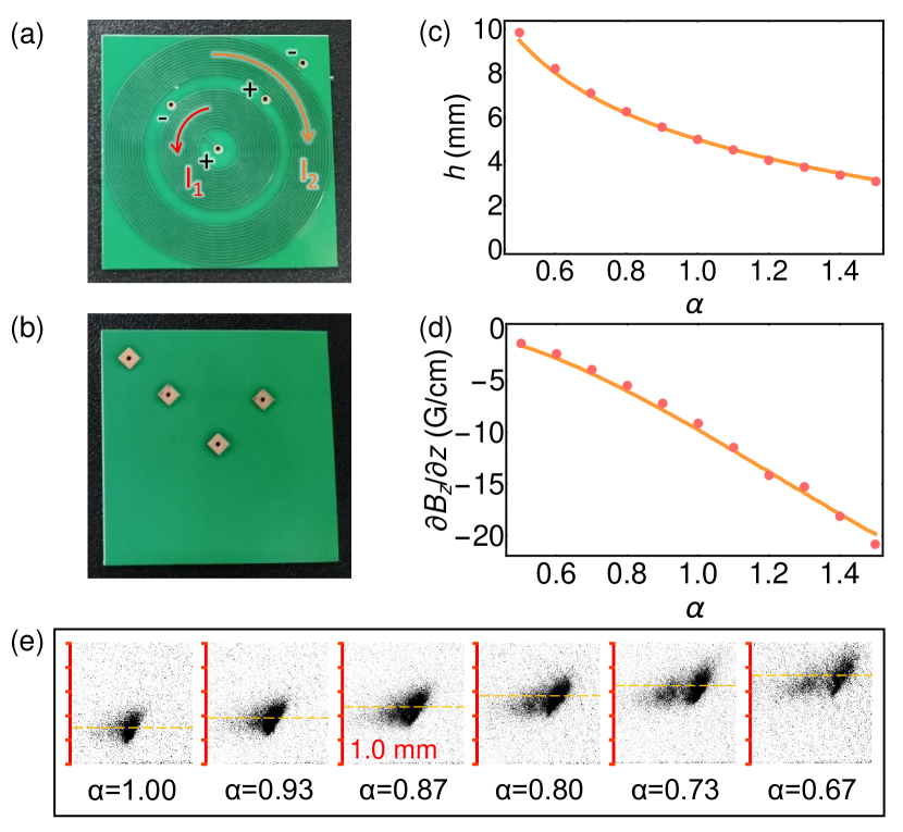
According to Eq. (1) and Eq. (3), the working point moves vertically when adjusting the ratio of the currents in two planar spirals . The orange lines in Figs. 4(c) and (d) show the simulation results of the height of working point and the gradient , with ranges from to and is fixed. We find that the varies from to , with the field gradient varying from to . To verify this result, we modified the coil chip with two sets of printed pads to individually supply the currents for inner and outer coils. The experimental results (red dots) in Figs. 4(c) and (d) fit well with the theoretical predictions. Then, with such a modified coil chip, we realized the adjusting of the atom cloud height from to by varying from to , as shown by Fig. 4(e). These results indicate a wide tunability of the working point for the planar-integrated MOT with future monolithic integration of the grating and coils.
IV Conclusion
In conclusion, we have demonstrated a planar coil configuration to provide a quadrupole magnetic field for realizing a chip-based MOT. Combining two chips, for coil and grating, the planar-integrated MOT is realized for the first time, with significantly reduced volume and weight. This configuration allows more optical access and reduces the power requirements on the current supply and heat dissipation. The planar-integrated MOT also shows excellent compatibility with photonic chips and convenience in alignments, providing an important solution towards a fullyintegrated cold-atom system for sensors and quantum devices.
Acknowledgments
We would like to thank Tianchu
Li, Yang Yang and Xiaochi Liu for helpful discussions. The work was
supported by the National Key Research and Development Program of
China (Grant Nos. 2016YFA0302200 and 2016YFA0301303), the National
Natural Science Foundation of China (Grant Nos. 11922411, 11874342,
and 41727901), Anhui Initiative in Quantum Information Technologies
(Grant No. AHY130200), and the Fundamental Research Funds for the
Central Universities (Grant No. WK2470000031). This work was partially
carried out at the USTC Center for Micro and Nanoscale Research and
Fabrication.
References
- Zhai (2015) H. Zhai, Reports on Progress in Physics 78, 026001 (2015).
- Firstenberg et al. (2016) O. Firstenberg, C. S. Adams, and S. Hofferberth, Journal of Physics B: Atomic, Molecular and Optical Physics 49, 152003 (2016), arXiv:1602.06117 .
- Cooper et al. (2019) N. R. Cooper, J. Dalibard, and I. B. Spielman, Reviews of Modern Physics 91, 015005 (2019), arXiv:1803.00249 .
- Tomza et al. (2019) M. Tomza, K. Jachymski, R. Gerritsma, A. Negretti, T. Calarco, Z. Idziaszek, and P. S. Julienne, Reviews of Modern Physics 91, 035001 (2019), arXiv:1708.07832 .
- Liu et al. (2018) L. Liu, D.-S. Lü, W.-B. Chen, T. Li, Q.-Z. Qu, B. Wang, L. Li, W. Ren, Z.-R. Dong, J.-B. Zhao, W.-B. Xia, X. Zhao, J.-W. Ji, M.-F. Ye, Y.-G. Sun, Y.-Y. Yao, D. Song, Z.-G. Liang, S.-J. Hu, D.-H. Yu, X. Hou, W. Shi, H.-G. Zang, J.-F. Xiang, X.-K. Peng, and Y.-Z. Wang, Nature Communications 9, 2760 (2018).
- Grotti et al. (2018) J. Grotti, S. Koller, S. Vogt, S. Häfner, U. Sterr, C. Lisdat, H. Denker, C. Voigt, L. Timmen, A. Rolland, F. N. Baynes, H. S. Margolis, M. Zampaolo, P. Thoumany, M. Pizzocaro, B. Rauf, F. Bregolin, A. Tampellini, P. Barbieri, M. Zucco, G. A. Costanzo, C. Clivati, F. Levi, and D. Calonico, Nature Physics 14, 437 (2018), arXiv:1705.04089 .
- Udem et al. (2002) T. Udem, R. Holzwarth, and T. W. Hänsch, Nature 416, 233 (2002).
- Hu et al. (2013) Z.-K. Hu, B.-L. Sun, X.-C. Duan, M.-K. Zhou, L.-L. Chen, S. Zhan, Q.-Z. Zhang, and J. Luo, Physical Review A 88, 043610 (2013).
- Raab et al. (1987) E. L. Raab, M. Prentiss, A. Cable, S. Chu, and D. E. Pritchard, Physical Review Letters 59, 2631 (1987).
- Lee et al. (1996) K. I. Lee, J. A. Kim, H. R. Noh, and W. Jhe, Optics Letters 21, 1177 (1996).
- Vangeleyn et al. (2009) M. Vangeleyn, P. F. Griffin, E. Riis, and A. S. Arnold, Optics Express 17, 13601 (2009), arXiv:0905.2897 .
- Pollock et al. (2009) S. Pollock, J. P. Cotter, A. Laliotis, and E. A. Hinds, Optics Express 17, 14109 (2009).
- Pollock et al. (2011) S. Pollock, J. P. Cotter, A. Laliotis, F. Ramirez-Martinez, and E. A. Hinds, New Journal of Physics 13, 043029 (2011), arXiv:1101.0686 .
- Vangeleyn et al. (2010) M. Vangeleyn, P. F. Griffin, E. Riis, and A. S. Arnold, Optics Letters 35, 3453 (2010), arXiv:1006.4526 .
- Nshii et al. (2013) C. C. Nshii, M. Vangeleyn, J. P. Cotter, P. F. Griffin, E. A. Hinds, C. N. Ironside, P. See, A. G. Sinclair, E. Riis, and A. S. Arnold, Nature Nanotechnology 8, 321 (2013), arXiv:1311.1011 .
- Lee et al. (2013) J. Lee, J. A. Grover, L. A. Orozco, and S. L. Rolston, Journal of the Optical Society of America B 30, 2869 (2013), arXiv:1309.4732 .
- McGilligan et al. (2016) J. P. McGilligan, P. F. Griffin, E. Riis, and A. S. Arnold, Journal of the Optical Society of America B 33, 1271 (2016), arXiv:1601.07431 .
- Cotter et al. (2016) J. P. Cotter, J. P. McGilligan, P. F. Griffin, I. M. Rabey, K. Docherty, E. Riis, A. S. Arnold, and E. A. Hinds, Applied Physics B 122, 172 (2016), arXiv:1601.05548 .
- Reichel et al. (1999) J. Reichel, W. Hänsel, and T. W. Hänsch, Physical Review Letters 83, 3398 (1999).
- Denschlag et al. (1999) J. Denschlag, D. Cassettari, and J. Schmiedmayer, Physical Review Letters 82, 2014 (1999).
- Folman et al. (2000) R. Folman, P. Krüger, D. Cassettari, B. Hessmo, T. Maier, and J. Schmiedmayer, Physical Review Letters 84, 4749 (2000).
- Rushton et al. (2016) J. Rushton, R. Roy, J. Bateman, and M. Himsworth, New Journal of Physics 18, 113020 (2016), arXiv:1607.08662 .
- Xie et al. (2019) J. Xie, J.-Q. Wang, Z.-B. Wang, X.-X. Hu, X. Guo, R. Niu, J. B. Surya, J.-Z. Zhang, C.-H. Dong, G.-C. Guo, H. X. Tang, and C.-L. Zou, Opt. Lett. 44, 1150 (2019), arXiv:1901.00922 .
- Hu et al. (2020) X.-X. Hu, J.-Q. Wang, Y.-H. Yang, J. B. Surya, Y.-L. Zhang, X.-B. Xu, M. Li, C.-H. Dong, G.-C. Guo, H. X. Tang, and C.-L. Zou, Opt. Express 28, 11144 (2020).
- Wang et al. (2021) J.-Q. Wang, Y.-H. Yang, M. Li, X.-X. Hu, J. B. Surya, X.-B. Xu, C.-H. Dong, G.-C. Guo, H. X. Tang, and C.-L. Zou, Physical Review Letters 126, 133601 (2021), arXiv:2011.10352 .
- McGehee et al. (2021) W. R. McGehee, W. Zhu, D. S. Barker, D. Westly, A. Yulaev, N. Klimov, A. Agrawal, S. Eckel, V. Aksyuk, and J. J. McClelland, New Journal of Physics 23, 013021 (2021).
- Kasevich and Chu (1991) M. Kasevich and S. Chu, Physical Review Letters 67, 181 (1991).
- Peters et al. (1999) A. Peters, K. Y. Chung, and S. Chu, Nature 400, 849 (1999).
- Peters et al. (2001) A. Peters, K. Y. Chung, and S. Chu, Metrologia 38, 25 (2001).
- Wang et al. (2018) S.-K. Wang, Y. Zhao, W. Zhuang, T.-C. Li, S.-Q. Wu, J.-Y. Feng, and C.-J. Li, Metrologia 55, 360 (2018).
- ESSEN and PARRY (1955) L. ESSEN and J. V. L. PARRY, Nature 176, 280 (1955).
- de Beauvoir et al. (1997) B. de Beauvoir, F. Nez, L. Julien, B. Cagnac, F. Biraben, D. Touahri, L. Hilico, O. Acef, A. Clairon, and J. J. Zondy, Physical Review Letters 78, 440 (1997).
- Laurent et al. (2006) P. Laurent, M. Abgrall, C. Jentsch, P. Lemonde, G. Santarelli, A. Clairon, I. Maksimovic, S. Bize, C. Salomon, D. Blonde, J. Vega, O. Grosjean, F. Picard, M. Saccoccio, M. Chaubet, N. Ladiette, L. Guillet, I. Zenone, C. Delaroche, and C. Sirmain, Applied Physics B 84, 683 (2006).
- Liu et al. (2017a) X. Liu, V. I. Yudin, A. V. Taichenachev, J. Kitching, and E. A. Donley, Applied Physics Letters 111, 224102 (2017a).
- Liu et al. (2017b) X. Liu, E. Ivanov, V. I. Yudin, J. Kitching, and E. A. Donley, Physical Review Applied 8, 054001 (2017b).
- Duan et al. (2001) L.-M. Duan, M. D. Lukin, J. I. Cirac, and P. Zoller, Nature 414, 413 (2001), arXiv:0105105 [quant-ph] .
- Ding et al. (2015) D.-S. Ding, W. Zhang, Z.-Y. Zhou, S. Shi, G.-Y. Xiang, X.-S. Wang, Y.-K. Jiang, B.-S. Shi, and G.-C. Guo, Physical Review Letters 114, 050502 (2015), arXiv:1404.0439 .
- Wang et al. (2019) Y. Wang, J. Li, S. Zhang, K. Su, Y. Zhou, K. Liao, S. Du, H. Yan, and S.-L. Zhu, Nature Photonics 13, 346 (2019), arXiv:2004.03123 .
- Wen et al. (2019) R. Wen, C.-L. Zou, X. Zhu, P. Chen, Z. Y. Ou, J. F. Chen, and W. Zhang, Physical Review Letters 122, 253602 (2019), arXiv:1811.00307 .
- Bergeman et al. (1987) T. Bergeman, G. Erez, and H. J. Metcalf, Physical Review A 35, 1535 (1987).