Collective hydrodynamic transport of magnetic microrollers†
Gaspard Junot,a Andrejs Cebers,b and Pietro Tiernoacd
Received Xth XXXXXXXXXX 20XX, Accepted Xth XXXXXXXXX 20XX
First published on the web Xth XXXXXXXXXX 200X
DOI: xxxxx
We investigate the collective transport properties of microscopic magnetic rollers that propel close to a surface due to a circularly polarized, rotating magnetic field. The applied field exerts a torque to the particles, which induces a net rolling motion close to a surface. The collective dynamics of the particles result from the balance between magnetic dipolar interactions and hydrodynamic ones. We show that, when hydrodynamics dominate, i.e. for high particle spinning, the collective mean velocity linearly increases with the particle density. In this regime we analyse the clustering kinetics, and find that hydrodynamic interactions between the anisotropic, elongated particles, induce preferential cluster growth along a direction perpendicular to the driving one, leading to dynamic clusters that easily break and reform during propulsion.
1 Introduction
††footnotetext: † Electronic Supplementary Information (ESI) available: Three .WMV videos showing the dynamics of the hematite microroller at different frequencies. See DOI: xxxx/b000000x/††footnotetext: a Departament de Física de la Matèria Condensada, Universitat de Barcelona, Barcelona, Spain E-mail: ptierno@ub.edu††footnotetext: b MMML Lab, Department of Physics, University of Latvia, Jelgavas-3, Riga, LV-1004, Latvia.††footnotetext: c Universitat de Barcelona Institute of Complex Systems (UBICS), Universitat de Barcelona, Barcelona, Spain††footnotetext: d Institut de Nanociència i Nanotecnologia, Universitat de Barcelona, 08028, Barcelona, Spain.Microscopic surface rotors driven by a time-dependent magnetic field, represent a versatile and simple, yet non trivial, model system to investigate emergent collective phenomena, 1, 2, 3, 4 similar to those observed in ensemble of active and self-propelling particles. 5, 6 An external, time-dependent field is used to apply a magnetic torque to the particles, and to induce a net spinning close to a substrate. 7, 8, 9, 10, 11, 12, 13, 14, 15 Since these particles have size within the micrometer range and speed of the order of few (similar to that of bacteria or cells), their dynamics occur at effectively low Reynolds number (). Under these conditions, inertia is negligible and Navier-Stokes equations become time-reversible. 16 In this situation propulsion is possible only when the motion is non-reciprocal, namely based on a sequence of body/shape changes that are not identical when reversed in time. 17 Rotating helical flagella in bacteria, 18, 19 flexibility in the tail 20, 21 or chemical reactions, 22, 23 represent some ways to circumvent this constraint. In contrast, surface rollers present a relative simple mechanism of motion, based on the rotational/translational coupling with a close substrate. 24 Moreover, magnetic dipolar forces between the microrollers can be tuned by an external field, a feature that allows to investigate the role of such forces in the organization process and their interplay with other interactions such as hydrodynamic ones.
In this context, some of us recently investigate the dynamics of pair of propelling microrollers composed of anisotropic hematite particles that are driven close to a plane by an external rotating magnetic field. 25, 26 In such system, hydrodynamic interactions (HIs) between the particles induce the formation of stable bound states, where the particles align tip to tip, namely with their relative position parallel to the long axis, even if dipolar forces are repulsive in this configuration. However, the collective effects generated by several interacting microrollers and how the produced flow field alters the global mean velocity remain still unclear.
In this article we investigate the collective dynamics of interacting microrollers, and show that the average translational speed linearly raises with density. A similar behaviour was recently reported with different magnetic particles rolling close to a surface 47, a fact that enforces its generic nature. For our system, this feature cannot be explained by considering only dipolar forces. Furthermore, this speed up effect can be controlled by tuning the driving frequency which set the strength of the hydrodynamic interactions. We rationalize this observation by calculating the flow field generated by a set of rotating point particles. Further, we analyse the clustering process, and show that HIs lead to the formation of dynamic clusters which preferentially grow perpendicular to the propulsion direction.
2 Experimental details
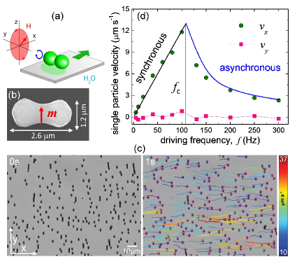
As shown in Fig.1, our magnetic microrollers are monodisperse hematite particles with a peanut-like shape. This shape results from the particular fabrication process, more details can be found in a previous work. 25 From the analysis of images obtained with scanning electron microscopy, as shown in the inset in Fig.1(b), we find that the hematite particles are characterized by two connected lobes with a long (short) axis equal to (). The hematite particles present a small permanent dipole moment oriented perpendicular to their long axis. This feature can be explained by considering the magnetic structure of hematite, that crystallizes in the corundum form, where Fe cations are aligned antiferromagnetically. 27, 28 The magnetic moment of the hematite ellipsoids was previously determined by measuring the particle relaxation under a static field, 29 and is of the order .
After synthesis, the particles are dispersed in pure water (Milli-Q system, Millipore), with sodium dodecyl sulfate (SDS) at a concentration , and let sediment above a plastic petridish. The SDS gives a steric layer to the particles which avoids irreversible particle sticking due to attractive Van der Waals interaction. Further, we raise the pH of the solution between and by adding Tetramethylammonium Hydroxide. The particles remain confined close to the plate due to gravity, where they float at a distance there.
The system dynamics are visualized using a light microscope (Eclipse Ni, Nikon) equipped with a CCD camera (Scout scA640-74f, Basler). Further, we apply the external magnetic fields using a set of custom-made magnetic coils mounted directly on the microscope stage. The rotating field in the plane is obtained by connecting two set of coils to a wave generator (TTi-TGA1244, TTi) feeding a power amplifier (IMG STA-800, stage line).
3 Microroller propulsion
To propel the hematite particles we use a rotating magnetic field circularly polarized in the plane, , being the amplitude and the driving frequency, see Fig.1(a). As an example, in Fig.1(c) we show two microscope snapshots of a collection of hematite rollers that are driven toward right by a rotating field with frequency Hz, reaching an average translational speed . We indicate with , the single particle velocities in the plane , and with the collective speed, where . As the magnetic moments in each particle are directed along their short axis, the particles roll around their long axis. Since we are interested in the collective particle transport, in this work we keep fix the field amplitude to , and vary mainly the driving frequency and the particle density , being the number of particles in the observation region . Further, we note that above the magnetic rollers start to overlap and propel also in the third dimension. This situation complicates the particle tracking, thus we limit our measurements to lower particle densities.
Before exploring the collective transport, we start by showing in Fig.1(d) how the single particle speed changes with . For a rotating field polarized in the plane, the hematite particles display a negligible transverse velocity () while the translational motion along the -axis can be characterized by two dynamic regimes. Below a critical frequency Hz, the magnetic moment of the particle follows the applied field. In this synchronous regime the particle rotational spinning coincides with the driving one, and the rolling velocity is where , and is a prefactor that takes into account the close proximity of the wall. The continuous blue line in Fig.1(d) shows the corresponding fit to the experimental data in this linear regime, where we get . In contrast, for the motion becomes asynchronous, and this produces a reduction of the translational speed which can be described as , 30, 31 as shown by the continuous blue line in Fig.1(d). We note that, given the large density of the hematite particles ( in the bulk), some rollers may become close to the surface especially at low spinning frequencies ( and ), when the hydrodynamic flow generated by the spinning is low. In such cases, there can be some effects due to surface friction. We discuss the role of the different forces acting on the single propelling rotor in the Appendix of the manuscript.
4 Collective transport.
At large density, the hematite rollers start to interact due to their magnetic moments and the generated hydrodynamic flow. In agreement with previous observations for pair of particles, 25 we find that close to the HIs dominate over magnetic one, and the particle preferentially assemble tip to tip. In this configuration magnetic dipolar interactions are repulsive, since the hematite moments rotate along parallel planes. This effect can be quantified if one consider the magnetic dipolar interaction between a pair of particles , at positions and and with moments and . Assuming point like particles, this interaction reads
| (1) |
were is the magnetic susceptibility of the medium (water), and the separation distance. Eq.1 shows that is maximally attractive (repulsive) for particles with magnetic moments parallel (perpendicular) to . If one perform a time averaging, it is straightforward to show that hematite particles rolling side by side are effectively attractive with . In contrast, when the particles are aligned tip to tip on the same plane, the moments are always perpendicular to their separation distance, and is repulsive, .
From the experimental observations, we find that at low frequency Hz, the particles tend usually to form compact clusters that grow along the propulsion direction, thus favouring chaining due to attractive dipolar force, see VideoS1 in the Supporting Information. However, for higher frequency these clusters form and break preferentially along the perpendicular direction, and thus their formation is promoted by HIs, being repulsive, see VideoS2.
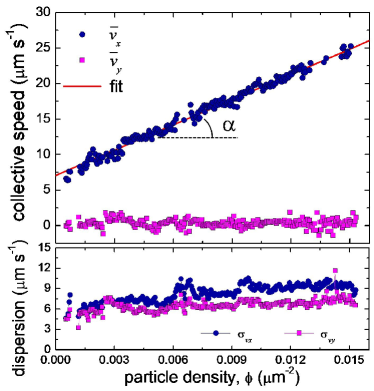
We now focus on the collective velocity as function of the particle density. As shown in Fig. 2, linearly raises with the particle density , while being negligible the transverse velocity. The fluctuations in speed also increase with along both directions. At high frequencies, when HIs dominates, we find that such interactions induce the formations of fragile clusters which grow perpendicular to the propulsion directions, see supporting videos. These clusters continuously break and reform, and this effect induces a raise of the speed fluctuations along the propulsion directions due to their fragmentation process, and perpendicular to it due to their anisotropic growth.
We explain this collective speed up effect by considering only HIs and taking into account the proximity of the wall. We assume an homogeneous distribution of point like particles with density , each subjected to a magnetic torque . For a single particle at position above a no-slip surface at , the translational velocity is given by
| (2) |
where . The velocity field created by the ensemble of rollers is obtained as:
Carrying out this integration gives rise to a discontinuous velocity profile for and for . The obtained relationship shows that effectively the particle speed grows proportionally to the density of rollers in a two dimensional plane. We note that such density dependence was shown to give rise to the Burger equation for the particle concentration. 32
To apply this result to our hematite rollers, we derive the translational speed of the single particle subjected to the magnetic torque . According to Ref.24, the linear and angular velocities of a force-free spherical particle near a solid wall under an external torque must satisfy the conditions
| (3) |
and
| (4) |
where we consider the following friction coefficients approximating rotating particles by spheres: 24
Here characterizes the thickness of the liquid layer between the particle and the no-slip surface. Eqs. (3,4) give
| (6) |
and
| (7) |
We use Eq.7 to fit the experimental data in Fig.2, where we keep as sole variable the particle elevation from the surface. From the linear regression we determine the elevation from the centre of the particle to the plane. Since the hematite particles roll perpendicular to their long axis, we obtain that the surface to surface elevation is given by nm, a reasonable value similar to that found in previous works with other magnetic colloids floating close to a plane in water. 33, 34
We note that even if our approach uses a mean-field like description, neglecting any correlation effect between the particles, it captures very well the experimental findings. Further, we note that in the case of stress-free boundary at one can demonstrate that surface rollers under the same torque move along the opposite direction. Indeed using the method of images 35 the velocity field is given by
| (8) |
where . In a similar way than Eq.(3), after integration we obtain for and at satisfying the zero stress boundary condition at . Thus, rollers located on the free interface move along the opposite direction with respect to the particles placed on a no-slip boundary. This conclusion was experimentally confirmed with chain of paramagnetic rotors.34
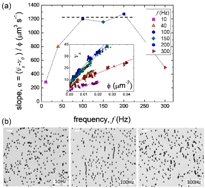
The data shown in Fig.2 were obtained at Hz, thus very close to . However, we also find that the mean velocity increases with the density for other frequencies but, as or , this effect becomes less pronounced. Fig.3(a) shows the slope obtained from the linear regression for different frequencies, inset Fig.3(a). For and (dashed line) we find that reaches a maximum constant value, where HIs completely dominate over dipolar forces. In this situation, we observe the formation of clusters that grow perpendicular to the -axis, as shown in the microscope image in the middle of Fig.3(b). In contrast, at low or high frequencies, the slow particle spinning (Fig.1(d)) reduces the effect of HIs favouring dipolar forces and thus the growth of clusters along the propulsion direction (), see left and right images in Fig.3(b). Now attractive dipolar forces slow down the mean velocities of the clusters, reducing the speed up effect. This is consistent with other cases of clustering induced by dipolar interactions in one 34 and two dimensions 36 were the mean velocity of the rollers was observed to saturate with the number of particles. Further, the competition between dipolar interactions and HIs do not dissolve the clusters, but rather induce a precessional-like motion of the particles and the formation of more irregular structures, as shown in VideoS3 of the supporting information.
5 Dynamic clustering
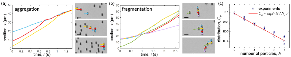
At large density the magnetic rollers tend to aggregate in form of small dynamic clusters which continuously break and reform during propulsion. Two typical situations are shown in Figs.4(a,b). The first one (Fig.4(a)) illustrates the formation of a three particle cluster that assembles along the ()-direction. Once formed, the clusters usually propel at a similar speed than the composing particles. The lifetime of the clusters is relative short as interaction with other incoming particles can easily break them. This is illustrated in Fig.4(b) where one particle is able of breaking a four particle cluster. During this fragmentation process, the hematite particles speed up, since they are literally pushed away by the flow field of the incoming roller. The microrollers form rather ”fragile” hydrodynamic states, in contrast to other clusters made of active or self-propelling particle systems. 37, 38, 39, 40, 41 In Fig.4(c) we analyse the cluster size distribution at a relative large density of particles, . Even if the maximum cluster size observed is limited to , we find that the data follow a simple exponential law, which gives a characteristic value . This behaviour is different than the one observed in other active systems, where the dynamic clustering process is usually describe by a mixed exponential and power law function. 41 In our case, the absence of an initial power law scaling in reflects the different cluster nature, where HIs make these structures rather fragile. Indeed, clusters made of chemically active particles 37, 42 or bacteria 43, 44, 45 can grow isotropically over a much larger area and the composing units present, apart from the random orientation during propulsion, other interactions competing with HIs. Instead our driven microrollers are characterized by almost deterministic trajectories with small thermal fluctuations, and the cluster aggregation/fragmentation process is driven by the sole HIs.
6 Conclusions
In this work we investigate the collective transport properties of anisotropic hematite rollers that are driven in a viscous fluid by an external rotating magnetic field. We find that at high driving frequency, HIs dominate and induce the formation of elongated clusters perpendicular to the direction of motion, even if dipolar interactions are repulsive for such configuration. Moreover the particle collective mean velocity linearly increases with the density, a fact that we explain on the basis of Blake’s tensor formalism applied to our colloidal rollers. 46
We note that Driscoll et al. 47 reported recently that a collection of microscopic magnetic rollers made of spherical particles with protruding hematite cubes, display a fingering instability produced by the hydrodynamic flow generated by their spinning. In such work the authors also report that the velocity of the rollers linearly grow with the particle density, and the density-dependent mean velocity has been later used to predict the formation of shock fronts in this system. 48 Our hematite colloidal rollers display relative stronger magnetic forces, a feature that may be used to further control dipolar interactions in contrast to hydrodynamic one. Indeed, it would be interesting to investigate in the future weather HIs can play an important role in the synchronization process of the magnetic rollers with the rotating field.
7 Appendix
7.1 Single particle dynamics
Isolated hematite particles are subjected to different forces during motion. Given the large density mismatch, , between hematite ( in bulk) and water (), the gravitational force acting on a spherical particle of radius can be estimated as , thus much higher than lift force , calculated Rashidi2016, Helgessen2018 for a similar spherical particle spinning at the maximum frequency of Hz. Thus, in absence of repulsive electrostatic interactions that float the particle at a distance of nm from the surface, the particles would touch the solid surface and display a stick-slip dynamics.
Another effect which may affect the roller dynamics at very low and high frequency, is the surface roughness. Its effect may be present in the asynchronous regime (see VideoS3 of the Supporting Information) when the particle perform a wobbling-like movement. We consider the particle roughness Smart1989 in terms of the typical size of surface asperities or bumps, . The solid friction becomes important when the size of the surface bumps is of the order of the thickness of the gap between the particle and plane Smart1993. In this situation, the hydrodynamic problem for a particle moving near the plane 24 is given by the following force and torque balance equations
| (9) |
and
| (10) |
where is the solid friction force and is the torque from the rotating magnetic field. Two different situations may be considered - motion without slip when and , where is a solid friction coefficient and the normal force. A simple estimate for the hematite particle under a rotating field with amplitude of the ratio shows that and the particle is in slipping regime when . Scaling with the sedimentation velocity and the angular velocity by give
| (11) |
and
| (12) |
From Eq.(11)
| (13) |
Inserting that in Eq.(12) we have
| (14) |
In dimensional units this gives
| (15) |
As a result for the ratio of the collective velocity of ensemble and velocity of the single particle we have
| (16) |
where is the surface fraction covered by the magnetic particles.
8 Acknowledgments
G. J. and P. T. acknowledge support from the European Research Council (ERC) under the European Union’s Horizon 2020 research and innovation programme (grant agreement No.: 811234). A.C. acknowledge support by grant of Scientific Council of Latvia lzp-2020/1-0149. P. T. acknowledges support from MICIU (grant No. PID2019-108842GB-C21), AGAUR (grant No. 2017-SGR-1061) and from the Generalitat de Catalunya via program ”Icrea Acadèmia”.
References
- Dobnikar et al. 2013 J. Dobnikar, A. Snezhko and A. Yethiraj, Soft Matter, 2013, 9, 3693–3704.
- Martin and Snezhko 2013 J. E. Martin and A. Snezhko, Rep. Prog. Phys., 2013, 76, 126601.
- Klapp 2016 S. H. L. Klapp, Curr. Opin. Colloid Interface Sci., 2016, 21, 76.
- Han et al. 2018 K. Han, C. W. S. IV and O. D. Velev, Adv. Funct. Mater., 2018, 28, 1705953.
- Marchetti et al. 2013 M. C. Marchetti, J. F. Joanny, S. Ramaswamy, T. B. Liverpool, J. Prost, M. Rao and R. A. Simha, Rev. Mod. Phys., 2013, 85, 1143.
- Bechinger et al. 2016 C. Bechinger, R. D. Leonardo, H. Löwen, C. Reichhardt, G. Volpe and G. Volpe, Rev. Mod. Phys., 2016, 88, 045006.
- Tierno et al. 2008 P. Tierno, R. Golestanian, I. Pagonabarraga and F. Sagués, Phys. Rev. Lett., 2008, 101, 218304.
- Morimoto et al. 2008 H. Morimoto, T. Ukai, Y. Nagaoka, N. Grobert and T. Maekawa, Phys. Rev. E, 2008, 78, 021403.
- Schmid et al. 2010 C. E. S. L. Schmid, M. F. Schneider, T. Franke and A. Alexander-Katz, Proc. Natl. Acad. Sci. U.S.A., 2010, 107, 535.
- Petit et al. 2012 T. Petit, L. Zhang, K. E. Peyer, B. E. Kratochvil and B. J. Nelson, Nano Lett., 2012, 12, 156.
- van Reenen et al. 2015 A. van Reenen, A. M. de Jong and M. W. J. Prins, Lab Chip, 2015, 15, 2864.
- Tasci et al. 2016 T. O. Tasci, P. S. Herson, K. B. Neeves and D. W. M. Marr, Nat. Comm., 2016, 7, 10225.
- Maier et al. 2016 F. J. Maier, T. Lachner, A. Vilfan, T. O. Tasci, K. B. Neeves, D. W. M. Marr and T. M. Fischer, Soft matter, 2016, 12, 9314–9320.
- Kaiser et al. 2017 A. Kaiser, A. Snezhko and I. S. Aranson, Sci. Adv., 2017, 3, e1601469.
- Han et al. 2018 K. Han, W. C. S. IV and O. D. Velev, Adv. Funct. Mater., 2018, 28, 1705953.
- Happel and Brenner 1973 J. Happel and H. Brenner, Low Reynolds Number Hydrodynamics, Noordhoff, Leiden, 1973.
- Purcell 1977 E. M. Purcell, Am. J. Phys., 1977, 45, 3–11.
- Berg and Anderson 1973 H. C. Berg and R. A. Anderson, Nature, 1973, 245, 380–382.
- DiLuzio et al. 2005 W. R. DiLuzio, L. Turner, M. Mayer, P. Garstecki, D. B. Weibel, H. C. Berg and G. M. Whitesides, Nature, 2005, 435, 1271–1274.
- Dreyfus et al. 2005 R. Dreyfus, J. Baudry, M. L. Roper, M. Fermigier, H. A. Stone and J. Bibette, Nature, 2005, 437, 862–865.
- Gao et al. 2010 W. Gao, S. Sattayasamitsathit, K. M. Manesh, D. Weihs and J. Wang, J. Am. Chem. Soc., 2010, 132, 14403.
- Howse et al. 2007 J. R. Howse, R. A. L. Jones, A. J. Ryan, T. Gough, R. Vafabakhsh and R. Golestanian, Phys. Rev. Lett., 2007, 99, 048102.
- Popescu 2020 M. N. Popescu, Langmuir, 2020, 36, 6861–6870.
- Goldman et al. 1967 A. J. Goldman, R. G. Cox and H. Brenner, Chem. Eng. Sci., 1967, 22, 637.
- Martinez-Pedrero et al. 2018 F. Martinez-Pedrero, E. Navarro-Argemí, A. Ortiz-Ambriz, I. Pagonabarraga and P. Tierno, Science Advances, 2018, 4, eaap9379.
- Massana-Cid et al. 2019 H. Massana-Cid, E. Navarro-Argemí, D. Levis, I. Pagonabarraga and P. Tierno, J. Chem. Phys., 2019, 150, 164901.
- Shull et al. 1951 C. G. Shull, W. A. Strauser and E. O. Wollan, Phys. Rev., 1951, 83, 333–345.
- Mansilla et al. 2002 M. V. Mansilla, R. Zysler, D. Fiorani and L. Suber, Physica B, 2002, 320, 206–209.
- Martinez-Pedrero et al. 2016 F. Martinez-Pedrero, A. Cebers and P. Tierno, Soft Matter, 2016, 12, 3688–3695.
- Adler 1946 R. Adler, Proceedings of the IRE, 1946, 34, 351 – 357.
- Helgesen et al. 1990 G. Helgesen, P. Pieranski and A. T. Skjeltorp, Phys. Rev. Lett., 1990, 64, 1425–1428.
- Belovs and Cēbers 2014 M. Belovs and A. Cēbers, Phys. Rev. E, 2014, 89, 052310.
- Blickle et al. 2005 V. Blickle, D. Babic and C. Bechinger, Appl. Phys. Lett., 2005, 87, 101102.
- Martinez-Pedrero et al. 2015 F. Martinez-Pedrero, A. Ortiz-Ambriz, I. Pagonabarraga and P. Tierno, Phys. Rev. Lett., 2015, 115, 138301.
- Lauga 2020 E. Lauga, The Fluid Dynamics of Cell Motility, Cambridge University Press, 2020.
- Martinez-Pedrero and Tierno 2015 F. Martinez-Pedrero and P. Tierno, Phys. Rev. Applied, 2015, 3, 051003.
- Theurkauff et al. 2012 I. Theurkauff, C. Cottin-Bizonne, J. Palacci, C. Ybert and L. Bocquet, Phys. Rev. Lett., 2012, 108, 268303.
- Buttinoni et al. 2013 I. Buttinoni, J. Bialké, F. Kümmel, H. Löwen, C. Bechinger and T. Speck, Phys. Rev. Lett., 2013, 110, 238301.
- Bialké et al. 2015 J. Bialké, T. Speck and H. Löwen, J. Non-Cryst. Solids, 2015, 407, 367.
- Massana-Cid et al. 2018 H. Massana-Cid, J. Codina, I. Pagonabarrag and P. Tierno, Proc. Nat. Acad. Sci. U.S.A., 2018, 115, 10618–10623.
- Ginot et al. 2018 F. Ginot, I. Theurkauff, F. Detcheverry, C. Ybert and C. Cottin-Bizonne, Nat. Commun., 2018, 9, 696.
- Pohl and Stark 2015 O. Pohl and H. Stark, Eur. Phys. J. E, 2015, 38, 93.
- Chen et al. 2012 X. Chen, X. Dong, A. Be’er, H. L. Swinney and H. P. Zhang, Phys. Rev. Lett., 2012, 108, 148101.
- Petroff et al. 2015 A. P. Petroff, X.-L. Wu and A. Libchaber, Phys. Rev. Lett., 2015, 114, 158102.
- Kirkegaard et al. 2016 J. B. Kirkegaard, A. O. Marron and R. E. Goldstein, Phys. Rev. Lett., 2016, 116, 038102.
- Blake and Chwang 1974 J. R. Blake and A. T. Chwang, J. Eng. Math., 1974, 8, 23–29.
- Driscoll et al. 2017 M. Driscoll, B. Delmotte, M. Youssef, A. D. Stefano Sacanna and P. Chaikin, Nat. Phys., 2017, 13, 375.
- Delmotte et al. 2017 B. Delmotte, M. Driscoll, P. Chaikin and A. Donev, Phys. Rev. Fluids, 2017, 2, 092301.