Simultaneous Object Reconstruction and Grasp Prediction
using a Camera-centric Object Shell Representation
Abstract
Being able to grasp objects is a fundamental component of most robotic manipulation systems. In this paper, we present a new approach to simultaneously reconstruct a mesh and a dense grasp quality map of an object from a depth image. At the core of our approach is a novel camera-centric object representation called the “object shell” which is composed of an observed “entry image” and a predicted “exit image”. We present an image-to-image residual ConvNet architecture in which the object shell and a grasp-quality map are predicted as separate output channels. The main advantage of the shell representation and the corresponding neural network architecture, ShellGrasp-Net, is that the input-output pixel correspondences in the shell representation are explicitly represented in the architecture. We show that this coupling yields superior generalization capabilities for object reconstruction and accurate grasp quality estimation implicitly considering the object geometry. Our approach yields an efficient dense grasp quality map and an object geometry estimate in a single forward pass. Both of these outputs can be used in a wide range of robotic manipulation applications. With rigorous experimental validation, both in simulation and on a real setup, we show that our shell-based method can be used to generate precise grasps and the associated grasp quality with over % accuracy. Diverse grasps computed on shell reconstructions allow the robot to select and execute grasps in cluttered scenes with more than % success rate.
I Introduction
Grasping objects is a fundamental robot capability. Given a 3D model of an object, there are numerous approaches for computing the 6DOF end-effector pose for grasping the object [1, 2]. In many applications however, a complete 3D model of the object is not available. Therefore grasps must be computed from sensor input which is typically in the form of an image or a partial point cloud of the object.
Recent works on grasp prediction explore two main approaches. Various object reconstruction methods are trained to generate object reconstructions [3, 4, 5, 6] as an intermediate step for grasp planning or the grasps or grasp quality are predicted directly using learning-based methods [7, 8, 9]. Object reconstruction methods have shown impressive results when trained on large datasets such as ShapeNet [10] or for specific object categories [11, 12, 13, 14, 15, 16, 17]. However, when trained on small but diverse grasping datasets such as YCB, the models fail to achieve good reconstruction quality and their generalizability is compromised [18, 19, 5]. End-to-end methods which generate grasp proposals directly from the sensor have been especially successful for top-down grasping with an overhead camera setup[7, 20]. Extending these approaches to 6-DOF grasp planning in a more general setting remains an active research topic [8, 21, 9]. Nonetheless, the success of these methods shows that accurate extraction of certain features from the object image/pointcloud such as width or thickness of the object is more important than reconstruction of every detail of the object geometry.
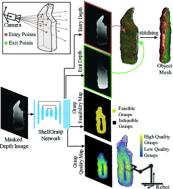
Motivated by these observations, we present Object Shell - a camera-centric object representation that forms the basis for our method to predict 3D object mesh as well as high quality grasp regions on the object from a single depth image (Figure 1). The depth image of an object captures information of where the camera rays enter the object. The shell representation augments this information with the depth of the points where the rays would exit the object. The set of all entry and exit points form the object shell. Since there is a one-to-one correspondence between the entry and exit points, we use a well-established UNet-style image-to-image architecture to infer the object shell in the camera frame from an input depth image. Even though the object shell is an approximation to the true object shape, the object thickness and overall geometry encoded in the object shell provides sufficient geometric information for 6-DOF grasp prediction. We exploit this shared geometric basis to train our netowrk –ShellGrasp-Net– for simultaneous object shell reconstruction and grasp quality prediction from a depth image.
Our experiments show that ShellGrasp-Net, trained only on depth images of simple synthetic shapes, outperforms the state-of-the-art object reconstruction methods when tested on realsense depth images of novel household objects from YCB dataset [22]. Furthermore, since the shell depth images already include neighborhood information of the points on the object, they provide partial meshes of the object which can be stitched together in linear time to provide a complete object mesh in the camera frame in a fraction of a second. With dense grasp sampling on reconstruction and geometric evaluation, we show that the grasps computed using shell reconstruction are more accurate than those using baseline reconstructions. With simulations in MuJoCo, we confirm that the quality of grasps estimated from object shell correlates with the stability of the grasps under external disturbance. Moreover, we show that we can bypass the need of sampling and optimization for best grasps by directly using the grasp quality map generated by ShellGrasp-Net. The argmax on this map provides the location on the object for maximum estimated grasp quality. Experiments on a real robot demonstrate that the grasps planned using our method provide % to % grasp success rate on singulated objects and over success rate in clutter.
In summary, the main contributions of this paper are:
-
•
A 3D object representation and its application for simultaneous camera-frame reconstruction and 6DOF grasp prediction
-
•
Data augmentation scheme that improves Sim2Real generalization for both ShellGrasp-Net and baseline methods
-
•
Simulation and robot experiments that analyze the effect of reconstruction accuracy on grasp success and demonstrate the effectiveness of predicted grasp quality maps for grasping with over % accuracy.
We start with an overview of the related work to highlight the novelty and significance of our contributions.
II Related Work
Single-view 3D Reconstruction: Generating a 3D reconstruction from a single view has been extensively studied on large synthetic datasets [10, 23] using various representations such as voxel grids, implicit functions, point-based, and mesh-based representations [13, 11, 12, 16, 17, 24, 25, 14, 15, 26]. The objects in these datasets are centered in the workspace and rotated only about vertical axis of canonical object frame. The methods trained on these datasets learn strong prior on object category and canonical object orientation frame. The orientation of the object geometry in the input is lost when the reconstruction is generated in the canonical object frame. For robotics applications, e.g. to pick up an object or to avoid collision with an object, we need reconstructions in the robot frame, or in the camera frame given the camera extrinsics. Pose registration required to align an object-frame reconstruction to the robot/camera frame is computationally expensive and can lead to errors.
A very few works in the literature look into camera-frame object reconstructions. Yao et al. [19] presented a method which estimates the object symmetry plane and predicts front and back orthographic views. Their method, trained separately for every new object class, requires a large number of images for training. Nicastro et al. [18] developed a method to estimate the thickness of an object in a masked depth image. They report that their method achieves good performance on a subset of YCB objects in the training data, but fails to generalize to novel object types. Merwe et al. [5] explore implicit surface representation method (PointSDF) and train on YCB dataset for camera frame reconstruction. In Section V-A, we show that shell reconstructions from our ShellGrasp-Net outperforms PointSDF and provides better generalization capability.
Shape Completion Based Grasping: Shape completion produces a full 3D representation of an object given a partial 3D pointcloud. Varley et al. [3] and Yan et al. [4] use voxel-grids to represent the object shape and use GraspIt! [1] and a custom ConvNet respectively to predict grasps on the reconstructed shapes. Voxel-grids have been shown to be inefficient in terms of memory footprint and reconstruction quality [16, 17, 14]. Merwe et al. [5] present an optimization-based method to use implicit object surface for grasp planning. However, they report that PointSDF reconstructions do not improve the grasp success rate.
Grasp Prediction: An active area of research in grasp planning is to generate grasp proposals directly from an input image. Mahler et al. [7] use millions of grasps in simulation and Pinto et al. [20] use self-supervision over 50K grasp trials to train neural networks to generate a grasp proposal from an image. These methods are limited to top-down 3-DOF grasping. Recent work by Mousavian et al. [21] and Sundermeyer et al. [9] present state-of-the-art methods to generate 6-DOF grasps on objects from a single view.
For 6-DOF grasping in general setting, the information needed to evaluate whether a robotic gripper could fit over an object is missing in the input from a single view as shown in Fig. 2. The SOTA grasping methods fail to implicitly reason about the true object shape and instead the grasps are overfit to the observed partial pointcloud in the input. In this paper we demonstrate that by jointly training for object reconstruction and grasp predictions, we can avoid such false positive grasps and accurately generate feasible grasps with high quality. Moreover, object reconstructions from our method can support grasp planning methods to further improve their performance as shown in Fig. 2,.
III Object Shell Representation and Relation to Grasping
In this section, we describe the shell representation and its advantages. We discuss how geometric information captured in shell reconstruction facilitates grasp computations.
III-A Object Shell Representation and its Characteristics
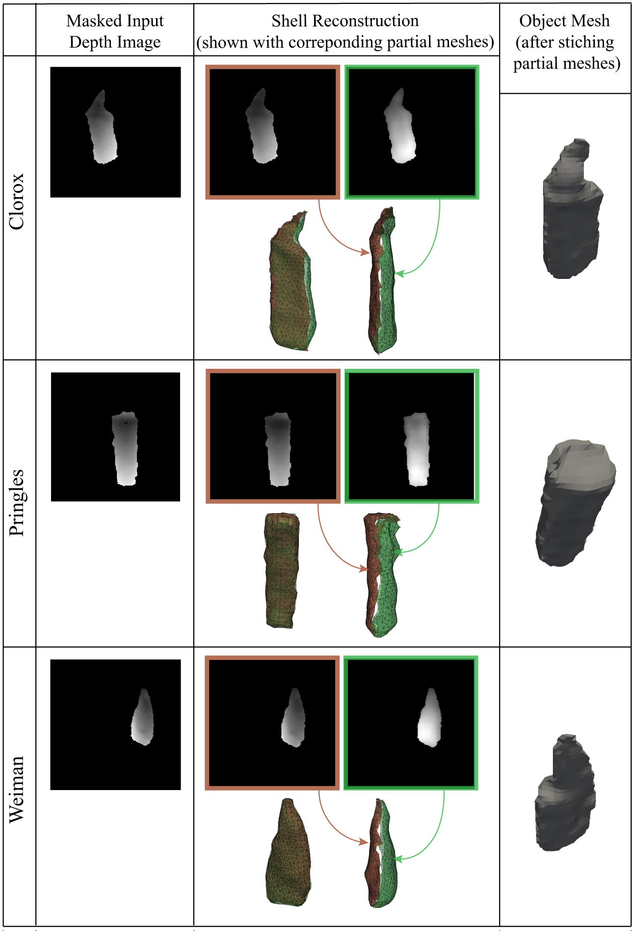
Consider the image of an object from an arbitrary view and the associated camera rays originating from the optical center. These rays intersect with the object as shown in Fig. 1. The Object Shell is formed by the entry and exit points on the object surface that the camera rays pass through, which can be represented as a pair of depth images.
The shell representation offers a few key characteristics. First, the shell is a view dependent description of the object. This property enables the generating the reconstruction directly in the camera frame. Second, and most importantly, the image-based shape representation allows posing the 3D reconstruction problem as 2D pixel prediction problem, which in turn allows using efficient 2D convolutions and well-proven image-to-image network architectures to establish input-output correspondence. As we show in this paper, this representation provides a nice reference frame to represent not just geometry but additional attributes such as grasp quality. Finally, the shell entry and exit images contain neighborhood information given by pixel adjacency. They directly provide partial meshes of the object which can be stitched together using the contours of the entry and exit images in linear time to generate an object mesh in the camera frame. The details of this stitching process are explained in Appendix A-A.
We note that the shell representation is not limited to convex objects. If we view the image plane as the X-Y plane and the optical axis as the Z axis, the shell representation poses no restrictions on the object’s projection onto the X-Y plane. It does impose a monotonicity constraint along the Z-axis that each ray enters and exits the object only once. We believe that this constraint is not overly restrictive: only 5 (wine glass, mug, bowl, pan, stacking block) out of 77 objects in YCB dataset violate this monotonicity constraint from some views. In Appendix A-I, we compare the shell and a SOTA method (PointSDF) reconstructions on adversarial objects and views and find that shell reconstruction still qualitatively performs better.
III-B Grasping with Shell Reconstruction
| Method(frame) | Shell(cam) | PtSDF(cam) | OCC(cam) | HOF(cam) | OCC(obj) | HOF(obj) | OCC(obj) | HOF(obj) |
|---|---|---|---|---|---|---|---|---|
| Alignment | Built-in | Built-in | Built-in | Built-in | ICP | ICP | CPD | CPD |
| Forward | 4.0E-3 | 9.0E-3 | 20.2E-3 | 6.1E-3 | 13.4E-3 | 5.2E-3 | 8.0E-3 | 4.2E-3 |
| Backward | 3.8E-3 | 6.9E-3 | 9.2E-3 | 5.7E-3 | 6.0E-3 | 4.5E-3 | 5.6E-3 | 4.1E-3 |
| Sum | 7.8E-3 | 15.9E-3 | 29.4E-3 | 11.8E-3 | 19.4E-3 | 9.7E-3 | 13.6E-3 | 8.3E-3 |
In this section, we establish the connection between object geometry and grasp quality in the context of object picking with a parallel-jaw gripper. A parallel-jaw grasp can be defined by a grasp pose (the position and orientation of the gripper), and grasp width (the distance between the fingers). These quantities can be computed from the object geometry explicitly as we explain in this section, or can be estimated simultaneously with the geometry as we show in Section IV.
Grasp Feasibility: We sample grasps on the visible pointcloud of the object and use the object reconstruction to evaluate grasp feasibility. We assign a grasp pose such that the axis joining the fingers (finger axis) is along the point normal and one of the fingers is over the visible pointcloud with the full ( mm) gripper opening. A grasp is geometrically feasible if the local object geometry is within the gripper opening and does not collide with the gripper. For a fixed grasp position, we change the grasp orientation about the finger axis (to eight discrete angles covering 360∘) to evaluate the feasibility. This procedure generates a Grasp Feasibility Map where every point in visible pointcloud is assigned to be grasp feasible or grasp infeasible. For all the feasible grasps, we compute the required grasp width from the bounds of the reconstruction inside the gripper envelope along the finger axis. In Section V-B, we show that evaluating the accuracy of the grasp width prediction serves as a good metric to understand how object reconstruction accuracy affects grasp planning.
Grasp Quality: A commonly accepted grasp quality metric is a measure of the external wrench the grasp can resist [27]. From the mechanics of a parallel-jaw grasp [2] (details in Appendix A-E), the grasp quality is inversely proportional to the Euclidean distance of the grasp position from the center of geometry of the object which can be obtained from the object reconstruction. We generate a Grasp Quality Map where every feasible grasp is assigned a relative quality score between 0 and 1 based on its Euclidean distance from the center of the object reconstruction.
IV Simultaneous Shell and Grasp Prediction
A straightforward way to use object shell reconstruction for grasp planning would be to first predict the shell and then to sample and choose the best quality feasible grasp as discussed in the previous section. However, we can make direct use of the information encoded in the network to simultaneously predict the object shell as well as grasp feasibility and quality maps as a single estimation problem. For our specific object picking application, the knowledge of grasp feasibility and quality maps allow us to bypass the need for sampling and exploration for good grasps over the entire object and rather directly narrow down on the regions of the object that would lead to stable grasps. In this section, we present ShellGrasp-Net – a network which can output object shell as well as per pixel grasp feasibility and quality directly from the input depth image of the object as shown in Fig. 1.
Network Architecture - The input to ShellGrasp-Net is a (potentially noisy) depth image and an object mask of the object, and the output is the entry and exit depth images representing the object shell, a grasp feasibility map as a binary image indicating per pixel grasp feasibility, and a grasp quality map as an image giving per pixel 0-1 relative grasp quality Fig. 1. We formulate the shell-grasp prediction network based on UNet - a popular image-to-image network architecture with skip connections [28]. We use a 4-level UNet architecture. The skip connections in UNet architectures is a powerful tool for tasks with direct relationship of input and output pixels. They enable feature extraction with large receptive fields while preserving low level features which is essential for high quality shell reconstructions and generalization to novel objects. For training the network, we use mean square error (MSE) image similarity loss for object shell (depth values) and grasp quality, and binary cross entropy (BCE) for grasp feasibility. The weighted sum of these three losses make up the total loss.
Training Data and Novel Augmentations - We use synthetically generated simple object mesh models and render depth images for training. We propose a data augmentation scheme for better Sim2Real generalization performance on real world objects and noisy depth images.
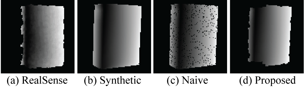
For the pre-render augmentation stage, noise is added to the XYZ positions of a subset of vertices of an object mesh followed by a smoothing operation to better resemble the uneven object surfaces observed in real-world depth images. The post-render augmentations consist of novel data dropout in addition to the additive and multiplicative Gaussian noise augmentations proposed in [7]. Depth images obtained by commodity sensors (Fig. 3 (a)) often contain missing values around object boundary as well as some regions inside the object. Dropping out random pixels from the image does not result in realistic images (Fig. 3 (c)). Our dropout scheme involves removing pixels with angles sharper than randomly sampled threshold and a small amount of pepper noise followed by multiple rounds of stochastic erosion of boundary pixels. The final result (Fig. 3 (d)) displays realistic dropout and object edge patterns.
For every rendered depth image, we generate ground truth object shell (entry and exit depth images) by computing camera ray intersection with ground truth object mesh. The ground truth binary grasp feasibility (0 or 1) and grasp quality [0-1] maps are generated following the method explained in Section III-B with ground truth mesh. We generate about 50K images with ground truth labels for training from about 5000 object meshes. The shape and view generation procedure and data augmentation are described in more detail with figures in Appendix A-B and Appendix A-C respectively.
V Experiments
In this section, first we experimentally evaluate shell reconstruction against several state-of-the-art methods in terms of geometric accuracy of the reconstruction. Then, we study the effect of reconstruction accuracy on grasp planning by dense sampling of grasps on reconstructions and evaluating their success rate geometrically and in Mujoco simulation. Finally, we evaluate the accuracy of ShellGrasp-Net predicted grasp feasibility and quality maps and demonstrate their use with grasping experiments on real robot.
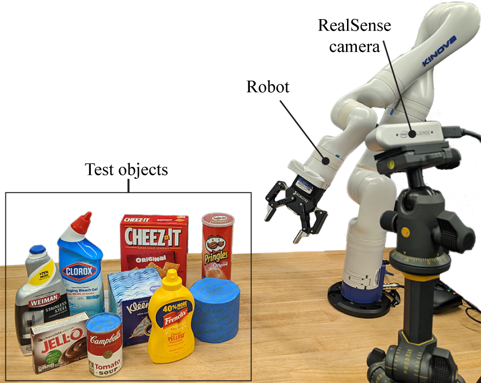
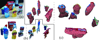
Test Data: We evaluate the shell and baseline methods on a set of real household objects (Fig. 4), mostly taken from the YCB dataset [22]. For experimental evaluations in the next three sub-sections, we collect 10 different views for each of our test objects using a RealSense camera. The object is moved to a different position and orientation for every new view. The object pose is recorded using AprilTags [29] to get the ground truth object mesh in the camera frame.
Baselines: We choose Occupancy Network (OCC) [17], Higher Order Function Network (HOF) [14] and PointSDF [5] as baselines. OCC-a representative implicit-function method and HOF-a representative direct method are shown to outperform state-of-the-art TSDF and Voxel based reconstruction methods respectively. For each of these two baselines, we train two versions where one produces the output directly in the camera frame and the other in the object frame, labeled as “(cam)” and “(obj)” respectively. Shell and these baselines are trained on the synthetic dataset explained in Section 5. PointSDF [5] is a camera frame reconstruction method for grasping. For our experiments, we use a PointSDF model pre-trained on YCB objects.
V-A Evaluation of Reconstruction Quality
Table I shows that shell reconstruction significantly outperforms baseline reconstruction methods in terms of Chamfer scores on the test dataset. Since our ground truth is in the camera frame, for methods that output reconstructions in the object frame, we align those reconstructions to the camera frame using Iterative Closest Point (ICP) [30] and more recent Coherent Point Drift (CPD) [31] methods with multiple initializations to get best fitting pose. We observe that object frame reconstructions with CPD alignment achieve the best Chamfer score for HOF and OCC baselines.
| Object | Shell | PtSDF | HOF | OCC | Visible | Visible Full |
|---|---|---|---|---|---|---|
| Cheezit | 87.4 | 42.4 | 96.8 | 71.2 | 0 | 27.0 |
| Jello | 95.2 | 76.6 | 72.2 | 61.0 | 1.0 | 77.0 |
| Pringles | 90.7 | 47.0 | 99.7 | 87.3 | 0 | 90.0 |
| Soup | 98.4 | 98.2 | 96.0 | 78.7 | 0 | 86.0 |
| Mustard | 94.0 | 30.8 | 71.5 | 18.6 | 0 | 72.4 |
| Clorox | 93.2 | 1.0 | 39.9 | 23.8 | 0 | 75.2 |
| Weiman | 93.8 | 7.3 | 56.0 | 74.5 | 0 | 65.4 |
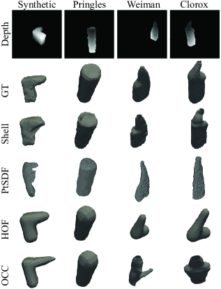
In Fig. 5, we observe that HOF and OCC methods overfit to training object shapes and provide limited generalization. PointSDF often generates thin reconstructions and loses some geometric details in the input. The shell reconstructions demonstrates better accuracy and generalization.
| Object | GFM | GFM | GQM | GQM (0.75) |
|---|---|---|---|---|
| F1 [0-1] | Accuracy [0-1] | RMSE [0-1] | RMSE [0-1] | |
| Cheezit | 0.88 | 0.9 | 0.19 | 0.12 |
| Jello | 0.95 | 0.92 | 0.3 | 0.15 |
| Pringles | 0.99 | 0.98 | 0.15 | 0.14 |
| Soup | 0.97 | 0.96 | 0.18 | 0.18 |
| Mustard | 0.89 | 0.82 | 0.22 | 0.15 |
| Clorox | 0.88 | 0.81 | 0.26 | 0.12 |
| Weiman | 0.85 | 0.79 | 0.27 | 0.16 |
| Bottle | 0.89 | 0.97 | 0.14 | 0.15 |
| Object | Cheezit | Jello | Pringles | Soup | Mustard | Clorox | Weiman | Bottle |
|---|---|---|---|---|---|---|---|---|
| Successful Grasps/10 | 10/10 | 10/10 | 9/10 | 10/10 | 10/10 | 9/10 | 9/10 | 9/10 |
In Appendix A-D, we discuss ablation studies with different variations of shell and HOF methods. We observe that removing the proposed data augmentation and keeping only the baseline augmentation adversely affects the Sim2Real robustness. The UNet skip connections considerably improve the performance of shell reconstruction.
V-B Evaluation of Reconstructions for Grasp Planning
In this section, we study the effect of object reconstruction accuracy on grasp planning. We compute a dense set of feasible grasps on the object reconstructions on the test dataset and evaluate their validity by checking the feasibility of those grasps on the ground truth object geometry. We define geometric grasp precision success rate as the percentage of the estimated feasible grasps that are feasible on the ground truth object geometries.
As shown in Table II, the grasp precision success rate on shell reconstruction is high across all the objects, while the performance for HOF and OCC reconstructions suffers for objects that are not similar to the training objects. The PointSDF reconstructions are often thinner than the actual object resulting into smaller estimated grasp width and large number of grasp failures. These results show the direct relation between the reconstruction performance of these methods and their effectiveness for grasp planning. The last column in Table II shows the results when using only the visible pointclouds for generating grasps and full gripper opening of mm. Kleenex box and Paper roll are bigger than full gripper opening and are correctly classified as infeasible to grasp by all the baselines except PointSDF.
To demonstrate the physical significance of the estimated grasp quality maps, we evaluate the stability of grasps under external disturbance in Mujoco [32]. We perform hundreds of grasp simulations across five grasp quality ranges for every test object. The Appendix A-G explains the simulation setup and the results in detail. The grasp quality estimated using the shell object reconstruction reflects in the grasp success rate. Over of the grasps in the high quality range succeed under external disturbance compared to only about grasps in the low quality range.
V-C Evaluation of Grasp Map Predictions
In this section, we first evaluate the accuracy of grasp feasibility and grasp quality maps computed by ShellGrasp-Net by comparing those with the ground truth maps computed on the test dataset. Next, we report the the success rate of grasps experiments on a real robot setup.
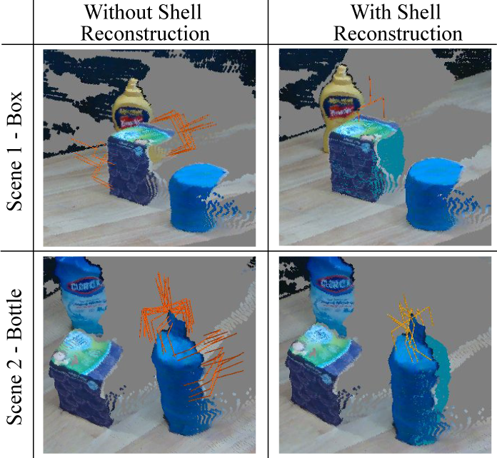
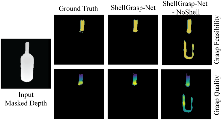
The binary grasp feasibility map indicates per pixel grasp feasibility (1 or 0). Table III shows that ShellGrasp-Net predicts the grasp feasibility map over % accuracy for more than half of the objects and more than % accuracy for rest of them. Kleenex and Roll are not graspable and are correctly identified so in grasp feasibility maps for those objects with % accuracy. We also include a bottle as an adversarial object to the test dataset. Only the neck of bottle is graspable while body of the body is too thick and not graspable. This allows us to test how accurate object reconstruction benefits grasp planning especially for avoiding false positive grasps as seen in Fig. 2. In an ablation study, we train ShellGrasp-Net with only grasp-map losses and no shell reconstruction loss (ShellGrasp-Net-NoShell). We observed that although the ablated network is able to predict grasp feasibility on most of the objects with similar accuracy as in Table III, its performance on bottle object is adversely affected. Similar to ContactGrasp-Net [9], ShellGrasp-Net-NoShell generates false positive grasp feasible regions on the body of the bottle as shown in Fig. 6. ShellGrasp-Net trained with the grasp-map as well as the shell losses avoids such false positive grasps consistently across different views and produces feasible grasps only on the neck of the bottle.
As shown in Table III, the root mean square (RMS) error on grasp quality estimation compared to the ground truth is about or less for all the objects. The RMS error in the predicted high quality grasp regions, where the grasp quality is more than , is less than for all the objects. This observation shows that exploiting the learnt representation of the object thickness as well as overall object geometry, ShellGrasp-Net is able to effectively identify regions on the objects that would lead to stable grasps. For example, in Fig. 6, the grasp quality map generated by the ShellGrasp-Net correctly shows that grasping the bottle object on the neck but closer to the body part would lead to more stable high quality grasp and the grasp quality reduces as the grasp position moves far from the body part.
With experiments on a real robot setup, we further examine the stability and success rate of the grasps planned using a grasp quality map estimated by ShellGrasp-Net. Given a masked depth image of a singulated object on a table, ShellGrasp-Net predicts grasp quality map on the input depth image. The robot selects a grasp on the object at the the location indicated by the maximum of the quality map, executes the grasp, and moves the object to the placement location. If the object is moved to the placement region without losing the grasp on the object, the grasp is counted as successful. Table IV shows the number of successful grasp trials when the test objects are placed in different poses. On average, we achieve % grasp success rate.
V-D Shell Reconstruction and Grasping in Clutter
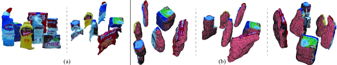
We demonstrate an application of object shell reconstruction and grasp prediction for a clutter removal task. Given an RGBD image of a scene, we segment it using Mask-RCNN [33]. Using the masked depth images of the objects, we get shell reconstructions and populate the scene with the reconstructed meshes (Fig. 7). A dense set of grasps from the predicted grasp maps allows us to select the grasps that are reachable for the robot without collision with the other objects.
Fig. 8 shows a scenario with low clutter. Since the front of all the objects is mostly visible from the camera, the object shells accurately generate complete object geometries. Note that the shell reconstruction method has not been trained for inpainting and therefore does not fill in the occluded parts of the front of the object. For example, in a dense clutter shown in Fig. 9-(a), the shell reconstructions for the Weiman bottle and Kleenex box, which are hidden behind the Mustard and Clorox bottles, are based on only small visible parts of these objects. As noted by Shin et al. in [34] for camera frame reconstruction methods, we observe that unless trained for a specific object category, our method can not generate a complete object reconstruction if large part of the object is not visible in the input image. Appendix A-I shows qualitatively better performance of Shell method compared to PointSDF for adversarial objects and views.
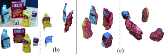
Practically, as objects are picked up by the robot, the objects in the background become more visible and accurate shell reconstructions and grasp maps of these objects can be produced. Fig. 7 shows compilation of object reconstructions as the robot cleared the scene in Fig. 9. As we can see in Fig. 7-(a) most of the object surfaces become visible as the clutter is slowly cleared. This allows the robot to generate accurate shell reconstructions shown in Fig. 7-(b).
For clutter removal experiments, we generated dense clutter scenes with six to seven objects in each. The robot was able to successfully remove all objects (except the non-graspable big objects) from the clutter and place them in a bin in all but one scene. In the failed scene, the Jello box was toppled during a grasp attempt and was no longer graspable. The robot was able to grasp all the objects in first attempts, except times where a second attempt was necessary. The average grasp success was (64 out of 68) when considering all the grasp attempts and (61 out of 65) when considering only the first grasp attempts. For similar scenes, we observed that ContactGrasp-Net [9] was successfully able to grasp most of the objects, however generated false positive grasps on the non-graspable or difficult to grasp objects as shown in Fig. 2. The average success rate with ContactGrasp-Net was (62 out of 70) where it failed to grasp bottle object twice and dropped Weiman bottle once after grasping, and in total five attempts were made for false positive grasps. The supplementary video shows the experiments and visulaizations of reconstructions in clutter.
VI Conclusion
In this paper, we present ShellGrasp-Net, a neural network trained to simultaneously generate an object’s 3D geometry and grasp quality map from an input depth image. To represent the object geometry directly in the camera frame, we introduced the notion of the “object shell”. The object shell can be represented as two images which, together, contain information about local neighborhoods and object thickness. The key merits of our method are: 1) it eliminates the need for explicit pose estimation since the reconstruction is performed directly in the camera frame, 2) despite being trained on a relatively small synthetic dataset, it generalizes well to novel objects and is robust to noise encountered in real depth images, and 3) grasp feasibility and quality estimation can be performed simultaneously with shell prediction. We showed both in simulations and real experiments that these advantages directly benefit the grasp planning process and lead to high grasp success rate across novel test objects and cluttered scenes.
The current version of ShellGrasp-Net requires the segmented depth image as input. It is also not trained to complete the input image in the presence of occlusions. In our future work, we plan to address these limitations by training the network to perform inpainting to handle large occlusions. We would also like to combine segmentation with geometry and grasp quality prediction so as to process the entire scene in a single pass for scene understanding and manipulation planning.
References
- [1] A. T. Miller and P. K. Allen, “Graspit! a versatile simulator for robotic grasping,” IEEE Robotics Automation Magazine, vol. 11, no. 4, pp. 110–122, 2004.
- [2] M. A. Roa and R. Suarez, “Grasp quality measures: Review and performance,” Autonomous Robots, vol. 38, pp. 65–88, 07 2014.
- [3] J. Varley, C. DeChant, A. Richardson, A. Nair, J. Ruales, and P. Allen, “Shape completion enabled robotic grasping,” in IEEE/RSJ International Conference on Intelligent Robots and Systems (IROS), 2017.
- [4] X. Yan, J. Hsu, M. Khansari, Y. Bai, A. Pathak, A. Gupta, J. Davidson, and H. Lee, “Learning 6-dof grasping interaction via deep geometry-aware 3d representations,” ICRA, pp. 1–9, 05 2018.
- [5] M. Merwe, Q. Lu, B. Sundaralingam, M. Matak, and T. Hermans, “Learning continuous 3d reconstructions for geometrically aware grasping,” IEEE ICRA, pp. 1516–11 522, 2020.
- [6] D. Yang, T. Tosun, B. Eisner, V. Isler, and D. Lee, “Robotic grasping through combined image-based grasp proposal and 3d reconstruction,” in 2021 IEEE International Conference on Robotics and Automation (ICRA). IEEE, 2021, pp. 6350–6356.
- [7] J. Mahler, J. Liang, S. Niyaz, M. Laskey, R. Doan, X. Liu, J. Aparicio, and K. Goldberg, “Dex-net 2.0: Deep learning to plan robust grasps with synthetic point clouds and analytic grasp metrics,” in Robotics: Science and Systems(RSS), 07 2017.
- [8] A. ten Pas, M. Gualtieri, K. Saenko, and R. Platt, “Grasp pose detection in point clouds,” The International Journal of Robotics Research, vol. 36, no. 13-14, pp. 1455–1473, 2017.
- [9] M. Sundermeyer, A. Mousavian, R. Triebel, and D. Fox, “Contact-graspnet: Efficient 6-dof grasp generation in cluttered scenes,” in IEEE ICRA, 2021.
- [10] A. X. Chang, T. Funkhouser, L. Guibas, P. Hanrahan, Q. Huang, Z. Li, S. Savarese, M. Savva, S. Song, H. Su, J. Xiao, L. Yi, and F. Yu, “ShapeNet: An Information-Rich 3D Model Repository,” Stanford University — Princeton University — Toyota Technological Institute at Chicago, Tech. Rep., 2015.
- [11] J. Wu, C. Zhang, T. Xue, B. Freeman, and J. Tenenbaum, “Learning a probabilistic latent space of object shapes via 3d generative-adversarial modeling,” in NeurIPS, vol. 29, 2016, pp. 82–90.
- [12] Y. Liao, S. Donné, and A. Geiger, “Deep marching cubes: Learning explicit surface representations,” in Conference on Computer Vision and Pattern Recognition (CVPR), 2018.
- [13] D. J. Rezende, S. M. A. Eslami, S. Mohamed, P. Battaglia, M. Jaderberg, and N. Heess, “Unsupervised learning of 3d structure from images,” in NeurIPS, 2016, p. 5003–5011.
- [14] E. Mitchell, S. Engin, V. Isler, and D. D. Lee, “Higher-order function networks for learning composable 3d object representations,” in International Conference on Learning Representations (ICLR), 2020.
- [15] N. Wang, Y. Zhang, Z. Li, Y. Fu, W. Liu, and Y.-G. Jiang, “Pixel2mesh: Generating 3d mesh models from single rgb images,” in ECCV, 2018.
- [16] J. J. Park, P. Florence, J. Straub, R. Newcombe, and S. Lovegrove, “Deepsdf: Learning continuous signed distance functions for shape representation,” in CVPR, June 2019.
- [17] L. Mescheder, M. Oechsle, M. Niemeyer, S. Nowozin, and A. Geiger, “Occupancy networks: Learning 3d reconstruction in function space,” in CVPR, 2019.
- [18] A. Nicastro, R. Clark, and S. Leutenegger, “X-section: Cross-section prediction for enhanced rgbd fusion,” in ICCV, 2019.
- [19] Y. Yao, N. Schertler, E. Rosales, H. Rhodin, L. Sigal, and A. Sheffer, “Front2back: Single view 3d shape reconstruction via front to back prediction,” IEEE/CVF Conference on Computer Vision and Pattern Recognition (CVPR), pp. 528–537, 2020.
- [20] L. Pinto and A. Gupta, “Supersizing self-supervision: Learning to grasp from 50k tries and 700 robot hours,” in IEEE ICRA, 2016, pp. 3406–3413.
- [21] A. Mousavian, C. Eppner, and D. Fox, “6-dof graspnet: Variational grasp generation for object manipulation,” in International Conference on Computer Vision (ICCV), 2019.
- [22] B. Calli, A. Singh, A. Walsman, S. Srinivasa, P. Abbeel, and A. M. Dollar, “The ycb object and model set: Towards common benchmarks for manipulation research,” in 2015 International Conference on Advanced Robotics (ICAR), 2015, pp. 510–517.
- [23] Z. Wu, S. Song, A. Khosla, F. Yu, L. Zhang, X. Tang, and J. Xiao, “3d shapenets: A deep representation for volumetric shapes,” in CVPR, June 2015.
- [24] P. Achlioptas, O. Diamanti, I. Mitliagkas, and L. J. Guibas, “Learning representations and generative models for 3d point clouds,” International Conference on Machine Learning (ICML), 2018.
- [25] H. Fan, H. Su, and L. Guibas, “A point set generation network for 3d object reconstruction from a single image,” in CVPR, 2017, pp. 2463–2471.
- [26] G. Gkioxari, J. Malik, and J. Johnson, “Mesh r-cnn,” in IEEE/CVF International Conference on Computer Vision (ICCV), October 2019.
- [27] C. Ferrari and J. Canny, “Planning optimal grasps,” in Proceedings 1992 IEEE International Conference on Robotics and Automation, 1992, pp. 2290–2295 vol.3.
- [28] O. Ronneberger, P. Fischer, and T. Brox, “U-net: Convolutional networks for biomedical image segmentation,” in Medical Image Computing and Computer-Assisted Intervention (MICCAI). Cham: Springer International Publishing, 2015, pp. 234–241.
- [29] E. Olson, “AprilTag: A robust and flexible visual fiducial system,” in IEEE ICRA, 2011.
- [30] K. Arun, T. Huang, and S. Blostein, “Least-squares fitting of two 3-d point sets. ieee t pattern anal,” IEEE Transactions on Pattern Analysis and Machine Intelligence, pp. 698 – 700, 10 1987.
- [31] A. Myronenko and X. Song, “Point set registration: Coherent point drift,” IEEE Transactions on Pattern Analysis and Machine Intelligence, vol. 32, no. 12, pp. 2262–2275, 2010.
- [32] E. Todorov, T. Erez, and Y. Tassa, “Mujoco: A physics engine for model-based control,” in IEEE/RSJ International Conference on Intelligent Robots and Systems, 2012, pp. 5026–5033.
- [33] K. He, G. Gkioxari, P. Dollár, and R. Girshick, “Mask r-cnn,” 2017.
- [34] D. Shin, C. C. Fowlkes, and D. Hoiem, “Pixels, voxels, and views: A study of shape representations for single view 3d object shape prediction,” in IEEE Conference on Computer Vision and Pattern Recognition (CVPR), June 2018.
- [35] D. Lee and B. Schachter, “Two algorithms for constructing a delaunay triangulation,” International Journal of Computer and Information Sciences, 1980.
- [36] C. B. Choy, D. Xu, J. Gwak, K. Chen, and S. Savarese, “3d-r2n2: A unified approach for single and multi-view 3d object reconstruction,” in ECCV, 2016.
Appendix A Appendix
A-A Object Mesh Generation from Shell Representation
The pixels in the entry and exit depth images of the object shell can be back projected in 3D space to produce a point cloud representing the object geometry. The object geometry captured by the object shell is a subset of the complete object geometry. Particularly, it does not include the part of the object geometry that the camera rays do not intersect with. Directly using this object point cloud can be sufficient for some applications; however, for some applications it is desirable to have an object mesh.
Shell representation provides an efficient approach to stitch together the surfaces encoded by the two layers of shell representation to generate an object mesh. Operating on Shell representation is more efficient than operating on point clouds. For example, meshing or triangulating a point cloud involves an iterative process of locating the best triangle candidates, which takes time [35], where is the number of points. In contrast, the triangulation can be done in time using shell representation since the proximity relationship between the points is encoded in shell representation as the pixel neighborhoods and the one-to-one correspondence between entry and exit depth pixels. The linear time meshing algorithm is as follows. First, as shown in Fig. 1 and Fig. 11 , the Entry and Exit depth images of the shell are triangulated independently by adding a triangle between each set of 3 neighboring pixels. Next, the Entry and Exit sides are stitched together by adding triangles between Entry and Exit pixels along the object boundary within the two images. This shell-specific mesh generation algorithm is asymptotically faster than point cloud meshing methods, and it is one of the advantages of shell representation.
A-B Training Shape Generation
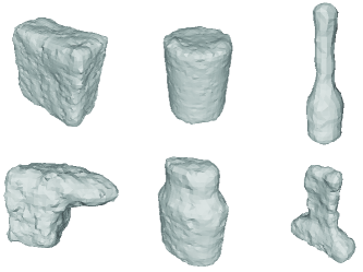
Training shapes are produced by applying a set of augmentation to one of the two base shapes: cube or cylinder. The first augmentation step is randomly resizing (“squishing”) the base shape along each axis. The resizing is constrained to keep the ratio between the smallest and largest sides of the shapes bounding box between : and :. After that, the object is uniformly re-scaled so that the biggest side of the bounding box would be between cm and cm. Next, of the object are augmented further by either shrinking a part of the object by up to or adding a Gaussian protrusion to the mesh of at most m. The set of shapes generated with the given procedure is diverse and balanced in terms of shape types and ratios. At the same time, the shape set is simple to generate and does not topologically cover all of the test set objects. This dataset allows us to study generalization properties of the reconstruction methods. Fig. 10 shows a few few examples of objects in our training dataset.
We render out 10 depth views for each shape, making the dataset of views in total. We place shapes into the world coordinate frame in random orientation. The shapes are placed such that the center of the shape bounding box is located within a sphere centered around a point m along the camera axis and with diameter of m. It is worth emphasising that here variation of object position is up to 10 times larger than than the object size, in contrast with the approach commonly taken in computer vision community [36] where variation of the object position is just a fraction of the object size. Large variation position makes it more difficult for deep learning models to directly predict the object position, but also makes the resulting models applicable to robotic applications with large workspaces.
A-C Data Augmentations
For the pre-render data augmentation, we first sample a random number of points from the mesh surface. The number of points is drawn from a uniform distribution between and . Then, we add noise to X, Y and Z locations of each of the sampled points. The noise magnitude for each axes of each point is drawn from IID uniform distribution ranging from mm to mm. The sampled points are then converted to a mesh using Poisson surface reconstruction process. We set the depth of the Poisson reconstruction to .
For the post-render data augmentations, we first randomly sample the maximum threshold angle from the range of to . The angle of each pixel is estimated by comparing pixel depth values to pixel neighbor depth values in the depth image. Next, we randomly drop out from to pixels as “pepper” noise. Next, we do several rounds of border erosion. First step of border erosion is identifying all of the border pixels. Note that the pepper noise added in the previous step will create additional internal borders. Next, a small percentage of the border pixels are removed from the image. This procedure is repeated for to rounds. We find that border erosion produces most realistic results when several first rounds are done at a coarser image resolution. Lastly, we choose from to of the pixels removed to be exempt from removal.
A-D Ablation Studies with Variations of Reconstruction Methods
In this section we consider variations of our shell reconstruction method and HOF method to gain better insights into their performance on our test dataset.
Table V lists the Chamfer scores on our test dataset for the variations of these methods. We observe that removing the proposed data augmentation and keeping only the baseline augmentation adversely affects the Sim2Real robustness. The UNet skip connections considerably improve the performance of shell reconstruction. The HOF(obj)+CPD baseline is able to outperform shell reconstruction on the synthetic validation set. This shows that although HOF achieves good performance in settings similar to training, it lacks the generalization to novel objects in a real-world environment. TABLE V: Reconstruction Methods Variations. The proposed depth augmentations and skip connections improve the quality shell reconstruction. Method Modification Chamfer Shell None 6.43E-3 Shell Baseline Augmentations 7.76E-3 Shell No Skip Connections 8.99E-3 Shell Synthetic Validation Set 5.99E-3 HOF None 8.34E-3 HOF Baseline Augmentations 8.75E-3 HOF Trained on ShapeNet 1.57E-2 HOF Synthetic Validation Set 5.42E-3
A-E Mechanics of Grasp Quality
A commonly accepted grasp quality metric is a measure of the maximum external wrench the grasp can resist [27]. The grasp feasibility evaluation provides a set of feasible grasps over the visible object surface. However, not all feasible grasps are equally robust under external disturbances.
The stability of a parallel-jaw grasp against an external wrench depends on the frictional resistance offered by the grasp (finger contacts) and the distance between the grasp location and the external wrench application point [2]. From the Coulomb friction law, the frictional resistance at finger contacts is proportional to the finger contact area. In the absence of any task-related external wrenches, only gravitational and inertial forces act at the center of mass of the object. Therefore, the grasp stability (quality) is directly proportional to the area of finger contacts and inversely proportional to the Euclidean distance of the grasp location from the center of mass of the object. We assume the objects are of uniform density, so the center of mass is the same as the center of geometry. Since the feasible grasps from the grasp feasibility map have at least the set threshold number of object points inside the grasp envelope, the finger contact area for these grasps is of the same order of magnitude and can be neglected when computing the grasp quality. Finally, the grasp quality is inversely proportional to the Euclidean distance of the grasp from the object’s center of geometry, which can be inferred from the object reconstruction.
Intuitively, an object grasped farther from the center of geometry is likely to rotate and fall out out the grasp under an external disturbance, therefore, such a grasp has low quality.
A-F Significance of Grasp Precision Success Rate
The geometric grasp precision success rate characterizes how closely the object reconstruction matches with the ground truth object model and its impact on the grasp planning process and grasp success. Moreover, it removes the dependence of grasp success on the relative sizes of the gripper and test objects used for the experiments which is overlooked in most the recent work on grasping [8, 21, 5]. A gripper with large opening can successfully grasp an object between fingers even with large errors in object model or grasp proposal. We believe this could partially explain why simple heuristic based grasping on only the visible pointcloud leads to high success rate in [5]. In our experiments as well, we confirm that grasping only based on the visible pointcloud with full gripper opening achieves good success rate as show in the last column of Table II. Therefore, particularly when evaluating reconstruction-based grasp planning methods, it is more informative to report the grasp precision success rate computed over the entire reconstruction than a top grasp success percentage with no constraint on the gripper opening used.
A-G Mujoco Setup and Experimental Procedure
We evaluate the physical significance of the quality of grasps estimated using shell reconstruction by testing the stability of those grasps under external disturbance .
| Object | Top [1.0-0.8) | T-Mid [0.8-0.6) | Mid [0.6-0.4) | Mid-L [0.4-0.2) | Low [0.2-0.0) |
|---|---|---|---|---|---|
| Cheezit | 82.7 | 72.9 | 70.0 | 43.8 | 15.6 |
| Jello | 90.4 | 88.1 | 78.1 | 68.0 | 33.5 |
| Pringles | 99.3 | 95.1 | 93.5 | 72.3 | 11.2 |
| Soup | 99.2 | 98.6 | 81.8 | 71.0 | 13.6 |
| Mustard | 95.4 | 90.9 | 80.4 | 38.7 | 5.1 |
| Clorox | 100.0 | 75.0 | 68.4 | 23.9 | 0.9 |
| Weiman | 92.1 | 84.5 | 32.1 | 14.3 | 1.1 |
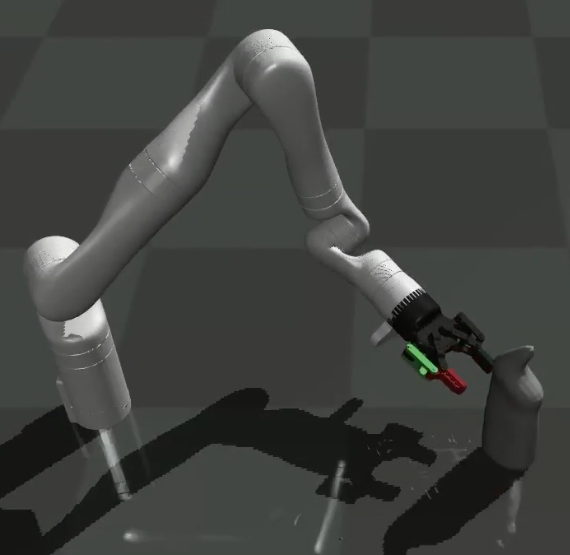
We built a setup in Mujoco simulator [32] with a Kinova Gen3 robot arm and a Robotiq 2F-85 gripper to replicate our real robot system. To minimize the effect of the arm motion planning limitations on diverse grasp evaluation, we place the test object in the robot’s dexterous workspace. Similar to the geometric grasp experiments, we evaluate the performance of precise grasping in Mujoco. For every test grasp sample, the robot approaches the object with a gripper opening only mm more than the estimated grasp width. The gripper is closed with a grip force of about N. The friction between the fingers and all the objects is set to . To evaluate the grasp stability, the grasped object is lifted up and an external force of N is applied in multiple directions at the center of geometry of the object. If the object is not moved in the grasp more than degrees, the grasp attempt is counted as success. Otherwise, the grasp attempt is counted as a failure.
Table VI shows the percentage of successful grasps across five grasp quality ranges from the grasp quality maps. For 10 test views per object, we perform 250 grasp simulations per object in every grasp quality range and report the average success rate in Table VI. The grasp quality estimated using the shell object reconstruction reflects well in the grasp success rate. More grasps in the high quality range resist the external disturbance force and succeed than the grasps in the low quality range. These results highlight that the shell object representation captures the key measures of the object geometry such as overall shape and the center well. These geometric features provide the scope for generating sets of grasps and their relative quality accurately.
A-H Detailed Comparison of our Shell Reconstruction Method with PointSDF
In this section we compare our Shell method and PointSDF baseline in detail with multiple examples.
Table VII compares the reconstructions from these two methods quantitatively as well as qualitatively. We observes that the shell reconstructions capture the object geometry details much more accurately. The geometric details from the input are lost in the PointSDF reconstructions. For example, the PointSDF reconstructions for Clorox and Weiman bottle appear to be some generic bottle shape prior the network has learnt. The Chamfer scores quantify the superior recosntruction accuracy of shell method.
A-I Adversarial object geometries and views for object reconstruction
Shell representation with a pair of depth images imposes a monotonicity constraint along the axis perpendicular to the image plane. We believe that this constraint is not overly restrictive: only 5 (wine glass, mug, bowl, pan, stacking block) out of 77 objects in YCB dataset violate this monotonicity constraint from some views. We sacrifice the performance on this small set of objects for the characteristics the shell representation provides for achieving generalization and superior performance on the larger class of objects. Reconstructing such complex objects is difficult for most of the reconstructions methods unless trained for those specific classes of objects.
For object and views where camera rays enter and exit the object more than once, the shell reconstruction may generate the outer geometry of the object or produce incomplete reconstruction as shown for a cup object in Table VIII. However, note that shell reconstructions look much better compared to PointSDF since they maintain the overall geometry of the object in the input intact.
As discussed in Section V-D, the object shell reconstruction can not generate complete object geometry if only small portion of the object surface is observed in the input data or if the input data is ambiguous. This limitation is present for any other reconstruction method as well, unless a strong shape prior is used or the method is overfitted to the training data and tested on the subset of the same data.
In Table VIII, we show object reconstructions for adversarial views where objects are seen from only narrower side. Both Shell reconstruction and PointSDF methods struggle for these views, since neither of them are trained to have strong shape prior. The shell reconstructions are qualitatively better than PointSDF reconstructions since they maintain the details in the input while completing the hidden back of the visible object using the average shape prior learnt. For the examples of Cheeze-it box and Ziploc box, the input contains information about only one face of the box-shaped object with no information from any other face to bound the backside of the object reconstruction. Both Shell and PointSDF generate a box of small thickness based on the prior learnt.
| GT | PointSDF | Shell | ||
| Roll | ![[Uncaptioned image]](/html/2109.06837/assets/figures/pointsdf/real_roll_view_001/gt_90.png) |
![[Uncaptioned image]](/html/2109.06837/assets/figures/pointsdf/real_roll_view_001/pointsdf_90.png) |
![[Uncaptioned image]](/html/2109.06837/assets/figures/pointsdf/real_roll_view_001/shell_90.png) |
|
![[Uncaptioned image]](/html/2109.06837/assets/figures/pointsdf/real_roll_view_001/gt_180.png) |
![[Uncaptioned image]](/html/2109.06837/assets/figures/pointsdf/real_roll_view_001/pointsdf_180.png) |
![[Uncaptioned image]](/html/2109.06837/assets/figures/pointsdf/real_roll_view_001/shell_180.png) |
||
![[Uncaptioned image]](/html/2109.06837/assets/figures/pointsdf/real_roll_view_001/gt_270.png) |
![[Uncaptioned image]](/html/2109.06837/assets/figures/pointsdf/real_roll_view_001/pointsdf_270.png) |
![[Uncaptioned image]](/html/2109.06837/assets/figures/pointsdf/real_roll_view_001/shell_270.png) |
||
| Chamfer | 2.06E-02 | 6.64E-03 | ||
| Weiman | ![[Uncaptioned image]](/html/2109.06837/assets/figures/pointsdf/real_weiman_cut_view_042/gt_90.png) |
![[Uncaptioned image]](/html/2109.06837/assets/figures/pointsdf/real_weiman_cut_view_042/pointsdf_90.png) |
![[Uncaptioned image]](/html/2109.06837/assets/figures/pointsdf/real_weiman_cut_view_042/shell_90.png) |
|
![[Uncaptioned image]](/html/2109.06837/assets/figures/pointsdf/real_weiman_cut_view_042/gt_180.png) |
![[Uncaptioned image]](/html/2109.06837/assets/figures/pointsdf/real_weiman_cut_view_042/pointsdf_180.png) |
![[Uncaptioned image]](/html/2109.06837/assets/figures/pointsdf/real_weiman_cut_view_042/shell_180.png) |
||
![[Uncaptioned image]](/html/2109.06837/assets/figures/pointsdf/real_weiman_cut_view_042/gt_270.png) |
![[Uncaptioned image]](/html/2109.06837/assets/figures/pointsdf/real_weiman_cut_view_042/pointsdf_270.png) |
![[Uncaptioned image]](/html/2109.06837/assets/figures/pointsdf/real_weiman_cut_view_042/shell_270.png) |
||
| Chamfer | 2.01E-02 | 7.53E-03 |
| GT | PointSDF | Shell | ||
| Clorox | ![[Uncaptioned image]](/html/2109.06837/assets/figures/pointsdf/real_clorox_view_048/gt_90.png) |
![[Uncaptioned image]](/html/2109.06837/assets/figures/pointsdf/real_clorox_view_048/pointsdf_90.png) |
![[Uncaptioned image]](/html/2109.06837/assets/figures/pointsdf/real_clorox_view_048/shell_90.png) |
|
![[Uncaptioned image]](/html/2109.06837/assets/figures/pointsdf/real_clorox_view_048/gt_180.png) |
![[Uncaptioned image]](/html/2109.06837/assets/figures/pointsdf/real_clorox_view_048/pointsdf_180.png) |
![[Uncaptioned image]](/html/2109.06837/assets/figures/pointsdf/real_clorox_view_048/shell_180.png) |
||
![[Uncaptioned image]](/html/2109.06837/assets/figures/pointsdf/real_clorox_view_048/gt_270.png) |
![[Uncaptioned image]](/html/2109.06837/assets/figures/pointsdf/real_clorox_view_048/pointsdf_270.png) |
![[Uncaptioned image]](/html/2109.06837/assets/figures/pointsdf/real_clorox_view_048/shell_270.png) |
||
| Chamfer | 1.97E-02 | 7.88E-03 | ||
| Kleenex | ![[Uncaptioned image]](/html/2109.06837/assets/figures/pointsdf/real_kleenex_view_009/gt_90.png) |
![[Uncaptioned image]](/html/2109.06837/assets/figures/pointsdf/real_kleenex_view_009/pointsdf_90.png) |
![[Uncaptioned image]](/html/2109.06837/assets/figures/pointsdf/real_kleenex_view_009/shell_90.png) |
|
![[Uncaptioned image]](/html/2109.06837/assets/figures/pointsdf/real_kleenex_view_009/gt_180.png) |
![[Uncaptioned image]](/html/2109.06837/assets/figures/pointsdf/real_kleenex_view_009/pointsdf_180.png) |
![[Uncaptioned image]](/html/2109.06837/assets/figures/pointsdf/real_kleenex_view_009/shell_180.png) |
||
![[Uncaptioned image]](/html/2109.06837/assets/figures/pointsdf/real_kleenex_view_009/gt_270.png) |
![[Uncaptioned image]](/html/2109.06837/assets/figures/pointsdf/real_kleenex_view_009/pointsdf_270.png) |
![[Uncaptioned image]](/html/2109.06837/assets/figures/pointsdf/real_kleenex_view_009/shell_270.png) |
||
| Chamfer | 2.35E-02 | 9.39E-03 |
| GT | PointSDF | Shell | ||
| Swiffer | ![[Uncaptioned image]](/html/2109.06837/assets/figures/pointsdf/real_swiffer_view_033/gt_90.png) |
![[Uncaptioned image]](/html/2109.06837/assets/figures/pointsdf/real_swiffer_view_033/pointsdf_90.png) |
![[Uncaptioned image]](/html/2109.06837/assets/figures/pointsdf/real_swiffer_view_033/shell_90.png) |
|
![[Uncaptioned image]](/html/2109.06837/assets/figures/pointsdf/real_swiffer_view_033/gt_180.png) |
![[Uncaptioned image]](/html/2109.06837/assets/figures/pointsdf/real_swiffer_view_033/pointsdf_180.png) |
![[Uncaptioned image]](/html/2109.06837/assets/figures/pointsdf/real_swiffer_view_033/shell_180.png) |
||
![[Uncaptioned image]](/html/2109.06837/assets/figures/pointsdf/real_swiffer_view_033/gt_270.png) |
![[Uncaptioned image]](/html/2109.06837/assets/figures/pointsdf/real_swiffer_view_033/pointsdf_270.png) |
![[Uncaptioned image]](/html/2109.06837/assets/figures/pointsdf/real_swiffer_view_033/shell_270.png) |
||
| Chamfer | 2.16E-02 | 7.75E-03 | ||
| Soup | ![[Uncaptioned image]](/html/2109.06837/assets/figures/pointsdf/real_soup_view_032/gt_90.png) |
![[Uncaptioned image]](/html/2109.06837/assets/figures/pointsdf/real_soup_view_032/pointsdf_90.png) |
![[Uncaptioned image]](/html/2109.06837/assets/figures/pointsdf/real_soup_view_032/shell_90.png) |
|
![[Uncaptioned image]](/html/2109.06837/assets/figures/pointsdf/real_soup_view_032/gt_180.png) |
![[Uncaptioned image]](/html/2109.06837/assets/figures/pointsdf/real_soup_view_032/pointsdf_180.png) |
![[Uncaptioned image]](/html/2109.06837/assets/figures/pointsdf/real_soup_view_032/shell_180.png) |
||
![[Uncaptioned image]](/html/2109.06837/assets/figures/pointsdf/real_soup_view_032/gt_270.png) |
![[Uncaptioned image]](/html/2109.06837/assets/figures/pointsdf/real_soup_view_032/pointsdf_270.png) |
![[Uncaptioned image]](/html/2109.06837/assets/figures/pointsdf/real_soup_view_032/shell_270.png) |
||
| Chamfer | 5.83E-03 | 6.65E-03 |
| GT | PointSDF | Shell | ||
| Bottle | ![[Uncaptioned image]](/html/2109.06837/assets/figures/pointsdf/real_bottle_view_008/gt_90.png) |
![[Uncaptioned image]](/html/2109.06837/assets/figures/pointsdf/real_bottle_view_008/pointsdf_90.png) |
![[Uncaptioned image]](/html/2109.06837/assets/figures/pointsdf/real_bottle_view_008/shell_90.png) |
|
![[Uncaptioned image]](/html/2109.06837/assets/figures/pointsdf/real_bottle_view_008/gt_180.png) |
![[Uncaptioned image]](/html/2109.06837/assets/figures/pointsdf/real_bottle_view_008/pointsdf_180.png) |
![[Uncaptioned image]](/html/2109.06837/assets/figures/pointsdf/real_bottle_view_008/shell_180.png) |
||
![[Uncaptioned image]](/html/2109.06837/assets/figures/pointsdf/real_bottle_view_008/gt_270.png) |
![[Uncaptioned image]](/html/2109.06837/assets/figures/pointsdf/real_bottle_view_008/pointsdf_270.png) |
![[Uncaptioned image]](/html/2109.06837/assets/figures/pointsdf/real_bottle_view_008/shell_270.png) |
||
| Chamfer | 3.10E-02 | 1.08E-02 |
| Visible PCL | PointSDF | Shell | ||
|---|---|---|---|---|
| Clorox | View 0 | ![[Uncaptioned image]](/html/2109.06837/assets/figures/adv/clorox_view11/snapshot04_L01.png) |
![[Uncaptioned image]](/html/2109.06837/assets/figures/adv/clorox_view11/snapshot04_L02.png) |
![[Uncaptioned image]](/html/2109.06837/assets/figures/adv/clorox_view11/snapshot04_L00.png) |
| View 1 | ![[Uncaptioned image]](/html/2109.06837/assets/figures/adv/clorox_view5_from_new/snapshot00_L01.png) |
![[Uncaptioned image]](/html/2109.06837/assets/figures/adv/clorox_view5_from_new/snapshot00_L02.png) |
![[Uncaptioned image]](/html/2109.06837/assets/figures/adv/clorox_view5_from_new/snapshot00_L00.png) |
|
| Cup | View 0 | ![[Uncaptioned image]](/html/2109.06837/assets/figures/adv/cup_view11/snapshot00_L01.png) |
![[Uncaptioned image]](/html/2109.06837/assets/figures/adv/cup_view11/snapshot00_L02.png) |
![[Uncaptioned image]](/html/2109.06837/assets/figures/adv/cup_view11/snapshot00_L00.png) |
| View 1 | ![[Uncaptioned image]](/html/2109.06837/assets/figures/adv/cup_view15/snapshot01_L01.png) |
![[Uncaptioned image]](/html/2109.06837/assets/figures/adv/cup_view15/snapshot01_L02.png) |
![[Uncaptioned image]](/html/2109.06837/assets/figures/adv/cup_view15/snapshot01_L00.png) |
| Visible PCL | PointSDF | Shell | ||
|---|---|---|---|---|
| Weiman | View 0 | ![[Uncaptioned image]](/html/2109.06837/assets/figures/adv/weiman_view1_from_new/snapshot00_L01.png) |
![[Uncaptioned image]](/html/2109.06837/assets/figures/adv/weiman_view1_from_new/snapshot00_L02.png) |
![[Uncaptioned image]](/html/2109.06837/assets/figures/adv/weiman_view1_from_new/snapshot00_L00.png) |
| View 1 | ![[Uncaptioned image]](/html/2109.06837/assets/figures/adv/weiman_view6/snapshot00_L01.png) |
![[Uncaptioned image]](/html/2109.06837/assets/figures/adv/weiman_view6/snapshot00_L02.png) |
![[Uncaptioned image]](/html/2109.06837/assets/figures/adv/weiman_view6/snapshot00_L00.png) |
|
|
Cheeze-it |
View 0 | ![[Uncaptioned image]](/html/2109.06837/assets/figures/adv/cheeze/snapshot00_L01.png) |
![[Uncaptioned image]](/html/2109.06837/assets/figures/adv/cheeze/snapshot00_L02.png) |
![[Uncaptioned image]](/html/2109.06837/assets/figures/adv/cheeze/snapshot00_L00.png) |
|
Ziploc |
View 0 | ![[Uncaptioned image]](/html/2109.06837/assets/figures/adv/zip/snapshot00_L01.png) |
![[Uncaptioned image]](/html/2109.06837/assets/figures/adv/zip/snapshot00_L02.png) |
![[Uncaptioned image]](/html/2109.06837/assets/figures/adv/zip/snapshot00_L00.png) |