Wireless Semantic Communications
for Video Conferencing
Abstract
Video conferencing has become a popular mode of meeting even if it consumes considerable communication resources. Conventional video compression causes resolution reduction under limited bandwidth. Semantic video conferencing maintains high resolution by transmitting some keypoints to represent motions because the background is almost static, and the speakers do not change often. However, the study on the impact of the transmission errors on keypoints is limited. In this paper, we initially establish a basal semantic video conferencing (SVC) network, which dramatically reduces transmission resources while only losing detailed expressions. The transmission errors in SVC only lead to a changed expression, whereas those in the conventional methods destroy pixels directly. However, the conventional error detector, such as the cyclic redundancy check, cannot reflect the degree of expression changes. To overcome this issue, we develop an incremental redundancy hybrid automatic repeat-request (IR-HARQ) framework for the varying channels (SVC-HARQ) incorporating a novel semantic error detector. The SVC-HARQ has flexibility in bit consumption and achieves good performance. In addition, SVC-CSI is designed for channel state information (CSI) feedback to allocate the keypoint transmission and enhance the performance dramatically. Simulation shows that the proposed wireless semantic communication system can significantly improve the transmission efficiency.
Index Terms:
IR-HARQ, CSI feedback, semantic communication, video conferencing, facial keypoints.I Introduction
In semantic communications[1], the shared and local knowledge, extracted from the set of transmission contents, helps compress transmission information and correct the transmission errors according to semantic correlation. However, the design of a practical semantic transceiver is difficult, especially the extraction of semantic knowledge using traditional methods due to lack of appropriate mathematical models. Deep learning (DL) makes the implementation of semantic communication possible as evidenced by many related works [2, 3, 4].
DL can potentially address many challenging issues [5, 6, 7, 8, 9] in communication systems, such as nonlinear interference, insufficient pilots, channel estimation, channel coding, channel state information (CSI) feedback, and autoencoder-based communication systems. These studies focus on the technical level and exploit DL to extract the features of channel environments and outperform the traditional design. In semantic communications, DL is used to extract the semantic information from contents, and shared and local knowledge in the semantic level is implicitly contained in the trained parameters. DL-based semantic communication systems are usually designed using joint source and channel coding methods and trained for a specific transmission content, including image [10, 11, 12, 13], video [14], speech [15], and text [16, 17, 18]. Furthermore, for some specific tasks, such as object recognition [13] and scene classification [19] tasks, semantic communications can significantly reduce the transmission overhead.
Video conferencing becomes an essential part of our work at present, especially during the pandemic of COVID-19. A high-resolution video transmission requires a huge amount of transmission resources. Therefore, it is very challenging, especially for conferencing over mobile phones. Driving a video with a few keypoints [20] is widely applied in face-swapping. The keypoints of the frames from a driving video are extracted to represent the motion of facial expressions, and a generator is exploited to enable a source image to move similarly to the driving video. In [21], the facial driving video is considered the transmitted video, and the receiver can restore the driving video from the transmitted keypoints and the photo of the speaker. However, the existing studies only relate to the source coding module, and the impact of the errors from the physical channel transmission is unclear. In addition, a semantic-based video conferencing transmission should protect key information facing physical transmission errors and the received videos should be acceptable under varying channels.
A basal network for the semantic-based video conferencing called SVC is established into a three-level framework. First, we investigate the entire transmission process and analyze the difference between the semantic and conventional errors. Then, we add acknowledgement (ACK) feedback to the SVC; it is a widely used technique in the conventional wireless communications to ensure a successful semantic transmission. An incremental redundancy hybrid automatic repeat request (IR-HARQ) framework for the SVC, called SVC-HARQ, is proposed to guarantee the quality of the received frames when facing wicked channels. Then, the transmitter learns to allocate information with different importance according to signal-to-noise ratios (SNR) at different subchannels with the help of CSI, which is called SVC-CSI. The major contributions of this work are summarized as follows:
1) Establishing SVC framework. The state-of-art technology to restore the image from several keypoints has achieved a huge compression ratio. Thus, we exploit the technology to cope with the channel distortion. Different from the huge compression ratio (only few number of keypoints) that causes the transmitted image to lose the detailed expressions, the simulation results show that transmission errors in physical channel transmission may change the locations of the keypoints and lead to inaccurate expressions. Nevertheless, these errors may be visually acceptable through semantic processing. On the contrary, the errors usually destroy the pixels directly for the conventional methods.
2) Combining with HARQ scheme. To guarantee the feasibility of the SVC under varying channels, the IR-HARQ feedback framework for the SVC, called SVC-HARQ, is developed. Compared with the conventional bit error detection using cyclic redundancy check, a semantic error detector is used to decide whether the received frame requires an incremental transmission. The semantic error detector exploits the fluency of the video to check of the received frame. The simulation results demonstrate that the inaccurate keypoints usually reduce the fluency. The proposed SVC-HARQ can adapt different bit error rates (BER) and require to transmit fewer bits than the competing methods.
3) Exploiting CSI. The CSI is exploited so that optimal transmitted information with different importance can be allocated automatically on different subchannels, which is called SVC-CSI. The SVC-CSI learns to allocate more information at the subchannels with high SNRs than those with low SNRs. An extra incremental transmission is trained without employing CSI because the performance of the SVC-CSI becomes worse when the testing channel environment is different from the training environment; thus, it shall be robust to varying channels and is called SVC-CSI-HARQ.
The rest of this paper is organized as follows. Section II introduces the system model and the related methods, including conventional IR-HARQ and adaptive modulation. Then, we describe the proposed networks in Section III. In Section IV, we demonstrate the superiority of the proposed networks in terms of semantic metrics and the required bits. Finally, Section V concludes this paper.
II System Model and Related Works
In this section, we first describe the existing frameworks on semantic networks and then introduce some important techniques in wireless communications that can potentially help semantic transmission. Finally, we discuss the challenges when applying the semantic transmission over the wireless communication systems.
II-A Semantic Frameworks
To transmit source information, such as a picture , the semantic transmitter first extracts its meaning. The semantic extractor plays a similar role to the source encoder in the conventional communication systems and is denoted as , where is the parameter set for semantic extraction. Then, the channel encoder, , can be designed separately or jointly with the semantic extractor and the encoded symbols are generated for channel transmission. The whole encoder process can be expressed as
| (1) |
where denotes the parameter set for semantic channel encoder. The transmitted picture can be recovered at the receiver by
| (2) |
where and represent the semantic source decoder and channel decoder, respectively. As indicated in [1], the semantic processing and transmission in the semantic communications are remarkably different from the conventional ones. Meanwhile, the local and shared knowledge in the semantic systems plays a major role. Semantic knowledge can be exploited implicitly or explicitly, as summarized in the following:
1) Implicit Semantic Knowledge. In these designs [14, 15, 16, 17], the local and shared knowledge is implicitly contained in the trainable parameters and the transceivers are usually trained in an end-to-end manner. The impact of physical channels is also learned implicitly. These methods automatically extract semantic features and cope with the distortion and interference in the physical channels. However, the trained parameters are difficult to adjust under changing transmit sources or physical environments.
2) Explicit Semantic Knowledge. In some specific tasks, the semantic knowledge is shared explicitly. For example, the semantic network in [22] shares the most important features in the image so that the received image can be classified better than the conventional methods. In [21], the photo of the speaker is shared because the appearance of the speaker has no much change during a speech. The explicit shared knowledge can be adjusted according to the change in the source information, such as replacing the photo for the next speaker.
Apart from the semantic knowledge, the existing methods have not considered adjusting the settings under different channel environments. Therefore, the semantic methods cannot adapt to the physical channel variation.
II-B Link settings in the conventional methods
In this section, we introduce two key techniques in wireless communications to cope with changing environments, which can be exploited in semantic system design. In modern communication systems with HARQ, the corrupted packets are retransmitted. IR-HARQ can balance the requirements of transmission resources and accuracy and is a popular option. To establish an IR-HARQ system, we need to have a channel encoder and an error detector. If the semantic symbols, , are protected by a conventional channel encoder, , then the coded symbol can be expressed as
| (3) |
In [23], the coded symbol vector can be divided into and with , where corresponds to coded semantic symbols with high coding rate, and represent the incremental symbols. The high code rate symbols, , are transmitted first. Denote as the received symbols corresponding to . The recovered semantic symbols can be expressed as,
| (4) |
The conventional CRC error detector is widely used for HARQ systems and extra parity bits are coded from and transmitted at the very beginning. With extra parity bits at the receiver, , ACK information can be generated by
| (5) |
where denotes the error detection process. The feedback signal when no error is found; otherwise, .
The incremental symbols, , need to be transmitted to decrease the code rate if some errors are founded (). The received coded symbols are combined together and decoded again, yielding
| (6) |
If the decoded result still has errors, then the retransmission starts, and the above process is repeated. This IR-HARQ method can deal with the varying channels in different time slots.
In addition, diversity on channel conditions at different frequencies of the same time slot can be exploited. If orthogonal frequency division multiplexing (OFDM) is used, then the overall channel bandwidth can be divided into parallel flat fading subchannels with different SNRs [24]. For OFDM systems, the subchannel gains are different, whereas the noise powers at different subchannels are the same. Then, the overall SNR can be expressed as
| (7) |
where and are the frequency response and transmit symbols at the -th subchannel, respectively. The is the noise power at the receiver. Once and are available at the transmitter, the modulation of the can be adaptive to cope with the changing gains of the subchannels.
Although the combination of the semantic networks and conventional link adaptive methods is naturally considered, the novel mechanism on semantic transmission brings challenges on the design in the technical level. As a deep and inexplicable network, the performance of the semantic-based transceiver must be guaranteed under varying physical environments.
III Transceiver design for Semantic video conferencing
In this section, we introduce novel architectures for semantic video conferencing, which exploit conventional strategies in wireless communications. We start with a basic network as a semantic source encoder. Then, a novel error detector is proposed to generate an ACK feedback. The basic network is expanded into the HARQ mode to cope with varying channels at different time slots. Finally, the CSI for each subchannel is fed back to the semantic transmitter for adaptive modulation.
III-A Basic Semantic Network for Video Conferencing
Restoring a specific face in an image from few keypoints has been studied in [21, 20]. In these methods, the keypoints contain the changing information of facial expression and manner. Other information, such as appearance features, does not change during a speech and can be shared to the receiver in advance. Besides, as presented in [21], the keypoints can be compressed and encoded to improve the transmission efficiency. The above methods dramatically reduce the requirement of transmit resource. However, the existing methods only focus on the framework of source coding and ignore the impact of varying wireless channels.

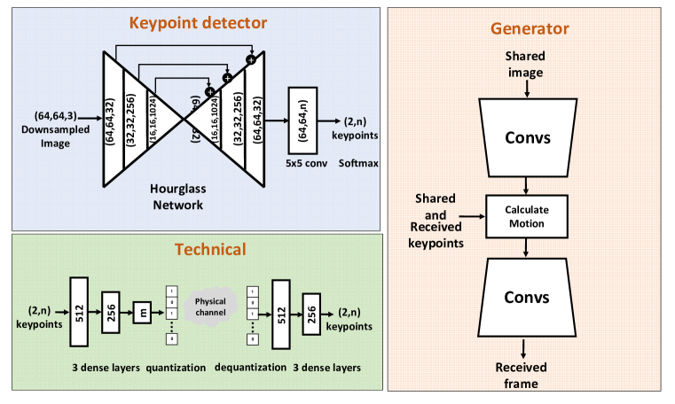
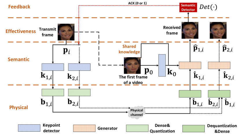
A complete semantic video conferencing framework is shown in Fig. 1, where the simple dense layers are introduced as a channel coding module. Fig. 1(a) shows a semantic video conferencing framework, called SVC. The whole framework consists of three levels similar to [1], including effectiveness, semantic, and technical levels. The effectiveness level delivers the motion and expression of the speaker. The conventional goal is to minimize the difference of the transmitted and recovered frames. At the semantic level, the photo of the speaker is shared in advance given that the speaker has no remarkable change during the speech. Usually, the first frame of the video is shared to the receiver for convenience, whereas a photo with distinct face is beneficial to generate a good image at the receiver. The keypoint detector extracts the movement of the face in the current frame, and these keypoints are transmitted at the technical level. Based on the received keypoints and the shared photo, the semantic part of the receiver reconstructs the frame. The networks in the technical level are trained to cope with the distortion and interference from the physical channels. From above description, the SVC has three subnets, including a keypoint detector and a generator in the semantic level, and an encoder-decoder in the technical level as shown in Fig. 1(b).
The keypoint detector extracts coordinates of the keypoints, , from the -th frame, , yielding
| (8) |
where denotes the set of trainable parameters of the keypoint detector. Specially, the first frame, , with its keypoints , is shared to the receiver. The keypoint detector consists of convolution neural networks (CNNs) similar to [25]. The inputted image matrix with sizes (256, 256, 3) is first downsampled to (64, 64, 3) by anti-alias interpolation to reduce complexity of the keypoint detector. Then, the image is processed by an hourglass network [26] with three blocks. Each block has a convolution operation with a Relu activation function, a batch normalization, and a average pooling. The network has 1024 maximum channels and 32 output channels. After the hourglass network, a convolution converts the output of CNN blocks from (64, 64, 32) into (64, 64, n), thereby dividing the image into grids. The softmax activation is applied to choose grid point with the largest output value. The selected grid points are normalized to .
The encoder-decoder consists of dense and quantization/dequantization layers. For the encoder, the keypoints of the -th frame, (expressed in coordinates), are considered as real numbers and processed by three dense layers, , with 512, 256, and neurons, where is the number of the transmit symbols. The first two layers use Relu activation function, and the last one uses Sigmoid activation function. Then, a two-bit quantization is applied to generate transmitted bits, . The whole process is expressed as
| (9) |
where is the set of trainable parameters in the dense layers.
The dequantizer, , at the receiver in the technical level is the inverse process of to recover the real numbers from the received bits, . The three dense layers, , have 512, 256, neurons, where the first two layers use Relu activation function and the last one uses Tanh to restore keypoints, . This process can be expressed as
| (10) |
where is the set of trainable parameters in the dense layers. The derivative of the quantization layer is replaced by that of the expectation in the backward pass because the gradient is truncated by the quantization[27].
The generator reconstructs the current frame from the shared image, , with its keypoints, , and the received keypoints of the -th frame, . This process is denoted as , where denotes the set of trainable parameters. Therefore, the -th frame can be recovered by
| (11) |
where the architecture of the generator is similar to that in [20] but without the Jacobian matrix.
The loss function consists of perceptual loss [28] based on a pretrained CNN, called VGG-19[29], a patch-level discriminator loss [30], and an equivariance loss [20], denoted as , , and , respectively. As a result, the overall loss function will be
| (12) |
Because the trainable parameters in the technical level are much fewer than other parts but still important, we add a mean-squared-error (MSE) loss function to train the technical level, yielding
| (13) |
The training processes are divided into three steps. At the beginning, the technical level is ignored, and the parameters in the keypoint detector and the generator are trained by , yielding
| (14) |
Then, the parameters in the technical level are trained by to restore the under the impact of the physical channel distortion,
| (15) |
Finally, all trainable parameters of the SVC are fine-tuned in the end-to-end manner as
| (16) |
The proposed SVC is a combination of the video synthesis and theoretic three-level semantic transmission in wireless communications. This basic framework is established and trained to study the impact of replacing video transmission with semantic keypoint transmission. The performance of the semantic transmission can be improved further by introducing the ACK feedback in wireless networks, as shown in from the following section.
III-B Semantic HARQ with ACK Feedback for Video Conferencing
HARQ can cope with time-varying channels in wireless communications. Retransmission and transmitting incremental symbols are flexible under changing channels with the ACK feedback. Thus, we develop a novel semantic video conferencing framework with HARQ, called SVC-HARQ, to improve semantic transmission.
As shown in Fig. 2, the receiver feeds an ACK signal back to the transmitter after the first transmission. The first transmission is the same as in Fig. 1 and the trained parameters can be used directly. The first transmitted bit vector, , can be expressed as
| (17) |
where is the set of trainable parameters in the keypoint detector, and is the set of trainable parameters in the encoder. Then, the recovered frame is
| (18) |
where is the set of parameters in the generator of the first transmission, and represents the received bit sequence at the first transmission. Then, the reconstructed frame, , is evaluated by a semantic detector. If the detector finds that is unacceptable, then =0 is fed back to the transmitter, and an incremental transmission is triggered.
The incremental bit sequence is transmitted to correct the errors. Different from the first transmission, the incremental transmission only concentrates on the fallible keypoints under wicked channel conditions. Thus, the incremental transmission also needs to be trained and has different trainable parameters, namely, , , and , for the keypoint detector, decoder, and generator, respectively. The incremental transmitted bit sequence is
| (19) |
and the recovered frame is
| (20) |
where is the received symbol vector that includes symbols corresponding to the first and incremental transmission.
The training process of the first transmission is the same as the SVC in Section III A. Then, all trained parameters are used as the initial values when training the parameters at the incremental transmission. Besides, the trained parameters, and , in the first transmission are fixed, and the process can be written as
| (21) | ||||
where
| (22) | |||
| (23) |
and indicates that the transmitted bits are with random errors due to channel distortion.
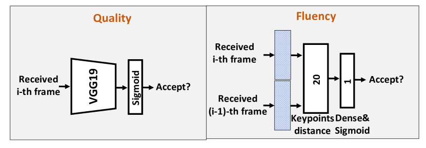
The above description indicates that the semantic detector is the key module of the SVC-HARQ because the detector directly decides whether the incremental transmission or retransmisstion is required. The conventional error detector, CRC, in the HARQ system is unsuitable for the SVC-HARQ because the difference between some subtle errors in the received frames are acceptable for the conferee. We use an image quality assessment method [31] to evaluate whether or not the received frame is acceptable. This quality assessment network can be obtained by transfer-learning a VGG-19 based classifier as shown in the left of Fig. 2(b). The VGG-19 based quality detector consists of VGG-19 and one dense layer with Sigmoid activation function to output frame quality indicator. The received frame is labeled as 1 for acceptable quality and 0 for unacceptable quality. The loss function is cross-entropy. With a trained detector, , the ACK feedback can be expressed as
| (24) |
In fact, the errors in the received keypoints dp not decrease the image quality directly, but they change the facial expressions. The generator can reconstruct an acceptable face image even if the keypoints have some errors because the general appearance is obtained from the shared image. The error keypoints only change the current expression and lead the video to be not fluent. To detect these changes, we propose a novel fluency detector on the right of Fig. 2(b). Thus, the detector needs to distinguish inappropriate expressions. We use a keypoint detector to capture the keypoints after . Then, we calculate the distance between the keypoints of and . A large distance means that the expression has a sudden change and the transmitted keypoints have some errors. The whole detection process can be expressed as
| (25) |
where is a dense layer with one neuron output and Sigmoid activation function. This detector is trained with cross-entropy as the loss function by the reconstructed frames collected by the SVC under different channels. The average keypoint distance (AKD) calculated by a pretrained facial landmark detector [32] is used for labeling, where the output of the detector is labeled with 1 if its AKD is smaller than five and 0 otherwise. The loss function is cross-entropy. After training, the fluency detector is also used similar to Eq. (24).
The proposed quality and fluency detectors are compared for HARQ systems under semantic-based video conferencing. Overall, an extra incremental transmission process can make the SVC more adaptive under changing channels if the semantic detector is effective. Moreover, the retransmission is started if the incremental symbols cannot correct the errors to reach the criterion of the detector.
III-C Adaptive Encoding with CSI Feedback
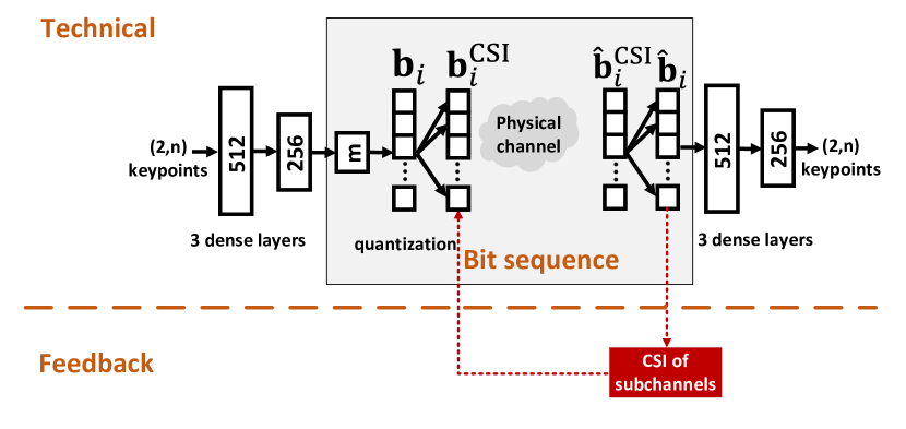

The above SVD methods exploit no CSI further. However, the noise power of the subchannels can be obtained by the receiver. For example, the frequency selective channels can be divided into different subchannels with different SNRs. We assume that the CSI of all subchannels is estimated by the receiver and shared to the transmitter. These channel conditions are exploited by the encoder-decoder at the technical level, which helps to protect the most important keypoints. The accurate CSI of each subchannel cannot be obtained in practice, and the feedback of the entire CSI values also requires resources. Thus, the receiver sorts the subchannels by their channel conditions and feeds this sequence back to the transmitter. This method simplifies the design of encoder-decoder in the technical level and reduces the feedback cost.
Compared with the original SVC, that with CSI feedback (SVC-CSI) only needs to add a sort module as shown in Fig. 3(a).The output of the sort module is denoted as , where its elements, representing subchannel gains, are in decreasing order. Then, is sent to the receiver. At the receiver, received is restored by . Because the other parts are the same as the SVC and the sort module of the SVC-CSI has no impact on the gradient, the SVC-CSI has the same training strategy as the SVC.
The above methods encode the keypoints into bit sequence, which can be easily applied into the conventional wireless communication systems, such as the OFDM system with quadrature amplitude modulation (QAM). Furthermore, joint design with modulation module to encode the keypoints into constellation points directly can further improve the performance. Thus, we also investigate the benefit of CSI feedback on the encoding keypoints into constellation points. In the left structure of Fig. 3(b), we directly replace the quantization in Fig. 3(a) with a dense layer and Tanh activation function. Its output has real symbols, which denote constellation points. These points are also rearranged according to CSI feedback. This constellation method is called full-resolution because the learned constellation points can appear anywhere in the constellation.
However, the full-resolution constellation is extremely complex for practical systems due to the finite precision. Thus, the constellation points need to be limited. We combine two bits into a real symbol similar to 16QAM. Meanwhile, each 2-bit vector is coded by the shared two trainable parameters, and , yielding
| (26) |
where the bits in are first modulated into the real symbols, , which only have four possible values, i. e., the constellation points only appear in 16 locations. The -symbol vector is also divided into subchannels and has been multiplied to different transmit powers, . Then, is rearranged to according to CSI feedback and sent to the receiver. The training process of these two methods with constellation points is still the same as that of SVC. Specially, this method is called quantized-resolution and only introduces parameters , , and .
In general, some bits/symbols always transmit under better channel conditions than the others with CSI feedback. Thus, the networks can learn to transmit important keypoints at the subchannels with high SNRs.
IV Numerical Results
In this section, we present the numerical results of different frameworks and discuss the pros and cons of the semantic-based video conferencing. We also compare their bit consumption (required number of bits) with competing ones.
IV-A Configurations of the simulation system
Training settings. The VoxCeleb dataset [33] has considerable face videos of speakers. These videos are pre-processed into the size of 256 256, and the videos without a distinct face are removed. Meanwhile, all the videos have only one speaker. After pre-processing, the training dataset has 2000 videos and the testing dataset has 100 videos, which have a total of about 500 different speakers. All networks are trained with Adam optimizer [34], and their initial learning rate is 0.0002.
Baseline. H264 is widely used as a commercial standard and usually occupies one-tenth bandwidth of the original video. The constant rate factor of the H264 code can be adjusted to generate different qualities and sizes of videos. Meanwhile, RS code is commonly applied in storage and channel coding in the wicked environment, such as deep space communications. In the following, RS means to encode information symbols into symbols. The redundancy symbols can correct error symbols. In this study, IR-HARQ strategy[35] encodes 64 information symbols into 255 symbols and transmit 127 symbols initially. The remaining 128 symbols are transmitted as the incremental redundancy, whereas the CRC detects errors after the first transmission.
Metrics. Three metrics are used to evaluate the results:
1) Average keypoint distance (AKD). We use a pretrained facial landmark detector [32] to evaluate the errors in our transmission. This pretrained detector extracts keypoints from the received and transmitted frame, and their average distance is computed. The AKD metric represents the motion and the changing expression of the face.
2) Structural similarity index measure (SSIM). SSIM evaluates the structural similarity among patches of the input images [36]. Therefore, SSIM, which is more robust than PSNR, is widely used as the metric of images.
3) Perceptual loss (Ploss). Perceptual loss is commonly used as a regularization method when training a network in the computer vision. Through calculating the sum of MSEs between the estimated and the true image at the different layers of a pretrained network, such as VGG, the similarity of the features represented by the perceptual loss. Here, we choose the perceptual loss metric proposed in [37].
IV-B Performance of semantic coding
In TABLE I, the SVC only transmits 160 bits per frame and the conventional H264 coding always has better SSIM performance than the SVC. However, the H264 requires more bits per pixel. Then, the two methods are compared in the metrics of Ploss and AKD, where the facial features are more important than the structural similarity. The SVC has a tremendous superiority in the bit consumption. The required bits per pixel of the H264 are about six times those of the SVC when their Ploss performances are similar and more than four times those of the SVC when their AKD performances are similar. In general, these metrics only represent different perspectives in the evaluation of semantic transmissions and the transmitted results should also be acceptable to humans. In the following section, we analyze the semantic errors through examples. The H264 with 0.0157 Bpp (bold in the table) is selected as the baseline and called H264 for convenience. Thus, the Ploss performance of the H264 and the SVC is the same without the impact of the channels. The AKD and SSIM metrics of the H264 are better than those of the SVC.
| H264 | Bpp | 0.0127 | 0.0136 | 0.0157 | 0.0185 | 0.0221 | 0.0261 | 0.0316 |
|---|---|---|---|---|---|---|---|---|
| SSIM | 0.759 | 0.780 | 0.803 | 0.826 | 0.847 | 0.865 | 0.882 | |
| Ploss | 0.227 | 0.201 | 0.187 | 0.159 | 0.136 | 0.116 | 0.094 | |
| AKD | 3.23 | 2.85 | 2.50 | 2.27 | 2.08 | 2.01 | 1.89 |
| SVC | Bpp | 0.0024 |
|---|---|---|
| SSIM | 0.671 | |
| Ploss | 0.186 | |
| AKD | 3.12 |


Although the H264 has the same Ploss performance as the SVC, the content loss is different, as shown in the examples in Fig. 4. The H264 loses the pixel information in all the areas of this frame; thus, the frame shows lower resolution than the original one. The lost information of the SVC usually cannot be distinguished as an independent image. Only the detailed expressions in the frame coded by SVC, such as the mouth in the circles, are different from the original because the semantic information is ignored when coding. This phenomenon is demonstrated in three metrics in Table I. Considered as a lower resolution image of the original frame, the structural information of the H264 frame is still reserved and the locations of the detected keypoints unchanged. Thus, the H264 has better SSIM and AKD metrics than the SVC. However, the quality of the SVC frame seems higher than the H264 to the human if the detailed expressions lead no ambiguities. Considering that the SVC only requires 1/6 of the bits of the H264, the semantic transmission is a better option for video conferencing, especially some conferees are using mobile phones in the crowd.
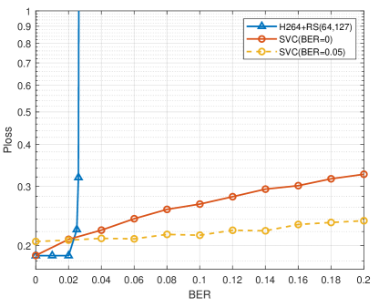
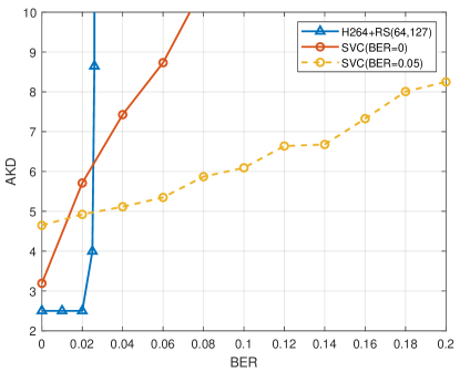
As shown in Fig. 5, the two methods have different sensitivities to the change of BER. The conventional H264+RS can perfectly restore the transmitted information when the errors are fewer than its correction capability. Thus, the performance of the H264+RS is unchanged when BER and decreases sharply when BER . The SVC methods always have better performance in terms of the three metrics when BER because the semantic transmission can still repair the semantic errors under high BER. However, the training environment is important for the performance of the SVC. The SVC (BER) is more suitable for low BER, and its performance becomes worse than the SVC (BER) when BER . That means the two SVC methods allocate different transmit resources for coping with errors implicitly.
In general, the SVC can save transmit resources for a high resolution video conferencing because it only transmits keypoints and has no need to compress pixel information such as H264. Moreover, the SVC has a superiority under the extremely high BER. However, the training BER affects the performance of the SVC, similar to selecting the code rate of channel coding. Thus, the IR-HARQ frame of the SVC is proposed and tested in the following section.
IV-C Performance of SVC-HARQ


Before discussing the performance of the SVC-HARQ, we first take a look at the difference between the semantic and bit errors. As shown in Fig. 6, the bit errors in the H264+RS(64, 127) blurry the frame directly and even cause the speaker to become unrecognizable, where no semantic errors are found in the same channel condition independently. In fact, these keypoints of the received frame in the Fig. 6(a) are out of position. Apart from the loss of detailed expressions in Fig. 5, the transmission errors lead to the change in the expressions. Thus, an effective error detector should be proposed to guarantee the quality of the SVC-HARQ.
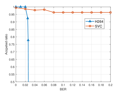
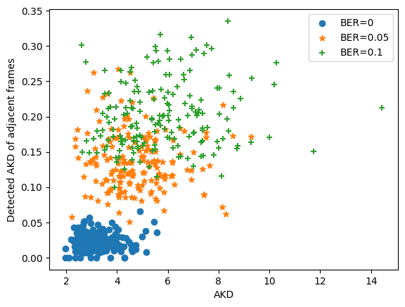
The errors in the SVC are difficult to find independently; thus, the VGG-based quality detector always achieves higher accepted ratio than 96%. Therefore, the SVC can protect the visual quality even under the wicked environment because the main appearance features are shared in advance. Thus, the VGG-based quality detector is insufficiently effective as a semantic detector. Apart from the quality of the received frame, the received video should be fluent. Meanwhile, the performance of the current frame cannot be obtained because the true current frame is unknown to the receiver in practice. Thus, the keypoints are detected again at the receiver by the trained keypoint detector, and the average distances of the detected keypoints between the adjacent frames, called detected AKD, are related to the video fluency. As shown in Fig. 7(b), the detected AKDs of the most frames are lower than 0.05 when no bit error exists and increase with BER. Compared with the 32-bit CRC code used in the conventional HARQ systems, the fluency detector is helpful to guarantee the quality of the video without any extra parity code.
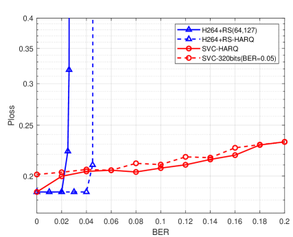
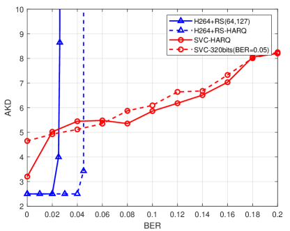
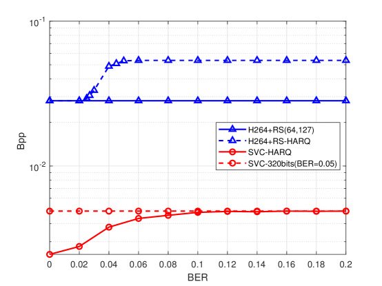
Finally, the whole SVC-HARQ framework is tested as shown in Fig. 8. The competing method, H264+RS-HARQ, first transmits 127 symbols per 64 information symbols. Then, the incremental 128 symbols are transmitted if the CRC detector finds errors. Compared with H264+RS(64, 127), H264+RS-HARQ can correct more errors and maintain its best performance when BER is no larger than 0.04. The required bits per frame of the H264+RS-HARQ increase from BER, where H264+RS(64, 127) cannot restore all the errors. When BER , the capability of the H264+RS-HARQ cannot correct the errors and its performance decreases sharply. The SVC-HARQ first transmits 160 bits per frame. Then, 160 incremental bits are transmitted if the proposed semantic detector finds errors. The SVC-HARQ can reach the best performance of SVC+RS(64, 127) when no bit error exists and becomes close to the SVC+RS(64 ,255) when BER 0.04. The AKD performance of the SVC-HARQ is not smooth when BER is between 0.02 and 0.06 because the error detection of detected AKD is not a strict method. The required bits per frame are the same as the H264+RS(64, 127) when no bit error exists and then increase with the BER. Overall, the SVC-HARQ always requires 1/12 bits per frame of the H264+RS-HARQ.
The absolute value changes of Ploss is small because the Ploss represents the whole content and expression errors only occupy a small part in the image. For example, the Ploss of the SVC-HARQ is about 0.18 when BER=0 and that is about 0.23 when BER =0.2. The AKD only concentrates on the facial expression and its change is large. Specially, the tendencies of Ploss and AKD metrics are similar. Therefore, inaccurate facial expression is the major factor for lower Ploss due to higher BER.
From the above discussion, the SVC-HARQ shows its flexibility in the bit consumption with the change in BER. Meanwhile, the SVC-HARQ can reach the best performance of the SVCs trained under different BERs as an adaptive method. However, the semantic detector can only protect the fluency of the video. A detector to find expression errors should be proposed for an important conference.
IV-D Performance of SVC-CSI
We consider frequency-selective channels to test the effectiveness of the CSI feedback. All the SVCs with CSI feedback are trained under the channels with exponential power delay profile of three paths. Each path obeys complex Gaussian distribution. Because the channel model is introduced when training, we also simulate untrained channels with five paths to test the robustness of the SVC. The testing environment is called mismatched channel environments because their statistical parameters, such as delay spread, are different from trained channels. The number of the subchannels in the frequency domain is 16. The transmit bits are modulated to 16-QAM.
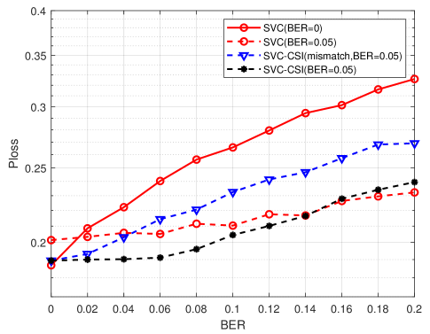
As shown in Fig. 9(a), the SVC-CSI(BER=0.05) means the average BER of the training channels is 0.05. The SVC-CSI (BER=0.05) has similar Ploss performance as SVC (BER=0.05) when BER > 0.14, and has better performance than SVC (BER=0.05) when BER <0.14. It reaches the performance of SVC (BER=0) when BER=0 because the SVC-CSI learns to protect the information according to the qualities of the channels. However, the performance of the SVC-CSI decreases more sharply under mismatched channel environments and thus SVC-CSI (mismatch) performs worse than the SVC (BER=0.05) when BER > 0.04. Overall, the CSI feedback enhances the performance when BER is low under the matched channel environments but loses its robustness under the mismatched environments.
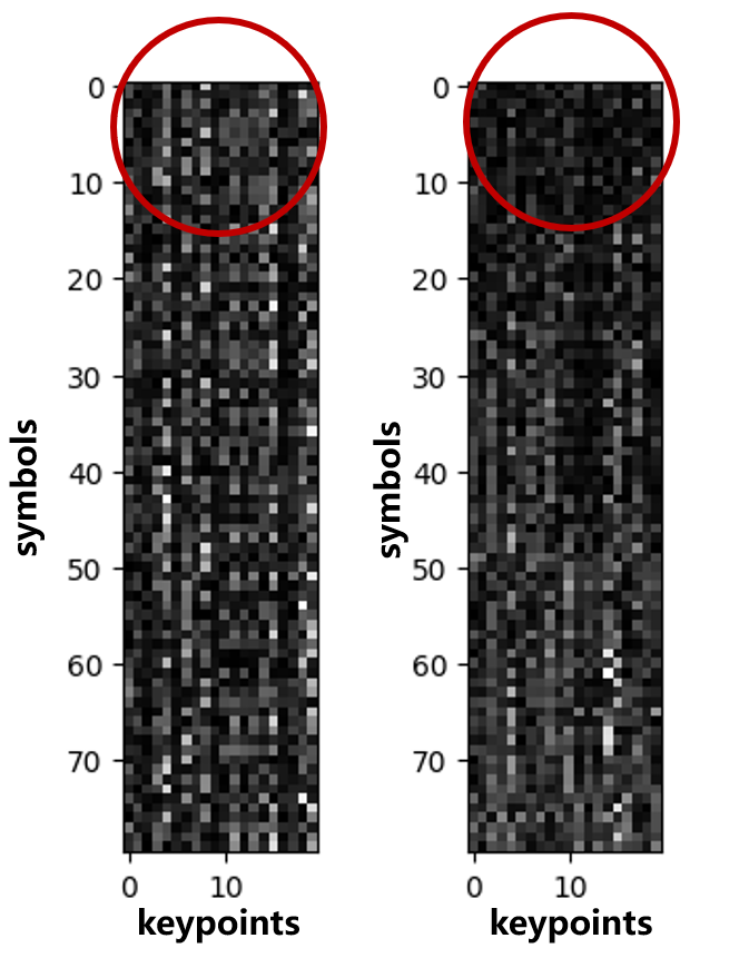
In order to visualize the impact of the CSI feedback, we replace the three dense layers at the transmitter in the technical level with one dense layer, whose input includes keypoints (20 real numbers) and output includes 80 symbols (320 bits with 4-bit quantization). In Fig. 9(b), the absolute values of trained multiplicative weights in this dense layer are shown as a gray picture, and only the weights on the right picture are trained with CSI feedback. Thus, the symbols on the right picture are usually transmitted at better channels than those on the left one due to CSI feedback. The absolute values in the circle of the right picture are larger than those of the left picture. This finding means that the transmitter learns to place more information at the better channel conditions. The SVC-CSI performs better than the SVC when BER is higher because most information is transmitted at the first several channels with lower noise power.
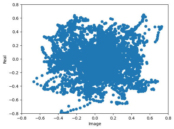
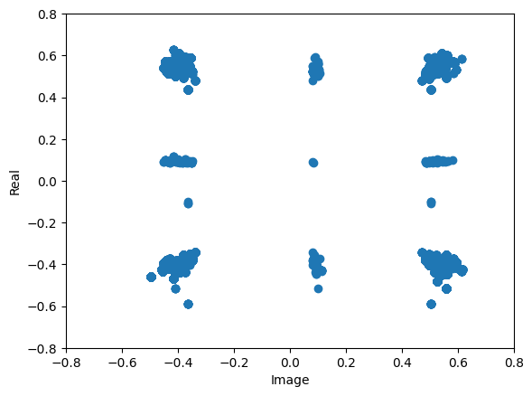
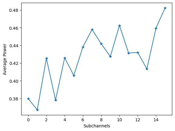
The keypoints are also transmitted as symbols directly under Rayleigh fading channels in Fig. 10. The SVC-CSI (full-resolution) learns to transmit 160 real symbols. Due to CSI feedback with 16 subchannels, the first five symbols are always transmitted under the highest SNR and the last five symbols are under the lowest SNR. The constellation points of SVC-CSI (full-resolution) are spread around in Fig. 10(a). Meanwhile, this method learns to transmit more information at better subchannels; thus, the transmit power decreases when the channel condition becomes worse as shown in Fig. 10(c). The SVC-CSI (quantized-resolution) has the same modulation method at all subchannels and its constellation points shown in Fig. 10(b) are similar to 16-QAM. In order to cope with the noise, the transmit power of the SVC-CSI (quantized-resolution) becomes larger as the channel condition becomes worse.
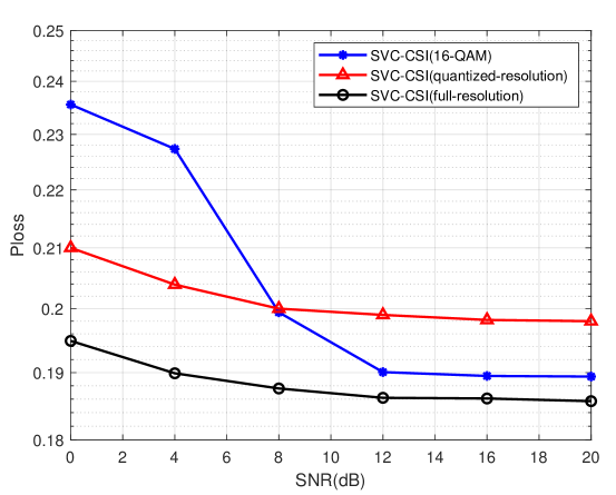
The Ploss performance of the SVC-CSI under fading channels is compared. The SVC-CSI (16-QAM) is trained to transmit 320 bits and modulated to 80 16-QAM symbols. The three methods in Fig. 11 have the same transmit resources. The SVC-CSI (full-resolution) always has best performance, but its complexity is impractical. The SVC-CSI (quantized-resolution) learns a different modulation method from 16-QAM. This method performs worse than 16-QAM when SNR 8 dB but better than 16-QAM when SNR is low. Therefore, the trained modulation of SVC-CSI (quantized-resolution) is suitable for wired environments but cannot perfectly reconstruct the frame when SNR is high.
| BER | 0 | 0.02 | 0.04 | 0.06 | 0.08 | 0.10 |
|---|---|---|---|---|---|---|
| SVC-HARQ | 0.186 | 0.199 | 0.204 | 0.205 | 0.203 | 0.207 |
| SVC-CSI-HARQ(mismatch) | 0.189 | 0.193 | 0.203 | 0.205 | 0.206 | 0.207 |
| SVC-CSI-HARQ | 0.189 | 0.190 | 0.190 | 0.191 | 0.196 | 0.206 |
The introduction of HARQ can improve the performance of the SVC-CSI under mismatched channels, and this method is called SVC-CSI-HARQ. In this method, the second transmission is trained without CSI feedback and thus robust to the varying environments. This strategy can guarantee that the SVC-CSI-HARQ under mismatched environment is not worse than SVC-HARQ. Meanwhile, SVC-CSI-HARQ performs better than SVC-HARQ under mismatched channels when 0.02 BER 0.1 because the mismatched power correlation at subchannels is slight when subchannel gain is large. In addition, the SVC-CSI-HARQ shows its superiority under the matched channels. Specially, the SVC-HARQ is slightly better than the methods with CSI feedback when BER=0 because the CSI feedback is ineffective under noiseless channels. In contrast, the CSI feedback may mislead the SVC to transmit less information at the last subchannels
V Conclusions
We have investigated semantic transmission framework for video conferencing. The knowledge of the speaker’s photos can be shared explicitly because the faces play an essential role at a conference. The three-level framework, called SVC, is established by utilizing only keypoint transmission to represent the motion of the facial expressions. The compression by the SVC only loses detailed expressions while the conventional methods reduce the resolution. Furthermore, the transmission errors in the conventional methods destroy pixels directly while those in SVC leads a changed expression.
We have also considered the impact of feedback in the SVC and designed an IR-HARQ framework called SVC-HARQ with ACK feedback. The changed expression of the error keypoints obtains nonsmooth adjacent frames. To detect semantic errors, we have developed a semantic detector, including identity classifier and fluency detection. The SVC-HARQ is flexible and it can combine the performance of the networks trained under different BERs and always reach a good performance. The CSI feedback can also enhance the performance further. The transmitted symbols or bits are sorted by SNRs at different subchannels, called SVC-CSI. The SVC-CSI learns to allocate more information at the subchannels with higher gains and performs better than the SVC without CSI feedback. However, the robustness of the SVC-CSI decreases because the channel model is exploited when training. The combination of CSI and ACK feedback can balance the performance, bit consumption, and robustness.
References
- [1] J. Bao, P. Basu, M. Dean, C. Partridge, A. Swami, W. Leland, and J. A. Hendler, “Towards a theory of semantic communication,” in 2011 IEEE Network Science Workshop. IEEE, 2011, pp. 110–117.
- [2] Z. Qin, X. Tao, J. Lu, and G. Y. Li, “Semantic communications: Principles and challenges,” arXiv preprint arXiv:2201.01389, 2021.
- [3] K. Lu, Q. Zhou, R. Li, Z. Zhao, X. Chen, J. Wu, and H. Zhang, “Rethinking modern communication from semantic coding to semantic communication,” arXiv preprint arXiv:2110.08496, 2021.
- [4] M. Sana and E. C. Strinati, “Learning semantics: An opportunity for effective 6G communications,” in IEEE Consumer Commun. Netw. Conf. (CCNC). IEEE, 2022, pp. 631–636.
- [5] H. Ye, G. Y. Li, and B. H. Juang, “Power of deep learning for channel estimation and signal detection in OFDM systems,” IEEE Wireless Commun. Lett., vol. 7, no. 1, pp. 114–117, Feb. 2018.
- [6] H. Ye, L. Liang, G. Y. Li, and B.-H. Juang, “Deep learning-based end-to-end wireless communication systems with conditional GANs as unknown channels,” IEEE Trans. Wireless Commun., vol. 19, no. 5, pp. 3133–3143, May 2020.
- [7] T. J. O’ Shea and J. Hoydis, “An introduction to deep learning for the physical layer,” IEEE Trans. Cogn. Commun. Netw., vol. 3, no. 4, pp. 563–575, Dec. 2017.
- [8] Z.-J. Qin, H. Ye, G. Y. Li, and B.-H. Juang, “Deep learning in physical layer communications,” IEEE Wireless Commun., vol. 26, no. 2, Apr. 2019.
- [9] H. He, S. Jin, C. Wen, F. Gao, G. Y. Li, and Z. Xu, “Model-driven deep learning for physical layer communications,” IEEE Wireless Commun., vol. 26, no. 5, pp. 77–83, Oct. 2019.
- [10] O. Y. Bursalioglu, G. Caire, and D. Divsalar, “Joint source-channel coding for deep-space image transmission using rateless codes,” IEEE Trans. Commun., vol. 61, no. 8, pp. 3448–3461, Jun. 2013.
- [11] D. B. Kurka and D. Gündüz, “DeepJSCC-f: Deep joint source-channel coding of images with feedback,” IEEE J. Sel. Areas Inf. Theory, vol. 1, no. 1, pp. 178–193, Apr. 2020.
- [12] E. Bourtsoulatze, D. B. Kurka, and D. Gündüz, “Deep joint source-channel coding for wireless image transmission,” IEEE Trans. Cogn. Commun. Netw., vol. 5, no. 3, pp. 567–579, Sep. 2019.
- [13] C. Lee, J. Lin, P. Chen, and Y. Chang, “Deep learning-constructed joint transmission-recognition for internet of things,” IEEE Access, vol. 7, pp. 76 547–76 561, Jun. 2019.
- [14] F. Zhai, Y. Eisenberg, and A. K. Katsaggelos, “Joint source-channel coding for video communications,” Handbook of Image Video Process., pp. 1065–1082, 2005.
- [15] Z. Weng and Z. Qin, “Semantic communication systems for speech transmission,” IEEE J. Sel. Areas Commun., Jan. 2021.
- [16] N. Farsad, M. Rao, and A. Goldsmith, “Deep learning for joint source-channel coding of text,” in Proc Int. Conf. Acoustics Speech Signal Process. (ICASSP). IEEE, 2018, pp. 2326–2330.
- [17] H. Xie, Z. Qin, G. Y. Li, and B.-H. Juang, “Deep learning enabled semantic communication systems,” IEEE Trans. Signal Process., vol. 69, pp. 2663–2675, Apr. 2021.
- [18] H. Xie and Z. Qin, “A lite distributed semantic communication system for internet of things,” IEEE J. Sel. Areas Commun., vol. 39, no. 1, pp. 142–153, 2021.
- [19] X. Kang, B. Song, J. Guo, Z. Qin, and F. R. Yu, “Task-oriented image transmission for scene classification in unmanned aerial systems,” arXiv preprint arXiv:2112.10948, 2021.
- [20] A. Siarohin, S. Lathuilière, S. Tulyakov, E. Ricci, and N. Sebe, “First order motion model for image animation,” Advances in Neural Info. Process. Syst., vol. 32, pp. 7137–7147, 2019.
- [21] T.-C. Wang, A. Mallya, and M.-Y. Liu, “One-shot free-view neural talking-head synthesis for video conferencing,” in IEEE/CVF Conf. Comput. Vision Pattern Recogn. (CVPR), 2021, pp. 10 039–10 049.
- [22] Y. Yang, C. Guo, F. Liu, C. Liu, L. Sun, Q. Sun, and J. Chen, “Semantic communications with ai tasks,” arXiv preprint arXiv:2109.14170, 2021.
- [23] M. L. B. Riediger and P. K. M. Ho, “Application of Reed-Solomon codes with erasure decoding to type-II hybrid ARQ transmission,” in Proc. Global Commun. Conf., vol. 1, Dec. 2003, pp. 55–59 Vol.1.
- [24] J. Abot, C. Olivier, C. Perrine, and Y. Pousset, “A link adaptation scheme optimized for wireless JPEG 2000 transmission over realistic MIMO systems,” Signal Process.: Image Commun., vol. 27, no. 10, pp. 1066–1078, 2012.
- [25] A. Siarohin, S. Lathuilière, S. Tulyakov, E. Ricci, and N. Sebe, “Animating arbitrary objects via deep motion transfer,” in IEEE/CVF Conf. Comput. Vision Pattern Recogn. (CVPR), 2019, pp. 2377–2386.
- [26] A. Newell, K. Yang, and J. Deng, “Stacked hourglass networks for human pose estimation,” in European conf. comput. vision. Springer, 2016, pp. 483–499.
- [27] L. Theis, W. Shi, A. Cunningham, and F. Huszár, “Lossy image compression with compressive autoencoders,” arXiv preprint arXiv:1703.00395, 2017.
- [28] J. Johnson, A. Alahi, and F.-F. Li, “Perceptual losses for real-time style transfer and super-resolution,” in European conf. comput. vision. Springer, 2016, pp. 694–711.
- [29] K. Simonyan and A. Zisserman, “Very deep convolutional networks for large-scale image recognition,” arXiv preprint arXiv:1409.1556, 2014.
- [30] T.-C. Wang, M.-Y. Liu, A. Tao, G. Liu, J. Kautz, and B. Catanzaro, “Few-shot video-to-video synthesis,” arXiv preprint arXiv:1910.12713, 2019.
- [31] W. Zhang, K. Ma, J. Yan, D. Deng, and Z. Wang, “Blind image quality assessment using a deep bilinear convolutional neural network,” IEEE Trans. Circ. Syst. for Video Techno., vol. 30, no. 1, pp. 36–47, 2018.
- [32] A. Bulat and G. Tzimiropoulos, “How far are we from solving the 2D & 3D face alignment problem? (and a dataset of 230,000 3d facial landmarks),” in Int. Conf. Comput. Vision, 2017.
- [33] A. Nagrani, J. S. Chung, and A. Zisserman, “Voxceleb: a large-scale speaker identification dataset,” arXiv preprint arXiv:1706.08612, 2017.
- [34] D. P. Kingma and J. Ba, “Adam: A method for stochastic optimization,” arXiv preprint arXiv:1412.6980, 2014.
- [35] S. B. Wicker and M. J. Bartz, “Type-II hybrid-ARQ protocols using punctured MDS codes,” IEEE Trans. Commun., vol. 42, no. 234, pp. 1431–1440, Apr. 1994.
- [36] A. Hore and D. Ziou, “Image quality metrics: PSNR vs. SSIM,” in Int. Conf. Pattern Recogn. IEEE, 2010, pp. 2366–2369.
- [37] R. Zhang, P. Isola, A. A. Efros, E. Shechtman, and O. Wang, “The unreasonable effectiveness of deep features as a perceptual metric,” in IEEE Conf. Comput. Vision Pattern Recogn. (CVPR), 2018, pp. 586–595.