[1]\textbf\textitIndex terms— #1
Design of a Reconfigurable Intelligent Surface-Assisted FM-DCSK-SWIPT Scheme with Non-linear Energy Harvesting Model ††thanks: This work was supported in part by the NSF of China under Grant 62071131, the Guangdong Basic and Applied Basic Research Foundation under Grant 2022B1515020086, the International Collaborative Research Program of Guangdong Science and Technology Department under Grant 2022A0505050070, and the Industrial Research and Development Project of Haoyang Electronic Company Ltd., under Grant 2022440002001494. (Corresponding author: Yiwei Tao.) ††thanks: Yi Fang, Yiwei Tao, and Huan Ma are are with the School of Information Engineering, Guangdong University of Technology, Guangzhou 510006, China. (e-mail: fangyi@gdut.edu.cn; taoyiwei0806@163.com; mh-zs@163.com). ††thanks: Yonghui Li is with the School of Electrical and Information Engineering, The University of Sydney, Sydney, NSW 2006, Australia (e-mail: yonghui.li@sydney.edu.au). ††thanks: Mohsen Guizani is with the Department of Machine Learning, Mohamed Bin Zayed University of Artificial Intelligence (MBZUAI), Abu Dhabi, UAE (e-mail: mguizani@ieee.org).
Abstract
In this paper, we propose a reconfigurable intelligent surface (RIS)-assisted frequency-modulated (FM) differential chaos shift keying (DCSK) scheme with simultaneous wireless information and power transfer (SWIPT), called RIS-FM-DCSK-SWIPT scheme, for low-power, low-cost, and high-reliability wireless communication networks. In particular, the proposed scheme is developed under a non-linear energy-harvesting (EH) model which can accurately characterize the practical situation. The proposed RIS-FM-DCSK-SWIPT scheme has an appealing feature that it does not require channel state information, thus avoiding the complex channel estimation. We further derive the closed-form theoretical expressions for the energy shortage probability and bit error rate (BER) of the proposed scheme over the multipath Rayleigh fading channel. In addition, we investigate the influence of key parameters on the performance of the proposed transmission scheme in two different scenarios, i.e., RIS-assisted access point (RIS-AP) and dual-hop communication (RIS-DH). Finally, we carry out various Monte-Carlo experiments to verify the accuracy of the theoretical derivation, illustrate the performance advantage of the proposed scheme, and give some design insights for future study.
Index Terms:
Reconfigurable intelligent surface, differential chaos shift keying, simultaneous wireless information and power transfer, non-linear energy-harvesting, multipath Rayleigh fading channel.I Introduction
The dramatic increase in the number of wireless devices raises higher demands on the energy consumption and reliability of wireless communication networks. Therefore, the research on new wireless techniques enabling low-power, low-cost, and high-reliability features have attracted widespread attention in recent years [1, 2, 3].
As a prestigious non-coherent technique, chaos-based communication is a key solution to meet the above demands [4, 5]. This technique uses wide-band and non-periodic chaotic signals to enhance the transmission reliability and security. In the past two decades, a myriad of chaos-based communication techniques such as chaos shift keying (CSK) [6] and differential chaos shift keying (DCSK) [7] have been intensively investigated. In particular, the DCSK schemes have become the most studied scheme due to their low hardware complexity as well as excellent anti-multipath fading and anti-jamming properties.
Recently, many variants of the DCSK scheme have been proposed to further optimize the performance. In [8], a frequency-modulated (FM) DCSK scheme has been designed to solve the problem of energy non-conservation in conventional DCSK scheme. The FM-DCSK scheme has been incorporated into ultra-wideband (UWB) communications [9, 10]. To achieve higher data rate and energy efficiency, a variety of index modulation schemes have been devised and intelligently integrated with DCSK schemes, such as code-index-modulation [11, 12, 13], carrier-index-modulation [14, 15], and multidimensional-index-modulation [16, 17, 18]. An -ary DCSK scheme has been proposed to realize higher data rate transmissions [19]. On this basis, an adaptive multiresolution -ary DCSK scheme has been conceived, which can satisfy more flexible bit error rate (BER) and higher spectrum efficiency [20]. To improve the reliability, some DCSK schemes based on multi-input and multi-output (MIMO) techniques have been developed. In [21], an analog space-time-block-code (STBC) DCSK scheme not requiring channel state information (CSI) has been conceived. This scheme constructs a space-time block pattern of the transmitted signal to avoid channel estimation. In [22], a DCSK scheme with transmit diversity has been conceived, which achieves full diversity by optimizing the space-time block pattern. Although large-scale antenna array deployment can improve the reliability of wireless communication networks, multiple radio frequency (RF) links lead to higher energy consumption and hardware cost. Moreover, some powerful error-correction codes have been incorporated into DCSK systems to further improve the robustness against fading and noise [23].
For the sake of reducing energy consumption, low-power devices have been applied in many wireless networks, especially wireless sensor networks (WSNs) [24] and wireless personal area networks (WPANs) [25]. These devices do not have external battery. To realize energy self-sufficiency, simultaneous wireless information and power transfer (SWIPT) technique has been conceived [26]. This technique can provide power to energy-limited devices when transmitting information, which reduces the energy consumption of network nodes and extends the operating time of devices. Owing to these advantages, SWIPT has been employed in various communication scenarios, such as multi-antennas scenarios [27], cooperation communication scenarios [28], and non-orthogonal multiple access (NOMA) scenarios [29].
Typically, the conventional SWIPT systems always need synchronization and channel estimation [30]. In recent years, the SWIPT has been combined with DCSK scheme so as to address the synchronization problem and boost the energy efficiency [31, 32, 33]. Nonetheless, there are still many challenges in the practical application of the SWIPT technique. To be specific, when the distance between the transmitter and receiver is relatively large, the efficiency of wireless power transfer will be dramatically reduced by the large-scale path loss. To overcome the above weakness, the integration of SWIPT technique with emerging communication technologies, such as reconfigurable intelligent surface (RIS), has been explored [34].
In fact, RIS is a passive metamaterial surface consisting of a large number of low-cost reflecting elements [35, 36, 37]. It can control each reflecting element to change the phase of the input signal, thus resisting the channel interference and fading. Besides, the deployment of RIS can effectively enhance the signal strength, thereby compensating for the large-scale path loss caused by long distances [38]. Unlike the conventional multi-antennas and relay schemes, RIS does not require additional power to amplify and forward the signal, which is more energy efficient and environmentally friendly [39]. In addition, as a passive device, RIS works in a full duplex mode without generating extra noise and self-interference [40]. As such, RIS has been considered as a promising solution to reduce the energy consumption and cost of wireless communication networks.
Based on the above background, we put forth an RIS-assisted FM-DCSK SWIPT scheme in this paper. This scheme intelligently integrates the RIS with FM-DCSK scheme to effectively compensate for the energy loss caused by large scale path loss. As the first work on RIS-assisted non-coherent DCSK scheme, we establish the RIS-assisted DCSK transmission framework which adopts a blind-channel-aided design methodology that does not require CSI. Moreover, we take the multipath Rayleigh fading channel, which is commonly used in DCSK scheme [15, 16, 17], as an example to illustrate the channel model in RIS-AP scenario and the cascaded channel model in RIS-DH scenario. In addition, all the existing DCSK SWIPT schemes only consider the linear energy harvesting (EH) model [31, 32, 33], but not the non-linear EH model. However, in the practical EH circuit, the RF energy conversion efficiency increases with the input power, but the maximum harvested energy is limited due to its saturation effect [41, 42, 43]. Hence, in this paper, a non-linear EH model is considered in the design of RIS-FM-DCSK-SWIPT scheme for the first time, which can more accurately reflect the EH saturation effect compared with the linear counterpart. Furthermore, we investigate the performance of the proposed RIS-FM-DCSK-SWIPT system in two different deployment scenarios so as to verify its merit. For clarity, the main contributions of this paper are outlined as follows.
1) We establish an RIS-assisted non-coherent DCSK framework. Based on this framework, we adopt a non-linear EH model to develop an RIS-assisted FM-DCSK SWIPT scheme, called RIS-FM-DCSK-SWIPT scheme, which can improve the efficiency of power transfer and the reliability of information transmission. The above features make the proposed scheme particularly suitable for low-power and low-cost wireless communication networks.
2) We analyze the BER performance and energy shortage probability of the proposed scheme over the multipath Rayleigh fading channel, in two different deployment scenarios of RIS-assisted DCSK SWIPT scheme, i.e., access point (AP) and dual-hop communication (DH) scenarios. We further derive the corresponding closed-form approximate BER and energy shortage probability expressions.
3) Simulation results not only verify the accuracy of the closed-form approximate BER and energy shortage probability expressions of the proposed RIS-FM-DCSK-SWIPT scheme, but also illustrate that the proposed scheme can achieve desirable performance gains over the existing DCSK-SWIPT schemes. Furthermore, we present some new design insights for the proposed RIS-FM-DCSK-SWIPT scheme based on the simulations.
The remainder of this paper is structured as follows. Section II describes the system model of the proposed RIS-FM-DCSK-SWIPT scheme. Section III analyzes the energy shortage probability and BER of the proposed scheme. In Section IV, the numerical results are discussed and analyzed to evaluate the performance of the proposed scheme. Finally, conclusion is drawn in Section V.
II System Model
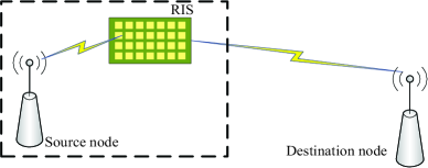
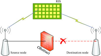
In this section, we describe the system model and transmission mechanism of the proposed RIS-FM-DCSK-SWIPT scheme. As shown in Fig. 1, two deployment scenarios of RIS are considered. In the first scenario (i.e., Fig. 1(a)), the RIS is regraded as an access point (AP) of the source node to assist information transmission, referred to as RIS-AP. In the second scenario (i.e., Fig. 1(b)), the direct link between the source node and the destination node is blocked, hence the RIS is regraded as a relay to realize a DH communication, referred to as RIS-DH. More specifically, in the RIS-DH scenario, the signal is sent from the source to the RIS, and the RIS immediately reflects the signal to the destination.
II-A Principle of the Proposed RIS-FM-DCSK-SWIPT
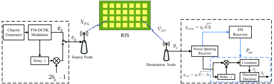
Fig. 2 illustrates the block diagram of the transceiver for the proposed RIS-FM-DCSK-SWIPT scheme. In the transmitter, an FM-DCSK modulation scheme is used to transmit information bits.111Since the chaotic signal is a non-periodic signal, the energy per symbol of DCSK scheme is not constant. To solve this problem, the FM-DCSK scheme was adopted in this paper to obtain more stable performance for the proposed scheme. Especially, we consider the low-pass equivalent model of FM-DCSK scheme for the theoretical design and simulation-level validation in this paper [44, 45]. In actual implementation, the FM bandwidth setting needs to be adjusted according to the specific application requirements. Especially, is the information bit, carried by the - RIS-FM-DCSK-SWIPT symbol. At the begining, a second-order Chebyshev polynomial function is used to generate a chaotic signal with a length of . The chaotic signal is then input into the FM-DCSK modulator to produce an FM chaotic signal , where the spreading factor () of the RIS-FM-DCSK-SWIPT scheme is . Next, we uniformly divide the transmission symbol duration into two parts. In the first part, we use as the reference signal. In the second part, if , information-bearing signal is a replica of , otherwise it becomes an inverted version of . To express more clearly, the - transmission signal of the RIS-FM-DCSK-SWIPT scheme can be written as
| (1) |
Finally, the source spends the power to transmit the modulated signal . As in other RIS-related works [36, 37, 39], we assume there is no direct link between the source and the destination in both RIS-AP and RIS-DH scenarios. Hence, the transmitted signal is first sent to the RIS, and then immediately reflected to the destination by the reflecting elements of the RIS.
RIS can offset the channel phase by adjusting the phase of its reflecting elements to maximize the received signal-to-noise ratio (SNR), thereby improving the performance of wireless communications. However, the RIS-assisted communication schemes always need to obtain precise CSI. Since the channel environment of RIS is quite complicated, and channel estimation requires additional cost (e.g., hardware and energy consumption). To reduce the implementation complexity, we develop a new design for the proposed RIS-FM-DCSK-SWIPT scheme under the condition of a blind channel. In this case, the phases of the channels are unknown and thus the RIS cannot change the signal phase or changes the phase randomly. Thereby, in this paper, the RIS cannot be used to maximize the received SNR. Without loss of generality, we assume that the phase of each reflecting element on RIS is zero [37, 46, 47, 48].
II-A1 RIS-AP
In this scenario, we assume that the transmitter is close enough to the RIS such that the path loss and multipath fading for the link can be neglected [36, 47, 49].222It is worth noting that the link in this scenario is also affected by some other factors such as spill-over loss, taper loss, and blockage-free loss [50]. Nevertheless, in this paper, we mainly focus on the impact of path loss and multipath fading on the system performance in order to offer a fundamental basis for future theoretical investigation of RIS-assisted DCSK systems. Let denote the number of reflecting elements in the RIS. The transmitted signal passes through a wireless channel, and the received signal is obtained as
| (2) |
where is the distance between RIS and destination, is the path loss coefficient, is the number of paths in a multipath fading channel, and represent the fading coefficient and delay of the - path on the - reflecting element for the link between the RIS and destination (i.e., ), respectively. Besides, is the additive Gaussian white noise (AWGN), where denotes the complex Gaussian distribution with mean of zero and variance of .
II-A2 RIS-DH
Due to the obstruction of obstacle, the RIS is deployed in a certain position between the source and the destination to assist the information transmission. Therefore, the path loss and wireless fading for both links and should be considered, and the received signal in this scenario can be written as
| (3) |
where denotes the distance between source and RIS, is the number of paths in a multipath fading channel, and represent the fading coefficient and delay of the - path on the - reflecting element for the link , respectively. It is worth noting that RIS is a passive device which only reflects the signal, thus the noise from RIS can be neglected.
Afterwards, the received signal is divided into two parts by the power splitting receiver. We employ a power splitting (PS) approach for EH that simultaneously guarantees energy supply and information transmission in the energy-limited devices. In detail, one part is used for energy harvesting, and the collected energy is used for the other part to demodulate the information bits. We define and as the two received sub-signals for EH and information demodulation, respectively, where . Especially, represents the RIS-AP scenario, while represents the RIS-DH scenario. To be specific, the two received sub-signals can be expressed as
| (4) |
| (5) |
Here, is defined as the scaling factor of power splitting, is the AWGN in the information-demodulation procedure. To estimate the information bit, we correlate with its delayed version so as to get a decision metric , as follows
| (6) |
where and denote the real-part extraction and conjugate operations, respectively. Finally, the - information bit is estimated as
| (7) |
II-B Non-Linear EH Model
In most of the existing literature [31, 32, 33], a linear EH model is considered. In this model, , where and denote the output power and input power, respectively, and is the energy conversion factor. Moreover, the output power of the EH receiver has a linear relationship with its corresponding input power. However, due to the saturation effect of EH, the output power will not always increase linearly with the input power of the circuit. In actual implementations, the output power first increase with the input power and then gradually reaches a saturated value. Hence, this linear EH model cannot accurate characterize the EH situation of the practical circuit. In this paper, we consider a non-linear EH model [41, 42], which is more consistent with practical SWIPT applications. This model can be mathematically described as
| (8) |
where is the maximum harvested power in the case of EH saturation, and are parameters that reflect the characteristics of the EH circuit. By adjusting these parameters, different EH circuits can be set up.
II-C Channel Model
In this paper, we consider a multipath Rayleigh fading channel.333We assume that the reflecting elements are placed with horizontal and vertical inter-element distances equal to or greater than the signal wavelength. In this case, the signals coupling relationship between the reflecting elements can be neglected and the fading channel can be approximately considered as an i.i.d fading channel [51, 52]. In future, we will consider more realistic channel models [53] for RIS-assisted communication system. In this channel, the channel coefficient keeps constant during each symbol duration, but varies over different symbol durations. Under this assumption, we have and , where , , and denotes the Euclidean norm. In addition, we assume that the delays of all reflecting elements in the RIS are the same, i.e., . For a large , according to the central limit theorem (CLT) [36, 54, 55], the received signals in the RIS-AP scenario can be expressed as
| (9) |
where , . Similarly, the received signals in the RIS-DH scenario can be expressed as
| (10) |
It is worth noting that for the RIS-DH scenario, the channel constructed by the two links and can be considered as a cascaded channel [39]. Hence, for the cascaded channel, the number of paths is , the path delay is ,, and the channel coefficient is , where and .
III Performance Analysis
In this section, the energy shortage probabilities of the RIS-FM-DCSK-SWIPT scheme in two deployment scenarios are analyzed over a multipath Rayleigh fading channel. Moreover, the theoretical BER expressions of the proposed scheme are derived. In the analysis, we assume that the largest path delay is much smaller than the symbol duration, i.e., [17]. As such, the inter-symbol interference (ISI) can be neglected. Without loss of generality, we assume that the channel gains are unequal, i.e., and .
III-A Energy Shortage Probability
In general, energy shortage occurs when the output power of the EH receiver is less than the power required for the demodulation of information bit.
III-A1 RIS-AP
According to (4) and (9), we can calculate the input power in in the RIS-AP scenario, as follows
| (11) |
Subsequently, substituting (11) into (8) yields the output power of the EH receiver, i.e.,
| (12) |
Thus, the energy shortage probability is calculated as
| (13) | ||||
For a large , we have . Hence, follows the chi-square distribution with degrees of freedom, i.e., . Under this condition, the probability density function (PDF) of can be expressed as [16, 20, 33]
| (14) |
where is defined as the - channel gain (i.e., ), and is defined as
| (15) |
Thus, the energy shortage probability can be finally formulated as
| (16) |
where
| (17) |
III-A2 RIS-DH
The energy shortage probability in the RIS-DH scenario is calculated as
| (18) | ||||
where is the output power of the EH receiver in the RIS-DH scenario. Since both the random variables and obey the same complex Gaussian distribution, the analysis method in the RIS-AP scenario can be applied to this scenario. Therefore, the closed-form expression of the energy shortage probability is given by
| (19) |
where , , and
| (20) |
III-B BER Analysis
In RIS-FM-DCSK-SWIPT scheme, the overall BER is related to the energy shortage probability and the BER for the information demodulation. In other words, the information demodulation can be only operated when the energy is sufficient; otherwise, the demodulator can no longer work. Therefore, the expression of the overall BER can be written as
| (21) |
where is the BER for the information demodulation and is the energy shortage probability. According to the CLT, considering that the decision metric obeys a Gaussian distribution, the Gaussian approximation can be used to derive the theoretical BER expression [15, 56, 57]. In this sense, can be formulated as
| (22) |
Without loss of generality, we assume that the information bit equals “” in the following analysis.
III-B1 RIS-AP
According to (5), (6), and (9), we can express the decision metric in the RIS-AP scenario as
| (23) |
where represents the overall noise, . We define , , , , where denotes an imaginary unit. Exploiting the above parameters, (23) can be simplified as
| (24) |
where and . Afterwards, the mean and variance of the decision metric can be derived as
| (25) |
| (26) |
According to (22), (25), and (26), can be calculated as
| (27) |
We define as the instantaneous SNR at the receiving end, which can be given by
| (28) |
Hence, (27) can be further expressed by
| (29) |
where the PDF of is
| (30) |
is the average SNR of the - path, and is defined as
| (31) |
To obtain the closed form of (29), we calculate the integral using the Gauss-Hermite quadrature approach [58], whose formula can be written as
| (32) |
Hence, is the number of sample points used for approximation, and its value determines the accuracy of the approximation. Moreover, is the - zero point of the Hermite polynomial , represents the - associated weight, i.e.,
| (33) |
Besides, is the remaining term, and its value decreases to zero as tends to infinity. By setting and perform some mathematical operations with respect to (29), one can obtain a formula similar to (32), as
| (34) |
Then, exploiting the Gauss-Hermite quadrature formula given in (32), the approximate closed-form BER expressions in (29) can be obtained as
| (35) |
The values of and are given in [58, Table (25.10)]. In conclusion, substituting (16) and (35) into (21), one can get the approximate closed-form expression of the overall system BER in the RIS-AP scenario over a multipath Rayleigh fading channel.
III-B2 RIS-DH
Similarly, according to (5), (6), and (10), the decision metric in the RIS-DH sceiario can be written as
| (36) |
Let , (36) reduces to
| (37) |
Furthermore, The mean and the variance of the decision metric can be derived as
| (38) |
| (39) |
Combining (22), (38), and (39), the BER for the information demodulation during demodulation can be yielded as
| (40) |
Let denotes the instantaneous SNR at the receiving end, becomes
| (41) |
Since and obey the same distribution, the PDF of can be also obtained using (30). Afterwards, the expression of can be given by
| (42) |
Similarly, by utilizing the Gauss-Hermite formula of (32), one can also obtain the approximate closed-form expression of (42) as
| (43) |
Finally, exploiting (19), (21), and (43), the approximate closed-form expression of the overall system BER in the RIS-DH scenario over a multipath Rayleigh fading channel can be promptly derived.
IV Numerical results and discussions
In this section, the numerical results of energy shortage probability and BER are evaluated for the proposed RIS-FM-DCSK-SWIPT scheme. Without loss of generality, we consider the following channel parameters in simulations. In the RIS-AP scenario, the number of paths , the channel gains , , , and the multipath delays for the link are , , . In the RIS-DH scenario, the number of paths , the channel gains , , , , the multipath delays for the link are , , and the multipath delays for the link are and . Besides, we assume that and have equal variances (i.e., ). Unless otherwise stated, the transmitted power is set to [31]. Moreover, the parameters of the non-linear energy harvesting model are set to , and [42]. We also assume that the energy cost of the information demodulation is .
IV-A EH Performance of the Proposed RIS-FM-DCSK-SWIPT Scheme
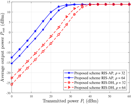
Fig. 3 shows the relationship between the average output power of EH receiver and transmitted power in the proposed RIS-FM-DCSK-SWIPT scheme under the non-linear EH model. In general, the RF energy conversion efficiency increases with the input power, but the maximum harvested energy is limited due to the saturation effect of the EH. As seen from this figure, the output power of the EH receiver first increases and then gradually approaches a saturated value. Obviously, the EH model adopted in this paper well matches with the practical EH applications and can reflect the performance of the proposed RIS-FM-DCSK-SWIPT scheme more accurately. In addition, Fig. 3 demonstrates the effect of the number of reflecting elements (i.e., ) on the output power. Especially, in the RIS-AP scenario, when the output power is , the proposed scheme with has a gain in transmitted power over that with . Similar observations can be also obtained in the RIS-DH scenario.
IV-B Energy Shortage Performance of the Proposed RIS-FM-DCSK-SWIPT Scheme
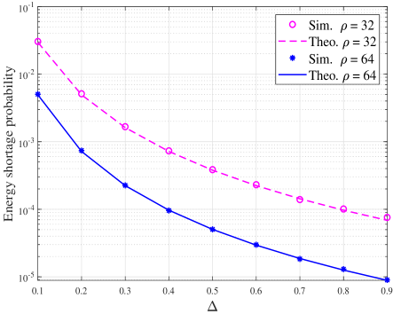
For the energy shortage probabilities of the proposed RIS-FM-DCSK-SWIPT scheme in the RIS-AP scenario, Fig. 4 compares the theoretical and simulated results. It is obvious that the simulated results match well with the theoretical results derived in (16). Moreover, we explore the effect of the number of reflecting elements (i.e., ) and the scaling factor of power splitting (i.e., ) on the energy shortage probability. As expected, increasing or leads to a decrease in the energy shortage probability. This is because that more energy will be transmitted to the EH receiver when increasing and (as noticed in (11)).
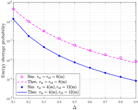
In the RIS-DH scenario, Fig. 5 shows the energy shortage probabilities of the proposed RIS-FM-DCSK-SWIPT scheme versus the scaling factor of power splitting , where the distance parameters are set to and , . This figure also verifies the accuracy of the theoretical expression (19). We also observe that the deployment location of the RIS between the source and destination has some impact on the energy shortage probability. For instance, the proposed RIS-FM-DCSK-SWIPT scheme with and has a lower energy shortage probability than that with .
IV-C BER Performance of the Proposed RIS-FM-DCSK-SWIPT Scheme
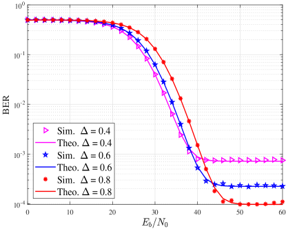
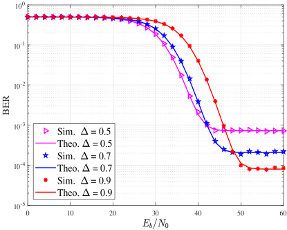
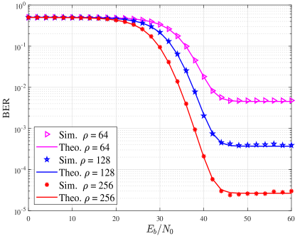
From Fig. 6(a) to Fig. 7(b), we present the theoretical and simulated BER curves of the proposed RIS-FM-DCSK-SWIPT scheme with different and over a multipath Rayleigh fading channel. We can find that the simulated results are consistent with the theoretical results, which demonstrate the correctness of BER analysis. Besides, the BER performance of the proposed scheme has an error floor, which is caused by the energy shortage.
As shown in Fig. 6(a), increasing can lower the error floor of the proposed scheme in the RIS-AP scenario. The above phenomenon is due to the fact that as the proportion of energy harvesting signals increases, the energy shortage probability reduces. However, increasing also reduces the anti-noise ability of proposed RIS-FM-DCSK-SWIPT scheme. For instance, the proposed scheme with has a gain compared to that with at a BER of . Although increasing can improve the energy shortage probability, the proportion of information demodulated signals is reduced simultaneously. Hence, the proposed scheme with a large it not able to exhibit competitive performance in the low SNR region. Also, we can observe similar results from Fig. 7(a) in the RIS-DP scenario.
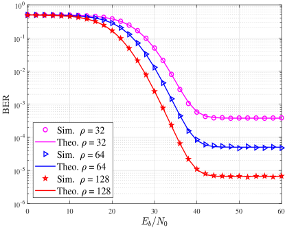
We investigate the relationship between and the BER of the proposed RIS-FM-DCSK-SWIPT scheme, as shown in Fig. 6(b) and Fig. 7(b). As expected, the BER performance of the proposed RIS-FM-DCSK-SWIPT scheme improves with the increase of . For example, referring to Fig. 6(b), the proposed scheme with has a gain over that with at the BER of . Additionally, a relatively larger can help reduce the error floor. As increases, the transmitted signal is reflected by more reflecting elements to the receiver, thereby enhancing the signal strength at the destination. Likewise, similar conclusion can be drawn in Fig. 7(b). One should strike a tradeoff between the BER performance and the parameter (or ) for the proposed scheme in order to satisfy the diverse transmission requirements in practical applications.
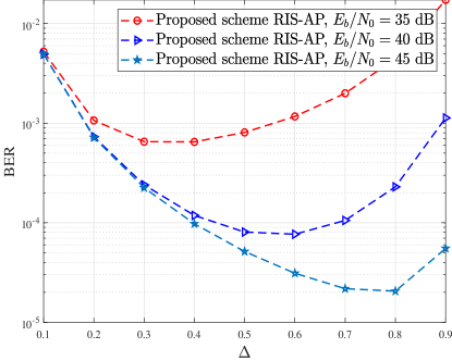
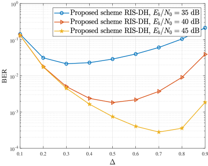
Fig. 8 shows the effect of on the BER performance of the proposed RIS-FM-DCSK-SWIPT scheme over a multipath Rayleigh fading channel, when SNRs equal , , and . We can easily observe that as increases, the BER performance of the proposed scheme has an optimal value . According to (21), the BER performance of the proposed scheme is not only related to the energy shortage probability but also related to the error probability of information demodulation. When , only a few proportion of the received signals is used for energy harvesting, thus there is not enough energy to demodulate the information. In this phase, the BER performance of the proposed scheme is mainly determined by the energy shortage probability. However, when , only a low proportion of the received signals is used to demodulate the information, which leads to a deterioration in BER performance. As such, in this phase, the BER performance of the proposed scheme is mainly determined by the error probability of information demodulation. Moreover, the optimal BER corresponds to a power splitting factor that varies with the SNR. For instance, the optimal is at a SNR of , while the optimal is at a SNR of , as shown in Fig. 8(a). The noise in the received signal decreases with the increase of SNR, hence a high proportion of the received signal is allowed to be used for energy harvesting. This not only improves the energy shortage probability but also ensures a lower error probability of information demodulation. In conclusion, the value of can be adjusted according to the variation of channel state so as to obtain the optimal BER performance.
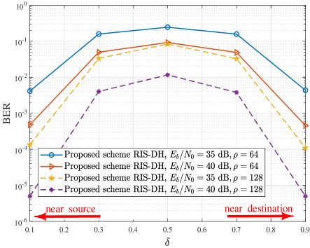
In Fig. 9, we further investigate the relationship between the deployment location of RIS and the BER performance of the proposed scheme in the RIS-DH scenario. For convenience, is defined as the scaling factor of distance, where and . It is interesting to find that the proposed scheme can obtain optimal BER performance when the deployment location of the RIS is near either the source or destination in the RIS-DH scenario. In contrast, the BER performance is worst when the deployment location of the RIS is in the center between the source and destination (i.e., ). This is because in the RIS-DH scenario, the path loss is maximum when . In this case, the receiver has the smallest received SNR according to (41). Hence, the deployment location of RIS needs to be carefully arranged for the sake of achieving the maximum performance gain.
IV-D Performance Comparison between the Proposed RIS-FM-DCSK-SWIPT Scheme and Existing Counterparts
To further illustrate the superiority of our proposed RIS-FM-DCSK-SWIPT scheme, we compare the proposed scheme with other existing DCSK-SWIPT schemes in terms of EH performance, energy shortage probability and BER performance. First, we compare the EH performance and energy shortage probability of the proposed RIS-FM-DCSK-SWIPT scheme with those of the MISO-FM-DCSK-SWIPT scheme [30], where the number of antennas (i.e., ) is set to and . In addition, we include the FM-DCSK-SWIPT scheme [8] as a fundamental benchmark.
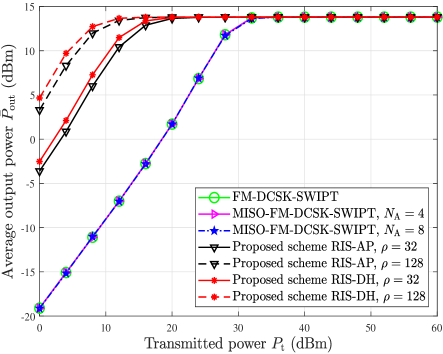
As shown in Fig. 10, we can find that with the same transmitted power, the average output power of our proposed RIS-FM-DCSK-SWIPT scheme is significantly higher than that of the MISO-FM-DCSK-SWIPT and FM-DCSK schemes. For instance, the proposed RIS-FM-DCSK-SWIPT (AP) scheme with has dB gain compared with the MISO-FM-DCSK-SWIPT and FM-DCSK schemes at a transmitted power of . Moreover, one can observe that the proposed RIS-FM-DCSK-SWIPT (DH) scheme with achieves dB gain over the MISO-FM-DCSK-SWIPT and FM-DCSK schemes at a transmitted power of . This indicates that our proposed RIS-FM-DCSK-SWIPT scheme has a higher efficiency of power transfer. In addition, the average output power of the EH receiver is related to the number of fading paths and the transmitted power of each antenna (i.e., ). Although increasing can increase the number of transmission paths, the transmitted power of each antenna becomes smaller simultaneously. Thereby, one can find that the average output power curves of the MISO-FM-DCSK-SWIPT scheme keeps the same for different values of (i.e., ).444The MISO-FM-DCSK-SWIPT scheme reduces to an FM-DCSK-SWIPT schema when the number of transmitted antennas .
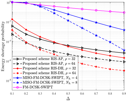
Fig. 11 demonstrates the advantages of the proposed RIS-FM-DCSK-SWIPT scheme in terms of energy shortage probability. As observed, for a target energy shortage probability of , the minimum value of that can be set in the RIS-FM-DCSK-SWIPT (AP) scheme with (i.e., ) is , while the minimum value of that can be set in the MISO-FM-DCSK-SWIPT scheme with (i.e., ) is . Similar results are also shown in RIS-FM-DCSK-SWIPT (DH) scheme. Consequently, with respect to the MISO-FM-DCSK-SWIPT scheme, the RIS-FM-DCSK-SWIPT scheme has a smaller , which indicates that more proportion of the received signals can be used for demodulation. This can improve the information transmission reliability over multipath Rayleigh fading channels.
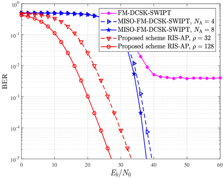
Also, one can clearly observe from Fig. 12 that the proposed RIS-FM-DCSK-SWIPT (AP) scheme with has a gain of compared to the MISO-FM-DCSK-SWIPT scheme with at a BER of , which significantly outperforms the FM-DCSK-SWIPT scheme. Although the MISO-FM-DCSK-SWIPT scheme can improve its BER performance by increasing the number of antennas, the cost and complexity will also increase. On the contrary, the proposed RIS-FM-DCSK-SWIPT (AP) scheme can also improve the BER performance by increasing the number of low-cost passive reflecting element. Based on the above discussion, the proposed scheme possesses desirable benefits of more reliable BER and lower hardware cost with respect to the MISO-FM-DCSK-SWIPT scheme.
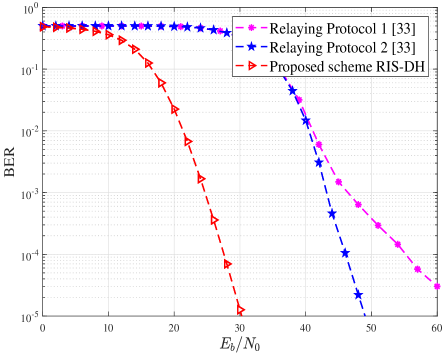
On the other hand, considering the RIS-DH scenario, we compare the BER performance of the proposed RIS-FM-DCSK-SWIPT (DH) scheme with that of the buffer-aided DCSK-SWIPT relay scheme [33] in Fig. 13. To ensure the fairness of the comparison, we assume that a non-linear EH model is used in the buffer-aided DCSK-SWIPT relay scheme. It can be seen that the proposed scheme has a great advantage in terms of BER performance compared to the two relaying protocols in [33]. Furthermore, the proposed RIS-FM-DCSK-SWIPT (DH) scheme does not require additional power to forward the source information, which remarkably reduces the energy cost in transmission.
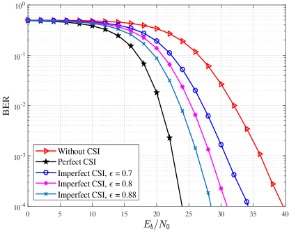
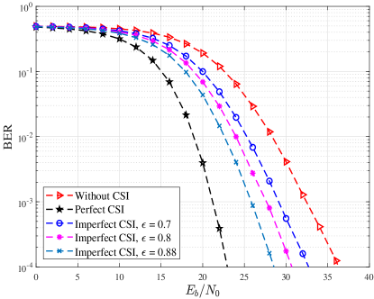
Finally, Fig. 14 shows the BER performance of the proposed RIS-FM-DCSK-SWIPT scheme in the cases of without CSI (i.e., non-coherent case), with imperfect CSI and perfect CSI over a multipath fading channel, in which the channel gains of all paths are identical. In practical applications, perfect CSI is unavailable at the receiver due to the limitations of the channel estimation algorithms and modules. According to [59, 60], in the imperfect CSI scheme, the estimated channel coefficient can be modeled as , where is the actual channel coefficient, denotes the channel correlation coefficient, and is a complex Gaussian variable with zero mean and unit variance. It is worth noting that although there are a variety of related works on RIS channel estimation, most of existing estimation algorithms are proposed based on the assumption of single-path fading channel [61, 62]. The design of RIS channel estimation algorithms over multipath fading channels is a very challenging problem, which deserves further investigation [63]. Moreover, the RIS cannot adjust the component signal phase of each path separately because these component signals passing through the multipath fading channel cannot be distinguished from one another. Therefore, the RIS can only adjust the received signal phase according to the CSI of the strongest path over the multipath fading channel [64].
Based on above setting, one can observe from Fig. 14 that the RIS-FM-DCSK-SWIPT scheme with imperfect CSI has a gain of compared to the proposed scheme without CSI at a BER of in the RIS-AP scenario, while the RIS-FM-DCSK-SWIPT scheme with imperfect CSI has a gain of compared to the proposed scheme without CSI at a BER of in the RIS-DH scenario. One can find that the scheme with perfect/imperfect CSI improves the BER performance compared to the scheme without CSI. However, the scheme with perfect/imperfect CSI suffers from higher energy consumption and complexity than the scheme without CSI. To quantify the complexity of channel estimation, we only consider the computational complexity for simplicity. The computational complexity of DCSK modulation is [16, 18]. Here, we use a low-complexity RIS channel estimation algorithm as a benchmark, the computational complexity of channel estimation algorithm is [64]. Hence, one can get that the computational complexity of the schemes with perfect/imperfect CSI and the proposed scheme without CSI are and , respectively. Taking the parameters in Fig. 14 as an example, the computational complexity of the scheme with perfect/imperfect CSI is higher than that of the proposed scheme without CSI.555The computational complexity loss of the scheme with perfect/imperfect CSI compared to the proposed scheme without CSI is calculated by . In addition, the hardware complexity and energy consumption of the scheme with perfect/imperfect CSI will be higher compared with the proposed scheme without CSI.
In summary, the proposed non-coherent scheme and the scheme with perfect/imperfect CSI have their own advantages and disadvantages in terms of complexity and BER performance. However, for the low-power and low-cost wireless communication systems (e.g., DCSK system), it is important to maintain the low-complexity advantage when the designed system achieves a target BER. According to the simulation results in Figs. 1013, one can find that the proposed non-coherent RIS-FM-DCSK-SWIPT scheme has significant advantages over the existing DCSK-SWIPT scheme in terms of EH performance and BER performance. This indicates that the proposed RIS-FM-DCSK-SWIPT scheme can fully meet the reliability and energy efficiency requirements of existing non-coherent communication systems. Therefore, compared to the scheme with perfect/imperfect CSI, the proposed non-coherent scheme can strike a better tradeoff between the complexity of BER performance, and hence can be considered as a more promising alternative for the low-power and low-cost wireless communication applications.
V Conclusion
In this paper, we have developed an RIS-assisted FM-DCSK SWIPT scheme under a non-linear EH model, which can achieve high-efficient power transfer and high-reliable information transmission. The proposed scheme has intelligently incorporated RIS into the DCSK-SWIPT scheme, which greatly enhances the performance of the conventional DCSK-SWIPT scheme. In particular, a blind-channel approach has been employed. This approach maintains the advantage of non-coherent chaotic modulation that does not require channel estimation, thus significantly reducing energy consumption and hardware cost. Moreover, we have considered two deployment scenarios of the RIS, i.e., RIS-AP and RIS-DH, in the system design. We have also carefully analyzed the closed-form theoretical energy shortage probabilities and BERs of the proposed scheme in both the RIS-AP and RIS-DH scenarios over the multipath Rayleigh fading channel. Simulated results well match with our theoretical derivations. Furthermore, we have illustrated the properties of the proposed RIS-FM-DCSK-SWIPT scheme via investigating the impact of critical parameters on the system performance. It has also been demonstrated that the proposed RIS-FM-DCSK-SWIPT scheme is superior to existing DCSK-SWIPT scheme. Thanks to the aforementioned benefits, the proposed scheme can be regarded as a competitive transmission solution for low-power and low-cost wireless communication networks.
References
- [1] J. Yuan, Y. C. Liang, J. Joung, G. Feng, and E. G. Larsson, “Intelligent reflecting surface-assisted cognitive radio system,” IEEE Trans. Commun., vol. 69, no. 1, pp. 675–687, Jan. 2021.
- [2] S. N. Daskalakis, J. Kimionis, A. Collado, G. Goussetis, M. M. Tentzeris, and A. Georgiadis, “Ambient backscatterers using FM broadcasting for low cost and low power wireless applications,” IEEE T. Microw. Theory., vol. 65, no. 12, pp. 5251–5262, Dec. 2017.
- [3] Q. Wu, X. Guan, and R. Zhang, “Intelligent reflecting surface-aided wireless energy and information transmission: an overview,” P. IEEE, vol. 110, no. 1, pp. 150–170, Jan. 2022.
- [4] G. Kaddoum, “Wireless chaos-based communication systems: A comprehensive survey,” IEEE Access, vol. 4, pp. 2621–2648, May 2016.
- [5] Y. Fang, G. Han, P. Chen, F. C. M. Lau, G. Chen, and L. Wang, “A survey on DCSK-based communication systems and their application to UWB scenarios,” IEEE Commun. Surv. Tutor., vol. 18, no. 3, pp. 1804–1837, May 2016.
- [6] H. Dedieu, M. P. Kennedy, and M. Hasler, “Chaos shift keying: modulation and demodulation of a chaotic carrier using self-synchronizing Chua’s circuits,” IEEE Trans. Circuits Syst. II, vol. 40, no. 10, pp. 634–642, Oct. 1993.
- [7] G. Kolumbán, B. Vizvári, W. Schwarz, and A. Abel, “Differential chaos shift keying: A robust coding for chaos communication,” Proc. NDES, Seville, Spain, pp. 88–92, 1996.
- [8] M. P. Kennedy, G. Kolumban, G. Kis, and Z. Jako, “Performance evaluation of FM-DCSK modulation in multipath environments,” IEEE Trans. Circuits Syst. I, vol. 47, no. 12, pp. 1702–1711, Dec. 2000.
- [9] L. Wang, X. Min, and G. Chen, “Performance of SIMO FM-DCSK UWB system based on chaotic pulse cluster signals,” IEEE Trans. Circuits Syst. I, Reg. Papers, vol. 58, no. 9, pp. 2259–2268, Sept. 2011.
- [10] H. Ma, G. Cai, Y. Fang, J. Wen, P. Chen, and S.Akhtar, “A new enhanced energy-detector-based FM-DCSK UWB system for tactile Internet,” IEEE Trans. Ind. Inform., vol. 15, no. 5, pp. 3028–3039, May 2019.
- [11] W. Xu, Y. Tan, F. C. M. Lau, and G. Kolumbán, “Design and optimization of differential chaos shift keying scheme with code index modulation,” IEEE Trans. Commun., vol. 66, no. 5, pp. 1970–1980, May 2018.
- [12] Y. Tan, W. Xu, T. Huang, and L. Wang, “A multilevel code shifted differential chaos shift keying scheme with code index modulation,” IEEE Trans. Circuits Syst. II, Express Briefs, vol. 65, no. 11, pp. 1743–1747, Nov. 2018.
- [13] M. Herceg, D. Vranješ, G. Kaddoum, and E. Soujeri, “Commutation code index DCSK modulation technique for high-data-rate communication systems,” IEEE Trans. Circuits Syst. II, Express Briefs, vol. 65, no. 12, pp. 1954–1958, Dec. 2018.
- [14] W. Dai, H. Yang, Y. Song, and G. Jiang, “Two-Layer carrier index modulation scheme based on differential chaos shift keying,” IEEE Access, vol. 6, pp. 56 433–56 444, 2018.
- [15] H. Yang, S. Xu, and G. Jiang, “A high data rate solution for differential chaos shift keying based on carrier index modulation,” IEEE Trans. Circuits Syst. II, Express Briefs, vol. 68, no. 4, pp. 1487–1491, Apr. 2021.
- [16] Y. Fang, J. Zhuo, H. Ma, S. Mumtaz, Y. Li, “Design and analysis of a new index-modulation-aided DCSK system with frequency-and-time resources,” IEEE Trans. Veh. Technol., pp. 1-14, Jan. 2023.
- [17] X. Cai, W. Xu, L. Wang, and G. Kaddoum, “Joint energy and correlation detection assisted non-coherent OFDM-DCSK system for underwater acoustic communications,” IEEE Trans. Commun., vol. 70, no. 6, pp. 3742–3759, Jun. 2022.
- [18] Y. Tao, Y. Fang, H. Ma, S. Mumtaz, and M. Guizani, “Multi-carrier DCSK with hybrid index modulation: a new perspective on frequency-index-aided chaotic communication,” IEEE Trans. Commun., vol. 70, no. 6, pp. 3760–3773, June 2022.
- [19] L. Wang, G. Cai, and G. Chen, “Design and performance analysis of a new multire solution -ary differential chaos shift keying communication system,” IEEE Trans. Wireless Commun., vol. 14, no. 9, pp. 5197–5208, Sept. 2015.
- [20] G. Cai, Y. Fang, and G. Han, “Design of an adaptive multire solution -ary DCSK system,” IEEE Commun. Letters, vol. 21, no. 1, pp. 60–63, Jan. 2017.
- [21] P. Chen, L. Wang, and F. C. M. Lau, “One analog STBC-DCSK transmission scheme not requiring channel state information,” IEEE Trans. Circuits Syst. I, Reg. Papers, vol. 60, no. 4, pp. 1027–1037, Apr. 2013.
- [22] H. Ma, Y. Fang, Y. Tao, P. Chen, and Y. Li, “A novel differential chaos shift keying scheme with transmit diversity,” IEEE Commun. Lett., pp. 1–5, Apr. 2022.
- [23] P. Chen, L. Shi, Y. Fang, F. C. M. Lau, and J. Cheng, “Rate-Diverse Multiple Access over Gaussian Channels,” IEEE Trans. Wireless Commun., vol. PP, no. 99, pp. 1-16, Jan. 2023.
- [24] J. M. Williams, R. Khanna, J. P. Ruiz-Rosero, G. Pisharody, Y. Qian, C. R. Carlson, H. Liu, and G. Ramirez-Gonzalez, “Weaving the wireless web: toward a low-power, dense wireless sensor network for the industrial IoT,” IEEE Microw. Mag., vol. 18, no. 7, pp. 40–63, Dec. 2017.
- [25] J. A. Gutierrez, M. Naeve, E. Callaway, M. Bourgeois, V. Mitter, and B. Heile, “IEEE 802.15.4: a developing standard for low-power low-cost wireless personal area networks,” IEEE Network, vol. 15, no. 5, pp. 12–19, Sept. 2001.
- [26] R. Zhang and C. K. Ho, “MIMO broadcasting for simultaneous wireless information and power transfer,” IEEE Trans. Wireless Commun., vol. 12, no. 5, pp. 1989–2001, May 2013.
- [27] V. Khodamoradi, A. Sali, O. Messadi, A. Khalili, and B. M. Ali, “Energy-efficient massive MIMO SWIPT-enabled systems,” IEEE Trans. Veh. Technol., pp. 1–1, 2022.
- [28] Y. Feng, M. Wen, F. Ji, and V. C. M. Leung, “Performance analysis for BDPSK modulated SWIPT cooperative systems with nonlinear energy harvesting model,” IEEE Access, vol. 6, pp. 42 373–42 383, 2018.
- [29] S. K. Singh, K. Agrawal, K. Singh, A. Bansal, C.-P. Li, and Z. Ding, “On the performance of laser-powered UAV-assisted SWIPT enabled multiuser communication network with hybrid NOMA,” IEEE Trans. Commun., pp. 1–1, 2022.
- [30] G. Cai, Y. Fang, P. Chen, G. Han, G. Cai, and Y. Song, “Design of an MISO-SWIPT-aided code-index modulated multi-carrier -DCSK system for e-health IoT,” IEEE J. Sel. Area. Comm., vol. 39, no. 2, pp. 311–324, Feb. 2021.
- [31] G. Kaddoum, H. Tran, L. Kong, and M. Atallah, “Design of simultaneous wireless information and power transfer scheme for short reference DCSK communication systems,” IEEE Trans. Commun., vol. 65, no. 1, pp. 431–443, Jan. 2017.
- [32] G. Cheng, W. Xu, C. Chen, and L. Wang, “SWIPT schemes for carrier index differential chaos shift keying modulation: a new look at the inactive carriers,” IEEE Trans. Veh. Technol., vol. 68, no. 3, pp. 2557–2570, Mar. 2019.
- [33] M. Qian, G. Cai, Y. Fang, and G. Han, “Design of link-selection strategies for buffer-aided DCSK-SWIPT relay system,” IEEE Trans. Commun., vol. 68, no. 10, pp. 6023–6038, Oct. 2020.
- [34] Z. Yang and Y. Zhang, “Optimal SWIPT in RIS-aided MIMO networks,” IEEE Access, vol. 9, pp. 112 552–112 560, 2021.
- [35] S. Lin, F. Chen, M. Wen, Y. Feng, and M. Di Renzo, “Reconfigurable intelligent surface-aided quadrature reflection modulation for simultaneous passive beamforming and information transfer,” IEEE Trans. Wireless Commun., vol. 21, no. 3, pp. 1469–1481, Mar. 2022.
- [36] E. Basar, M. Di Renzo, J. De Rosny, M. Debbah, M. S. Alouini, and R. Zhang, “Wireless communications through reconfigurable intelligent surfaces,” IEEE Access, vol. 7, pp. 116 753–116 773, 2019.
- [37] E. Basar, “Transmission through large intelligent surfaces: a new frontier in wireless communications,” in Proc. Eur. Conf. Netw. Commun. (EuCNC), Valencia, Spain, Jun. 2019, pp. 112–117.
- [38] S. Lin, B. Zheng, G. C. Alexandropoulos, M. Wen, F. Chen, and S. Mumtaz, “Adaptive transmission for reconfigurable intelligent surface-assisted OFDM wireless communications,” IEEE J. Sel. Area. Commun., vol. 38, no. 11, pp. 2653–2665, Nov. 2020.
- [39] Q. Wu, S. Zhang, B. Zheng, C. You, and R. Zhang, “Intelligent reflecting surface-aided wireless communications: a tutorial,” IEEE Trans. Commun., vol. 69, no. 5, pp. 3313–3351, May. 2021.
- [40] C. Huang, A. Zappone, G. C. Alexandropoulos, M. Debbah, and C. Yuen, “Reconfigurable intelligent surfaces for energy efficiency in wireless communication,” IEEE Trans. Wireless Commun., vol. 18, no. 8, pp. 4157–4170, Aug. 2019.
- [41] E. Boshkovska, D. W. K. Ng, N. Zlatanov, and R. Schober, “Practical non-linear energy harvesting model and resource allocation for SWIPT systems,” IEEE Commun. Lett., vol. 19, no. 12, pp. 2082–2085, Dec. 2015.
- [42] E. Boshkovska, D. W. K. Ng, N. Zlatanov, A. Koelpin, and R. Schober, “Robust resource allocation for MIMO wireless powered communication networks based on a non-linear EH model,” IEEE Trans. Commun., vol. 65, no. 5, pp. 1984–1999, May 2017.
- [43] S. Idrees, X. Zhou, S. Durrani, and D. Niyato, “Design of ambient backscatter training for wireless power transfer,” IEEE Trans. Wireless Commun., vol. 19, no. 10, pp. 6316–6330, Otc. 2020.
- [44] G. Kolumban, M. Kennedy, G. Kis, and Z. Jako, “FM-DCSK: a novel method for chaotic communications,” in Proc. IEEE Int. Symp. Circuits Syst. (ISCAS), vol. 4, May 1998, pp. 477–480.
- [45] N. Li, J.-F. Martínez-Ortega, V. H. Díaz, and J. M. M. Chaus, “A new high-efficiency multilevel frequency-modulation different chaos shift keying communication system,” IEEE Syst. J., vol. 12, no. 4, pp. 3334–3345, Dec. 2018.
- [46] M. Najafi, V. Jamali, R. Schober, and H. V. Poor, “Physics-based modeling and scalable optimization of large intelligent reflecting surfaces,” IEEE Trans. Commun., vol. 69, no. 4, pp. 2673–2691, Apr. 2021.
- [47] J. Yuan, M. Wen, Q. Li, E. Basar, G. C. Alexandropoulos, and G. Chen, “Receive quadrature reflecting modulation for RIS-empowered wireless communications,” IEEE Trans. Veh. Technol., vol. 70, no. 5, pp. 5121–5125, May 2021.
- [48] X. Zhang, W. Xu, G. Cai, Y. Song, and G. Chen, “A new reconfigurable intelligent-surface-assisted LoRa system,” IEEE Trans. Veh. Technol., vol. 71, no. 8, pp. 9055–9060, Aug. 2022.
- [49] E. Basar, “Reconfigurable intelligent surface-based index modulation: a new beyond MIMO paradigm for 6G,” IEEE Trans. Commun., vol. 68, no. 5, pp. 3187–3196, May 2020.
- [50] V. Jamali, A. M. Tulino, G. Fischer, R. R. Müller, and R. Schober, “Intelligent surface-aided transmitter architectures for millimeter-wave ultra massive MIMO systems,” IEEE Open J. Commun. Soc., vol. 2, pp. 144–167, 2021.
- [51] A. Khaleel and E. Basar, “A novel NOMA solution with RIS partitioning,” IEEE J. Sel. Top. Signal Process., vol. 16, no. 1, pp. 70–81, Jan. 2022.
- [52] Q. Li, M. Wen, S. Wang, G. C. Alexandropoulos, and Y.-C. Wu, “Space shift keying with reconfigurable intelligent surfaces: phase configuration designs and performance analysis,” IEEE Open J. Comm. Soc., vol. 2, pp. 322–333, Feb. 2021.
- [53] E. Björnson and L. Sanguinetti, “Rayleigh fading modeling and channel hardening for reconfigurable intelligent surfaces,” IEEE Wireless Commun. Lett., vol. 10, no. 4, pp. 830–834, Apr. 2021.
- [54] A. Kammoun, M. Kharouf, W. Hachem, and J. Najim, “A central limit theorem for the SINR at the LMMSE estimator output for large-dimensional signals,” IEEE Trans. Inf. Theory, vol. 55, no. 11, pp. 5048–5063, Nov. 2009.
- [55] Y. Zhang, J. Zhang, M. D. Renzo, H. Xiao, and B. Ai, “Performance analysis of RIS-aided systems with practical phase shift and amplitude response,” IEEE Trans. Veh. Technol., vol. 70, no. 5, pp. 4501–4511, May 2021.
- [56] C. Bai, H. Ren, and G. Kolumbán, “Double-Sub-Stream -ary differential chaos shift keying wireless communication system using chaotic shape-forming filter,” IEEE Trans. Circuits Syst. I, Reg. Papers, vol. 67, no. 10, pp. 3574–3587, Oct. 2020.
- [57] R. Luo, H. Yang, C. Meng, and X. Zhang, “A novel SR-DCSK-based ambient backscatter communication system,” IEEE Trans. Circuits Syst II., vol. 69, no. 3, pp. 1707–1711, Mar. 2022.
- [58] M. Abramowitz and E. I. A. Stegun, Handbook of Mathematical Functions: With Formulas, Graphs, and Mathematical Tables. New York, NY, USA: Dover, 1965.
- [59] H. Kim, H. Wang, S. Lim, and D. Hong, “On the impact of outdated channel information on the capacity of secondary user in spectrum sharing environments,” IEEE Trans. Wireless Commun., vol. 11, no. 1, pp. 284–295, Jan. 2012.
- [60] H. Zhang, L. Zhang, Y. Jiang, and Z. Wu, “Reliable and secure deep learning-based OFDM-DCSK transceiver design without delivery of reference chaotic sequences,” IEEE Trans. Veh. Technol., vol. 71, no. 8, pp. 8059–8074, Aug. 2022.
- [61] B. Zheng and R. Zhang, “Intelligent reflecting surface-enhanced OFDM: channel estimation and reflection optimization,” IEEE Wireless Commun Lett., vol. 9, no. 4, pp. 518–522, Apr. 2020.
- [62] L. Wei, C. Huang, G. C. Alexandropoulos, C. Yuen, Z. Zhang, and M. Debbah, “Channel estimation for RIS-empowered multi-user MISO wireless communications,” IEEE Trans. Commun., vol. 69, no. 6, pp. 4144–4157, Jun. 2021.
- [63] B. Zheng, C. You, W. Mei, and R. Zhang, “A survey on channel estimation and practical passive beamforming design for intelligent reflecting surface aided wireless communications,” IEEE Commun. Surv. Tutor., vol. 24, no. 2, pp. 1035–1071, Feb. 2022.
- [64] S. Sun and H. Yan, “Channel estimation for reconfigurable intelligent surface-assisted wireless communications considering doppler effect,” IEEE Wireless Commun. Lett., vol. 10, no. 4, pp. 790–794, Apr. 2021.