Abstract
Reconfigurable intelligent surface (RIS) is an emerging technology that is under investigation for different applications in wireless communications. RISs are often analyzed and optimized by considering simplified electromagnetic reradiation models. Also, the existence of possible electromagnetic waves that are reradiated towards directions different from the desired ones are often ignored. Recently, some testbed platforms have been implemented, and experimentally validated reradiation models for RISs have been reported in the literature. In this chapter, we aim to study the impact of realistic reradiation models for RISs as a function of the sub-wavelength inter-distance between nearby elements of the RIS, the quantization levels of the reflection coefficients, the interplay between the amplitude and phase of the reflection coefficients, and the presence of electromagnetic interference. Furthermore, we consider both case studies in which the users may be located in the far-field and near-field regions of an RIS. Our study shows that, due to design constraints, such as the need of using quantized reflection coefficients or the inherent interplay between the phase and the amplitude of the reflection coefficients, an RIS may reradiate power towards unwanted directions that depend on the intended and interfering electromagnetic waves. Therefore, it is in general important to optimize an RIS by taking into account the entire reradiation pattern by design, in order to maximize the reradiated power towards the desired directions of reradiation while keeping the power reradiated towards other unwanted directions at a low level. Among the considered designs for RISs, our study shows that a 2-bit digitally controllable RIS with an almost constant reflection amplitude as a function of the applied phase shift, and whose scattering elements have a size and an inter-distance between th and th of the signal wavelength may be a good tradeoff between performance, implementation complexity and cost. However, the presented results are preliminary and pave the way for further research into the performance of RISs based on accurate and realistic electromagnetic reradiation models.
keywords:
Chapter 0 Digital Reconfigurable Intelligent Surfaces: On the Impact of Realistic Reradiation Models
Analysis of sub-wavelength implementations, quantization of the reflection coefficient, interplay between the amplitude and phase of the reflection coefficient, near-field and far-field regions, electromagnetic interference
\subchapterMarco Di Renzo(1), Abdelhamed Mohamed(1), Alessio Zappone(2), Vincenzo Galdi(3), Gabriele Gradoni(4), Massimo Moccia(3), and Giuseppe Castaldi(3)
(1) Université Paris-Saclay, CNRS, CentraleSupélec, Laboratoire des Signaux et Systèmes, 3 Rue Joliot-Curie, 91192 Gif-sur-Yvette, France. (marco.di-renzo@universite-paris-saclay.fr).
(2) University of Cassino and Lazio Meridionale, Italy.
(3) University of Sannio, Italy.
(4) University of Nottingham and University of Cambridge, UK.
1 Introduction
1 Reconfigurable Intelligent Surfaces and Holographic Surfaces
In the last few years, intelligent surfaces have been the subject of extensive research activities in the context of wireless communications and networks MDR_EURASIP, Rui_COMMAG, Liaskos_ACM, MDR_Relays, Cunhua_Magazine. A recent roadmap can be found in arxiv.2111.08676. In essence, an intelligent surface is a dynamic metasurface, which shapes the reradiated electromagnetic waves as desired, thanks to a careful design of elementary scattering elements and to an appropriate optimization of simple electronic circuits Cui_CodingMeta. In wireless communications, intelligent surfaces have been researched for several applications, and mainly for two possible uses:
-
1.
Nearly-passive reconfigurable devices that are capable of shaping the electromagnetic waves that impinge upon them MDR_JSAC. Two typical examples are surfaces that reflect or refract, e.g., smart windows, the electromagnetic waves towards non-specular directions. These surfaces are usually referred to as reconfigurable intelligent surfaces (RISs) ETSI_ISG-RIS.
-
2.
Low-complexity active transceivers that are capable of realizing extremely massive multiple-input multiple-output communications Wankai_Transmitter. These surfaces are usually referred to as dynamic metasurface antennas (DMA) 9324910 or holographic surfaces (HoloS) MDR_Holos.
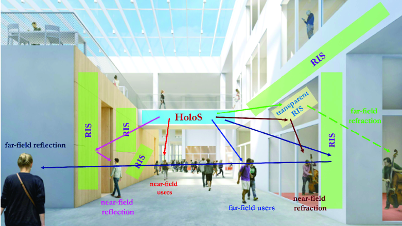
The main advantage of an RIS consists of controlling the propagation environment besides the end points of a transmission link, i.e., transmitters and receivers, without the need of requiring power amplifiers, radio frequency chains, and digital signal processors. An RIS operates in the analog domain directly on the electromagnetic waves. The main advantage of a HoloS consists of being equipped with a very large number of reconfigurable metamaterial elements (like an RIS) but with a limited number of radio frequency chains. This feature is highly desirable, since it reduces the number of radio frequency chains while offering higher beamforming and spatial multiplexing gains 9324910. Notably, these surfaces, if sufficiently large in size, may provide spatial multiplexing gains, i.e., multiple orthogonal communication modes, even in free-space line-of-sight propagation environments 9139337, 9475156, 8289332. In wireless communication systems and networks, RIS and HoloS are jointly deployed in the environment to boost the communication performance. An illustration of this emerging communication scenario is shown in Fig. 1.
Specifically, thanks to their expected large electrical size, RIS and HoloS may bring fundamentally new challenges to the design and optimization of wireless networks. One of them is the need of engineering and optimizing wireless communication networks whose devices may likely operate in the near-field of each other and, therefore, the electromagnetic waves can no longer be assumed to be characterized by a planar wavefront, but a spherical wavefront needs to be accounted for at the design stage arxiv.2112.05989. Also, the possibility of packing on an intelligent surface hundreds or thousands of radiating elements at sub-wavelength inter-distances requires new communication models that account, at the optimization stage, for the mutual coupling among the elements MDR_MutualImpedances, MDR_MutualImpedancesOpt, MDR_MutualImpedancesMIMO, 9762020.
2 Electromagnetically Consistent Modeling of Reconfigurable Intelligent Surfaces
In this chapter, we focus our attention on RISs. The deployment and optimization of RISs in wireless networks need several challenges to be tackled. Interested readers can consult, e.g., Cunhua_Magazine, MDR_JSAC for a comprehensive discussion. One of the major and open research challenges in RIS-aided wireless communications lies in developing and utilizing electromagnetically-consistent models that account for the practical implementation of RISs. A comprehensive summary of the communication models most widely utilized in wireless communications for RISs is reported in arxiv.2110.00833. From the overview in arxiv.2110.00833, it is apparent that three main communication models are typically utilized:
-
1.
The locally periodic discrete model;
-
2.
The mutually coupled antenna-elements model;
-
3.
The inhomogeneous sheets of surface impedance model.
Interested readers are referred to arxiv.2110.00833 for a comprehensive discussion of the main characteristics, strengths, and limitations of these models. In this contribution, we focus our attention on the locally periodic discrete model, since it is the most widely used model in wireless communications and in the field of digital metasurfaces adom.201700455. According to this model, an RIS is modeled as an ensemble of reconfigurable elements that can be configured in a finite number of states. From an implementation standpoint, each RIS reconfigurable element is made of one or several engineered scattering elements and some electronic circuits. From a signal and system (or communication) standpoint, each RIS reconfigurable element is associated with a discrete-valued alphabet, sometimes referred to as lookup table or codebook, which determines the finite number of wave manipulations that each RIS reconfigurable element can apply to the incident electromagnetic waves.
According to arxiv.2110.00833, each value of the alphabet (or state of the RIS) can be interpreted as the (electric field) reflection coefficient of an infinite and homogeneous surface whose constituent elements are all configured to the same state. This definition and characterization of the alphabet of each RIS reconfigurable element introduces some limitations on the applicability of the locally periodic discrete model: The model may not be accurate if the desired wave transformation is not “slowly-varying” at the scale of the wavelength of the electromagnetic waves. In other words, the model can be applied if a “not-too-small” number of neighboring RIS reconfigurable elements is configured to the same state, so as to ensure that, locally, each RIS reconfigurable element “sees” other RIS reconfigurable elements configured to the same value of the alphabet. This “slowly-varying” or “locally periodic” condition needs to be carefully evaluated when utilizing this communication model for RISs.
3 Realistic Scattering Models for Reconfigurable Intelligent Surfaces
The numerical results in arxiv.2110.00833 show, in addition, that the presence of imperfections (non-ideal effects), with respect to the theoretically optimum, of the RIS configuration that is required to realize the desired wave transformations may result in the existence of higher-order harmonics (or grating lobes in antenna theory) towards undesired directions. Also, any periodic RIS that is illuminated by a plane wave may reradiate several electromagnetic waves according to Floquet’s theorem, whose intensity depends on how the RIS surface impedance is engineered Sergei_MacroscopicModel, Vittorio_RayTracing. In the context of the locally periodic discrete model, inaccuracies in the design of the alphabet of the RIS scattering elements, i.e., the use of a non-ideal alphabet, with respect to the theoretically optimum, may result in the presence of reradiated but undesired electromagnetic waves. Specifically, three major practical issues can be identified when engineering the RIS reconfigurable elements (which encompass the scattering elements and the electronic circuits):
-
1.
The phases of the complex-valued elements of the alphabet of the RIS reconfigurable elements are not exactly the same as those identified at the design stage. Assume, for example, that one wants to realize a three-bit digitally controllable RIS. In theory, the phase difference between the complex-valued elements of the alphabet should be an integer multiple of 45 degrees. However, it may not be possible to realize eight different phases with this constraint 9632392. Also, it may not be possible to realize any phase shifts, i.e., the range of admissible phase shifts may be smaller than 360 degrees.
-
2.
The amplitudes of the complex-valued elements of the alphabet of the RIS reconfigurable elements are not exactly unitary and they are not independent of the corresponding phases of the complex-valued elements of the alphabet. For example, if one wants to apply a given phase shift to an incident electromagnetic wave, the corresponding amplitude may be much smaller than one. This results in a phase-dependent signal attenuation 9115725, Romain_RIS-Prototype.
-
3.
Due to the implementation and power constraints associated with any electronic circuit, it may be possible to realize alphabets for the RIS reconfigurable elements with only a finite number of complex-valued elements, i.e., the number of RIS states is finite. An often convenient implementation, due to the ease of realization, reduced cost, and limited power consumption, is the design of binary surfaces whose elements can only take two possible states and whose nominal phase shifts differ by 180 degrees. Recent results have shown that these extremely quantized surfaces may result in far-field reradiatiated beams towards undesired directions, e.g., towards the direction that is symmetrical with respect to the desired direction of radiation for the case study of anomalous reflectors 9424172.
4 Modeling Reconfigurable Intelligent Surfaces in Wireless Communications
In wireless communications, in spite of these considerations, the typical assumptions made on the complex-valued elements of the alphabet of the RIS reconfigurable elements (usually referred to as the RIS reflection coefficients in wireless communications) when considering the locally periodic discrete model for RIS are the following 9326394:
-
1.
The amplitudes of the RIS reflection coefficients are assumed to be unitary or constant as a function of the corresponding phases;
-
2.
The phase shifts of the RIS reflection coefficients are either assumed to be continuous-valued variables or discrete-valued variables with equal phase differences;
-
3.
In some cases, the amplitudes and phases of the RIS reflection coefficients are assumed to be optimized independently of one another.
Most probably, however, the main assumption made in the context of wireless communications lies in optimizing a utility function at particular locations of one or multiple receivers, while disregarding the reradiation pattern of an RIS towards other directions. Inherently, therefore, the presence and impact of undesired reradiated beams are not explicitly investigated. The presence of unwanted reradiations may, however, not be negligible if realistic alphabets (reflection coefficients) for the RIS reconfigurable elements are utilized. The existence of these undesired beams has, in particular, two major and negative consequences on a communication system:
-
1.
Some power is directed towards directions that are different from the nominal ones. This implies that the power efficiency of an RIS towards the target directions is reduced. Since an RIS does not usually amplify the incident signals, this may further limit the transmission coverage;
-
2.
The unwanted beams result in interference that an RIS injects into the network, which may negatively affect the performance of other network users.
5 Chapter Contribution
Motivated by these considerations, we evince that it is necessary to comprehensively study the reradiation pattern of an RIS when practical reflection models (alphabets) are utilized, according to the assumption of the locally periodic discrete model. The aim of the present chapter is to study this open issue, which, to the best of our understanding, is not sufficiently understood by the wireless community. More precisely, we consider some recently reported alphabets for RISs that operate at different frequencies and study the reradiation pattern of each of them. Special focus is put on comparing currently available RIS alphabets based on existing hardware prototypes against “ideal” alphabets whose elements have unit amplitudes and evenly spaced phases, as is often assumed in wireless communications. Our numerical results show that major differences in the reradiation pattern of an RIS usually exist, especially either when binary RIS reconfigurable elements are utilized, or when the amplitudes and phases of the reflection coefficients are not independent of one another and the variations of the amplitudes with the phases are not negligible.
6 Chapter Organization
The rest of this chapter is organized as follows. In Section 2, the considered system model is described. To focus our attention on the main contribution of the chapter, i.e., the impact of practical alphabets of the RIS reconfigurable elements, the canonical system model with a single transmit and a single receive antenna is considered. In Section 3, we describe the algorithm that is utilized for optimizing an RIS under the assumption that each RIS reconfigurabale element is characterized by complex-valued elements (alphabet) whose amplitudes and phases are not necessarily independent of one another. In Section LABEL:sec:NUM_Results, several numerical results are illustrated by utilizing experimentally validated alphabets for RISs. In Section LABEL:sec:Conclusions, finally, we provide concluding remarks.
2 System Model
We consider a single-user system in which a single-antenna transmitter and a single-antenna receiver communicate through an RIS. For simplicity, we assume that no direct link between the transmitter and the receiver exists. We denote by and the channel matrices from the transmitter to the RIS and from the RIS to the receiver, respectively.
As far as the RIS is concerned, we model it as a uniform planar array with RIS reconfigurable elements that are arranged and are equally spaced on rows and columns. The RIS is assumed to be centered at the origin and to lie in the plane (i.e., ). The inter-distance between the RIS reconfigurable elements on each row and column is denoted by and , respectively. The inter-distances and are referred to as the geometric periods of the RIS in the context of dynamic metasurfaces. The surface area of each RIS reconfigurable element is , and it encompasses one or multiple scattering elements and the associated tuning circuits. For simplicity, we can assume that each RIS reconfigurable element is made of a single radiating element and one or more positive-intrinsic-negative (PIN) diodes Linglong_Testbed or varactors Romain_RIS-Prototype. Each RIS reconfigurable element can be optimized independently of the others.
As mentioned in Section 1, we adopt the locally periodic discrete model for an RIS arxiv.2110.00833. Accordingly, each RIS reconfigurable element is associated with a set of complex-valued coefficients (the RIS alphabet) denoted by , , …, . Each element of the alphabet is obtained by appropriately configuring the electronic circuits of the RIS reconfigurable element. For ease of description, we assume that the RIS operates as a reflecting surface. From the physical standpoint, therefore, the complex-valued coefficient has the meaning of a reflection coefficient, i.e., the ratio between the reflected electric field and the incident electric field, of an infinite RIS whose elements are all configured to the same state. Therefore, the corresponding equivalent structure is a homogeneous surface that realizes specular reflection. According to this definition, each RIS reconfigurable element is characterized by means of locally periodic boundary conditions, and, since an RIS is not endowed with power amplifiers, the reflection coefficients for have an amplitude that is, by definition, less than one, i.e., for . However, this neither necessarily implies that the amplitude of is a constant independent of the phase of nor that the amplitude and the phase of can be optimized independently of one another.
Examples of alphabets that can be found in the literature and that correspond to available hardware platforms, i.e., are experimentally validated, can be found in Table 1 and Table 2, which were originally reported in arxiv.2110.00833. As far as the RIS prototype introduced in Hongliang_OmniSurface is concerned, we have reported only the reflection coefficients in Table 1 and have ignored the transmission coefficients, since they are of no interest for our study. The reflection coefficients in Table 1 and Table 2 are utilized in Section LABEL:sec:NUM_Results to obtain the numerical results. It is worth mentioning that the “typical” model utilized in wireless communications for a reflecting-type RIS assumes that (i) either for any possible phase of and that the phase of can be adjusted to any continuous values or (ii) for any possible phase of and that the phase of can be adjusted to a finite number of phase shifts that are evenly spaced within the range degrees. Further details are provided in Section LABEL:sec:NUM_Results.
| Reference | Size of the unit cell | Reflection Coefficient |
|---|---|---|
| Wankai_PathLoss-mmWave ( GHz) | ||
| Wankai_PathLoss-mmWave ( GHz) | ||
| Hongliang_OmniSurface ( GHz) | ||
| Linglong_Testbed ( GHz) |
| Voltage | ||
|---|---|---|
| 0 | -1.517 dB | 32.798∘ |
| 0.25 | -1.807 dB | 40.854∘ |
| 0.5 | -3.156 dB | 46.807∘ |
| 0.75 | -5.59 dB | 53.543∘ |
| 1 | -9.576 dB | 70.32∘ |
| 1.25 | -20.563 dB | -167.158∘ |
| 1.5 | -6.615 dB | -73.171∘ |
| 1.75 | -3.029 dB | -49.627∘ |
| 2 | -1.959 dB | -35.908∘ |
| 2.5 | -0.874 dB | -23.263∘ |
| 3 | -0.749 dB | -16.087∘ |
| 3.5 | -0.469 dB | -12.663∘ |
| 4 | -0.528 dB | -9.925∘ |
| 5 | -0.439 dB | -6.906∘ |
Under the considered modeling assumptions, the achievable rate per unit bandwidth can be formulated as follows:
| (1) |
where is the transmitted power, it the noise power at the receiver, is the th entry of the channel matrix , is the th entry of the channel matrix , and is the value of the reflection coefficient of the th RIS reconfigurable element, with for and .
Since we are interested in characterizing the reradiation pattern of an RIS as a function of the alphabet of the RIS reconfigurable elements, we focus our attention on free-space propagation. Accordingly, it was recently proved in Wankai_PathLoss-mmWave, Wankai_PathLoss that the power received at the generic location can be formulated as follows:
| (2) |
where the following notation is used:
-
•
is the imaginary unit, , and where is the wavelength;
-
•
is the location of the transmitter;
-
•
is the center point of the th RIS reconfigurable element;
-
•
is the received power at ;
-
•
and are the antenna gains of the transmitter and receiver, respectively, where is the angle between the transmitter and the center point of the th RIS reconfigurable element and is the angle between the transmitter and the center point of the th RIS reconfigurable element;
-
•
is the distance between the transmitter and the center point of the th RIS reconfigurable element;
-
•
is the distance between the center point of the th RIS reconfigurable element and the receiver.
In the next section, based on this signal model, we propose a simple algorithm for optimizing the link rate in \eqrefRate. It is worth mentioning that the proposed optimization algorithm can be applied to any channel model, and that the free-space model is considered only for illustration and because we are interested in characterizing the reradiation pattern of an RIS.
3 Optimization Algorithm
Let be the matrix of complex values and let denote the alphabet of each RIS reconfigurable element, i.e., is the feasible set of for and . The maximization of the rate in \eqrefRate in a free-space channel model is equivalent to the following constrained optimization problem:
| (3a) | |||
| (3b) | |||
where the following two identities hold:
| (4) |
| (5) |
The formulated optimization problem in \eqrefLocal_Optimization_Problem is characterized by the optimization variables that can only take discrete values, which prevents us from using gradient-based optimization methods. Moreover, the discrete values in the set do not possess any specific structure that can be exploited for optimization purposes: They are generic complex numbers. Finally, the fact that only discrete-valued phase shifts can be applied by an RIS that is characterized by the feasible set makes it impossible to perfectly compensate the phases of the channels and for any and . In principle, given the discrete nature of the feasible set, it is always possible to resort to an exhaustive search over the set . However, this would require searching over configurations of the matrix , which is computationally infeasible for practical values of and . In fact, typical values for are of the order of hundreds or thousands, while is of the order of units. This motivates us to develop optimization algorithms with a complexity that is linear in , i.e., with the total number of RIS reconfigurable elements.
The approach that we propose to solve the formulated optimization problem in \eqrefLocal_Optimization_Problem is based on the alternating optimization principle, i.e., the reflection coefficients are optimized sequentially one at a time. To elaborate, the optimization of the generic reflection coefficient , while all other reflection coefficients are kept fixed, is stated as follows: